Description
File Details
- Manual Type: Structural Repair Manual
- Brand: Canadair
- Model: Regional Jet
- Chapter: 55 – Stabilizers
- Language: English
- Page Count: 410
- File Format: PDF
- Date: March 2006
Chapters Covered
- 55-00-00 – General & Allowable Damage
- Structural Classification
- Stations (Horizontal Stab, Elevator, Vertical Stab, Rudder)
- Structural Identification
- Extruded & Machined Parts
- Formed Parts
Complete PDF Bookmark Tree
Complete Bookmarks
The complete bookmarks in the “Canadair Regional Jet Structural Repair Manual – Chapter 55 Stabilizers – March 2006 PDF” are as follows:
+Chapter 55p. 1
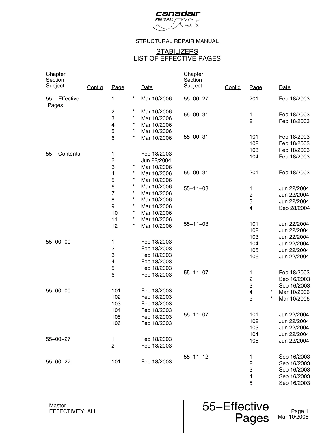
Effective Pagesp. 1
Contentsp. 7
+Section 00p. 19
+55-00-00p. 19
+55-00-00-00p. 19
+Horizontal Stabilizer Stationsp. 20
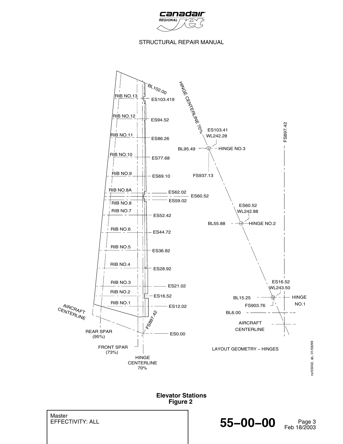
+Elevator Stationsp. 21
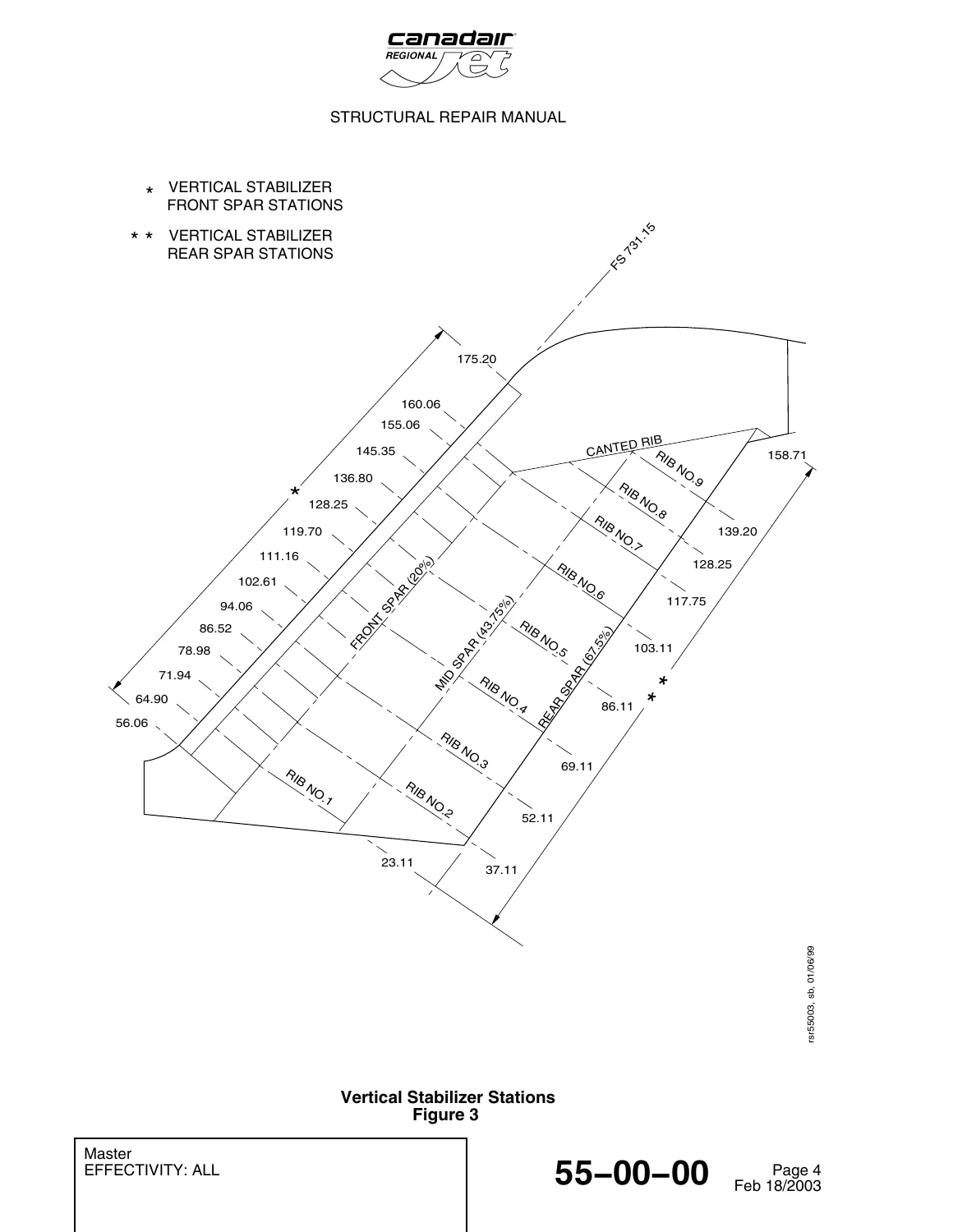
+Vertical Stabilizer Stationsp. 22
+Rudder Stationsp. 23
+Stabilizers – Structural Identificationp. 24
+55-00-00-01p. 25
+Extruded and Machined Parts (Other than Fittings) – Allowable Damage – Generalp. 26
Figure 101 (Sheet 1)p. 26
Figure 101 (Sheet 2)p. 27
+Formed Parts – Allowable Damage – Generalp. 29
Figure 102 (Sheet 1)p. 29
+55-00-27p. 31
+55-00-27-00p. 31
+Structural Identification of Stabilizer Fittingsp. 32
55-00-27-01p. 33
55-00-27-02p. 35
+55-00-31p. 37
+55-00-31-00p. 37
+Stabilizers Skin and Platingp. 38
+55-00-31-01p. 39
+Stabilizer Skin and Plating – Allowable Damage – Generalp. 40
Figure 101 (Sheet 1)p. 40
Figure 101 (Sheet 2)p. 41
55-00-31-02p. 43
+Section 11p. 45
+55-11-03p. 45
+55-11-03-00p. 45
+Horizontal Stabilizer Stringers – Structural Identificationp. 46
Figure 1 (Sheet 1)p. 46
Figure 1 (Sheet 2)p. 47
+55-11-03-01p. 49
+Horizontal Stabilizer Stringers – Allowable Damagep. 50
Figure 101 (Sheet 1)p. 50
Figure 101 (Sheet 2)p. 51
Figure 101 (Sheet 3)p. 52
+55-11-07p. 55
+55-11-07-00p. 55
+Horizontal Stabilizer Spars – Structural Identificationp. 56
Figure 1 (Sheet 1)p. 56
Figure 1 (Sheet 2)p. 57
+55-11-07-01p. 61
+Horizontal Stabilizer Spars – Allowable Damagep. 62
Figure 101 (Sheet 1)p. 62
Figure 101 (Sheet 2)p. 63
Figure 101 (Sheet 3)p. 64
+55-11-12p. 67
+55-11-12-00p. 67
+Horizontal Stabilizer Ribs – Structural Identificationp. 68
Figure 1 (Sheet 1)p. 68
Figure 1 (Sheet 2)p. 69
Figure 1 (Sheet 3)p. 70
Figure 1 (Sheet 4)p. 71
+55-11-12-01p. 77
+Horizontal Stabilizer Ribs – Allowable Damagep. 78
Figure 101 (Sheet 1)p. 78
Figure 101 (Sheet 2)p. 79
+Horizontal Stabilizer Ribs – Allowable Damagep. 80
Figure 102 (Sheet 1)p. 80
Figure 102 (Sheet 2)p. 81
Figure 102 (Sheet 3)p. 82
+55-11-27p. 85
+55-11-27-00p. 85
+Attach/Attached Fittings, Horizontal Stabilizer – Structural Identificationp. 86
Figure 1 (Sheet 1)p. 86
Figure 1 (Sheet 2)p. 87
55-11-27-01p. 91
55-11-27-02p. 93
+55-11-31p. 95
+55-11-31-00p. 95
+Horizontal Stabilizer Skin and Plating – Structural Identificationp. 96
Figure 1 (Sheet 1)p. 96
Figure 1 (Sheet 2)p. 97
+55-11-31-01p. 103
+Horizontal Stabilizer Skin and Plating – Allowable Damagep. 104
Figure 101 (Sheet 1)p. 104
Figure 101 (Sheet 2)p. 105
Figure 101 (Sheet 3)p. 106
Figure 101 (Sheet 4)p. 107
+55-11-31-02p. 109
+Horizontal Stabilizer Skin Repairp. 112
Figure 202 (Sheet 1)p. 112
Figure 202 (Sheet 2)p. 113
Figure 202 (Sheet 3)p. 114
+55-11-32p. 115
+55-11-32-00p. 115
+Horizontal-Stabilizer Access Panels – Structural Identificationp. 116
+55-11-32-01p. 119
+Horizontal Stabilizer Access Doors – Allowable Damagep. 120
Figure 101 (Sheet 1)p. 120
Figure 101 (Sheet 2)p. 121
Figure 101 (Sheet 3)p. 122
Figure 101 (Sheet 4)p. 123
Figure 101 (Sheet 5)p. 124
+Section 12p. 125
+55-12-00p. 125
+55-12-00-00p. 125
+Horizontal–Stabilizer Secondary Structure ― Structural Identification Figure 1p. 126
55-12-00-01p. 127
55-12-00-02p. 129
+55-12-01p. 131
+55-12-01-00p. 131
+Horizontal-Stabilizer Leading Edge – Structural Identificationp. 132
+55-12-01-01p. 135
+Horizontal Stabilizer – Leading Edge – Allowable Damage Limitsp. 137
Figure 102 (Sheet 1)p. 137
Figure 102 (Sheet 2)p. 138
Figure 102 (Sheet 3)p. 139
+55-12-01-02p. 141
+Permanent Flush Repair of the Horizontal-Stabilizer Leading-Edgep. 144
Figure 202 (Sheet 1)p. 144
Figure 202 (Sheet 2)p. 145
Figure 202 (Sheet 3)p. 146
+55-12-51p. 147
+55-12-51-00p. 147
+Fillets and Fairings, Horizontal Stabilizer – Structural Identificationp. 148
55-12-51-01p. 151
55-12-51-02p. 157
+Section 20p. 159
+55-20-00p. 159
+55-20-00-00p. 159
+Elevators – Structural Identificationp. 160
Figure 1 (Sheet 1)p. 160
Figure 1 (Sheet 2)p. 161
+55-20-00-01p. 173
+Elevators – Allowable Damagep. 174
Figure 101 (Sheet 1)p. 174
Figure 101 (Sheet 2)p. 175
+55-20-00-02p. 177
+Elevator Skin Repairp. 180
+Elevator Skin Flush Repairp. 181
+Elevator Skin Non-Flush Repairp. 182
Figure 204 (Sheet 1)p. 182
Figure 204 (Sheet 2)p. 183
Figure 204 (Sheet 3)p. 184
Figure 204 (Sheet 4)p. 185
Figure 204 (Sheet 5)p. 186
Figure 204 (Sheet 6)p. 187
+Section 30p. 189
+Section 31p. 191
+55-31-00p. 191
+55-31-00-00p. 191
+Vertical-Stabilizer Main Structure – Structural Identificationp. 192
55-31-00-01p. 193
55-31-00-02p. 195
+55-31-03p. 197
+55-31-03-00p. 197
+Vertical Stabilizer Stringers – Structural Identificationp. 198
+55-31-03-01p. 201
+Vertical Stabilizer Stringers – Allowable Damagep. 202
Figure 101 (Sheet 1)p. 202
Figure 101 (Sheet 2)p. 203
Figure 101 (Sheet 3)p. 204
55-31-03-02p. 207
+55-31-07p. 209
+55-31-07-00p. 209
+Vertical Stabilizer Spars – Structural Identificationp. 210
+55-31-07-01p. 213
+Vertical Stabilizer Spars – Allowable Damagep. 214
Figure 101 (Sheet 1)p. 214
Figure 101 (Sheet 2)p. 215
55-31-07-02p. 217
+55-31-12p. 219
+55-31-12-00p. 219
+Vertical Stabilizer Ribs – Structural Identificationp. 220
Figure 1 (Sheet 1)p. 220
Figure 1 (Sheet 2)p. 221
+55-31-12-01p. 225
+Vertical Stabilizer Ribs – Allowable Damagep. 226
Figure 101 (Sheet 1)p. 226
Figure 101 (Sheet 2)p. 227
Figure 101 (Sheet 3)p. 228
Figure 101 (Sheet 4)p. 229
Figure 101 (Sheet 5)p. 230
55-31-12-02p. 233
+55-31-27p. 235
+55-31-27-00p. 235
+Vertical Stabilizer Attach/Attached Fittings – Structural Identificationp. 236
Figure 1 (Sheet 1)p. 236
Figure 1 (Sheet 2)p. 237
55-31-27-01p. 241
55-31-27-02p. 243
+55-31-31p. 245
+55-31-31-00p. 245
+Vertical Stabilizer Skin and Plating – Structural Identificationp. 246
Figure 1 (Sheet 1)p. 246
Figure 1 (Sheet 2)p. 247
Figure 1 (Sheet 3)p. 248
+55-31-31-01p. 251
+Vertical Stabilizer Skin and Plating – Allowable Damagep. 252
Figure 101 (Sheet 1)p. 252
Figure 101 (Sheet 2)p. 253
Figure 101 (Sheet 3)p. 254
Figure 101 (Sheet 4)p. 255
Figure 101 (Sheet 5)p. 256
+55-31-31-02p. 259
+Vertical Stabilizer Skin – Non-Flush Repairp. 262
Figure 202 (Sheet 1)p. 262
Figure 202 (Sheet 2)p. 263
Figure 202 (Sheet 3)p. 264
Figure 202 (Sheet 4)p. 265
Figure 202 (Sheet 5)p. 266
Figure 202 (Sheet 6)p. 267
+55-31-32p. 269
+55-31-32-00p. 269
+Vertical-Stabilizer Access Panels – Structural Identificationp. 270
Figure 1 (Sheet 1)p. 270
Figure 1 (Sheet 2)p. 271
Figure 1 (Sheet 3)p. 272
+55-31-32-01p. 275
+Vertical Stabilizer Access Panels – Allowable Damagep. 276
Figure 101 (Sheet 1)p. 276
Figure 101 (Sheet 2)p. 277
Figure 101 (Sheet 3)p. 278
+55-31-55p. 279
+55-31-55-00p. 279
+Rudder-Actuator Support Structure – Structural Identificationp. 280
55-31-55-01p. 283
55-31-55-02p. 285
+Section 32p. 287
+55-32-00p. 287
+55-32-00-00p. 287
+Vertical-Stabilizer Secondary Structure – Structural Identificationp. 288
55-32-00-01p. 289
55-32-00-02p. 291
+55-32-01p. 293
+55-32-01-00p. 293
+Vertical-Stabilizer Leading Edge – Structural Identificationp. 294
Figure 1 (Sheet 1)p. 294
Figure 1 (Sheet 2)p. 295
Figure 1 (Sheet 3)p. 296
Figure 1 (Sheet 4)p. 297
Figure 1 (Sheet 5)p. 298
+55-32-01-01p. 303
+Vertical Stabilizer Leading Edge Skin – Allowable Damagep. 304
Figure 101 (Sheet 1)p. 304
Figure 101 (Sheet 2)p. 305
Figure 101 (Sheet 3)p. 306
+55-32-01-02-01p. 309
+Vertical Stabilizer Leading Edge Generic Repairp. 312
Figure 202 (Sheet 1)p. 312
Figure 202 (Sheet 2)p. 313
Figure 202 (Sheet 3)p. 314
Figure 202 (Sheet 4)p. 315
+55-32-32p. 317
+55-32-32-00p. 317
+Vertical-Stabilizer Access Panels – Structural Identificationp. 318
Figure 1 (Sheet 1)p. 318
Figure 1 (Sheet 2)p. 319
Figure 1 (Sheet 3)p. 320
55-32-32-01p. 323
+55-32-51p. 325
+55-32-51-00p. 325
+Fillets and Fairings – Vertical-to-Horizontal Stabilizers – Structural Identificationp. 326
Figure 1 (Sheet 1)p. 326
Figure 1 (Sheet 2)p. 327
Figure 1 (Sheet 3)p. 328
Figure 1 (Sheet 4)p. 329
Figure 1 (Sheet 5)p. 330
Figure 1 (Sheet 6)p. 331
Figure 1 (Sheet 7)p. 332
Figure 1 (Sheet 8)p. 333
Figure 1 (Sheet 9)p. 334
+55-32-51-01p. 341
+Fillets and Fairings – Vertical-to-Horizontal Stabilizer – Allowable Damagep. 342
Figure 101 (Sheet 1)p. 342
+Fillets and Fairings, Vertical-to-Horizontal Stabilizersp. 345
Figure 102 (Sheet 1)p. 345
Figure 102 (Sheet 2)p. 346
55-32-51-02p. 353
+55-32-52p. 355
+55-32-52-00p. 355
+Ram Air Intake and Dorsal Fairing – Structural Identificationp. 356
Figure 1 (Sheet 1)p. 356
Figure 1 (Sheet 2)p. 357
Figure 1 (Sheet 3)p. 358
55-32-52-01p. 361
+Section 40p. 367
+55-40-00p. 367
+55-40-00-00p. 367
+Rudder – Structural Identificationp. 368
Figure 1 (Sheet 1)p. 368
Figure 1 (Sheet 2)p. 369
Figure 1 (Sheet 3)p. 370
Figure 1 (Sheet 4)p. 371
Figure 1 (Sheet 5)p. 372
Figure 1 (Sheet 6)p. 373
Figure 1 (Sheet 7)p. 374
Figure 1 (Sheet 8)p. 375
Figure 1 (Sheet 9)p. 376
Figure 1 (Sheet 10)p. 377
Figure 1 (Sheet 11)p. 378
Figure 1 (Sheet 12)p. 379
Figure 1 (Sheet 13)p. 380
Figure 1 (Sheet 14)p. 381
+55-40-00-01p. 393
+Rudder – Allowable Damagep. 394
Figure 101 (Sheet 1)p. 394
Figure 101 (Sheet 2)p. 395
Figure 101 (Sheet 3)p. 396
Figure 101 (Sheet 4)p. 397
Figure 101 (Sheet 5)p. 398
+55-40-00-02p. 401
+Rudder – Cut-out Area – Repairp. 404
+Rudder – Trailing Edge Profile – Repairp. 405
+Rudder – Trailing Edge Skin – Repairp. 406
+Rudder – Skin, Bottom-end – Repairp. 407
+Rudder – Skin, Over Bays – Repairp. 408
+Rudder – Skin, One Rivet – Repairp. 409
- 55-10-00 – Horizontal Stabilizer
- 55-11-03: Stringers
- 55-11-07: Spars
- 55-11-12: Ribs
- 55-11-27: Attach/Attached Fittings
- 55-11-31: Skin and Plating
- 55-11-32: Access Panels
- 55-12-00 – Horizontal Stabilizer Secondary Structure
- 55-12-01: Leading Edge
- 55-12-51: Fillets and Fairings
- 55-20-00 – Elevators
- Structural Identification
- Allowable Damage
- Repairs (Flush & Non-Flush Skin Repairs)
- 55-30-00 – Vertical Stabilizer
- 55-31-03: Stringers
- 55-31-07: Spars
- 55-31-12: Ribs
- 55-31-27: Attach/Attached Fittings
- 55-31-31: Skin and Plating
- 55-31-32: Access Panels
- 55-31-55: Rudder Actuator Support
- 55-32-00 – Vertical Stabilizer Secondary Structure
- 55-32-01: Leading Edge
- 55-32-32: Access Panels
- 55-32-51: Fillets and Fairings
- 55-32-52: Ram Air Intake and Dorsal Fairing
- 55-40-00 – Rudder
- Structural Identification
- Allowable Damage
- Non-Flush Skin Repairs
This comprehensive structural repair manual for the Canadair Regional Jet provides detailed engineering data for maintenance and repair of the aircraft’s stabilizers, elevators, and rudder. It contains critical information on structural identification, allowable damage limits, and approved repair procedures for primary and secondary structures.
The manual is essential for aircraft maintenance engineers, structural technicians, and repair station personnel working on Canadair Regional Jet airframes. It includes precise station diagrams, material specifications, and structural classifications for all major components. Detailed repair instructions are provided for skins, stringers, spars, ribs, fittings, leading edges, and access panels, including specific methods for flush and non-flush repairs.
Capabilities & Importance
This Canadair Regional Jet Structural Repair Manual – Chapter 55 Stabilizers – March 2006 PDF enables professionals to:
- Identify all structural components of the horizontal and vertical stabilizers, elevators, and rudder.
- Assess damage against established allowable limits using detailed figures and tables.
- Perform approved structural repairs on skins, stringers, spars, ribs, and fittings following step-by-step procedures.
- Correctly identify, inspect, and repair composite components such as fairings and fillets.
- Maintain critical structural integrity and airworthiness by adhering to Bombardier’s approved repair data and inspection requirements (SDIR).
Having this official structural repair manual is vital for ensuring that all repairs are performed in compliance with airworthiness authority standards, preserving the safety and longevity of the aircraft. The procedures, material specifications, and allowable damage limits contained within this document are essential for any workshop maintaining the Canadair Regional Jet.
Instant Digital Access
This listing provides an instant digital download in PDF format. No physical item will be shipped. You can access the manual immediately after purchase on any device, including computers, tablets, and smartphones. It is fully printable, allowing for hard copies to be used in the workshop.

Reviews
There are no reviews yet.