★ TRUSTED BY 321,897+ PROFESSIONALS WORLDWIDE
🏒
Trusted Business
Verified & Licensed
πŸ›‘οΈ
Virus Free Files
100% Safe Downloads
πŸ”’
Secure Payment
SSL Protected
⚑
Instant Delivery
Available Immediately
Sale!

Airbus A330 PW Engine Indicating Chapter 77 Aircraft Maintenance Manual

Original price was: $34.95.Current price is: $19.95.

Complete Airbus A330 (PW) Engine Indicating Chapter 77 Aircraft Maintenance Manual covering N1/N2 speed, EPR, EGT, T3, ambient pressure, and engine vibration indicating systems. Includes removal/installation, adjustment/test, inspection/check, and cleaning procedures with component locations, system descriptions, and illustrated figures for Pratt & Whitney powered A330 aircraft.

⚑
Instant PDF Download
Available immediately
πŸ’Ύ
Save to Your Device
Download & keep forever
πŸ›‘οΈ
Antivirus Scanned
100% virus-free
🌍
Trusted Worldwide
175,000+ customers

Description

Airbus A330 PW Engine Indicating Chapter 77 Aircraft Maintenance Manual

This Airbus A330 (PW) Engine Indicating Chapter 77 Aircraft Maintenance Manual is the definitive technical reference for maintaining, troubleshooting, and repairing the engine indicating systems on Pratt & Whitney powered Airbus A330 aircraft. Whether you are performing routine removal and installation of speed probes, conducting EPR system leak tests, inspecting EGT thermocouple probes, or diagnosing vibration indicating faults, this AMM chapter provides the exact procedures, torque values, clearances, and safety warnings required to complete the job correctly.

Covering Chapter 77 in full, this manual spans from general system descriptions and component locations through to detailed removal, installation, adjustment, test, inspection, cleaning, and repair procedures for every major engine indicating component on the PW-powered A330.

File Details

  • Manual Type: Aircraft Maintenance Manual (AMM) β€” Chapter 77
  • Brand: Airbus
  • Model: A330 (Pratt & Whitney engines)
  • Chapter: 77 β€” Engine Indicating (PW)
  • Language: English
  • File Format: PDF
  • Revision: Revision nΒ° 53, Oct 01/11

Chapters Covered in This A330 Engine Indicating Manual

  • 77-00-00 β€” (PW) Engine Indicating β€” General: system description, component location, functional designations
  • 77-10-00 β€” (PW) Power: description and operation
  • 77-11-00 β€” (PW) Shaft Speed Indicating: N1 speed (P2.5/T2.5) probe, PMA (N2) stator, ECAM engine/warning display, N1 and N2 indication
  • 77-11-11 β€” Probe β€” Speed (N1): removal, installation, and adjustment of the N1 speed (P2.5/T2.5) probe
  • 77-12-00 β€” (PW) Pressure Indicating: ambient pressure sensor description and operation
  • 77-12-11 β€” Sensor β€” Ambient Pressure: removal and installation of left and right ambient pressure sensors
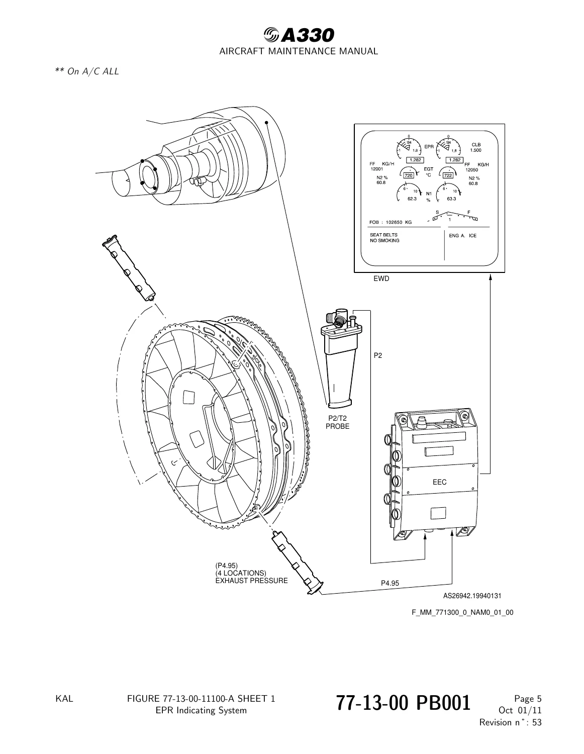
  • 77-13-00 β€” (PW) Engine Pressure Ratio (EPR) Indicating System: EPR indicating system, P2/T2 probe, EPR P4.95 probe, ECAM EPR indication
  • 77-13-11 β€” Probe β€” EPR P4.95 Thermocouple: removal, installation, EPR P4.95 system leak test, visual inspection
  • 77-13-12 β€” Probe β€” P2/T2: removal, installation, P2/T2 probe and P2 supply tube leak check, probe heater test, MCDU menus
  • 77-20-00 β€” (PW) Temperature: description and operation
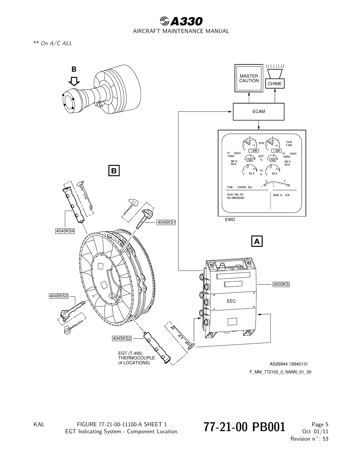
  • 77-21-00 β€” (PW) Exhaust Gas Temperature (EGT) Indicating System: EGT indicating system, T4.95 thermocouple probe, T3 thermocouple probe, EGT/T3 harness, ECAM EGT indication
  • 77-21-11 β€” Probe EGT T4.95 Thermocouple: removal, installation, probe test, visual inspection, cleaning
  • 77-21-12 β€” Harness β€” EGT/T3: removal and installation (PRE and POST SB PW4G-100-77-5 configurations)
  • 77-21-13 β€” Probe β€” T3 Thermocouple: removal and installation (PRE and POST SB PW4G-100-77-5, PRE and POST SB PW4G-100-72-131)
  • 77-30-00 β€” (PW) Analyzers: N1 speed location, remote charge converter (RCC), P. Flange accelerometer, EIVMU, EEC, N1 and N2 vibration display
  • 77-32-00 β€” (PW) Engine Vibration Indicating System: system description, engine vibration accelerometer (exhaust case), accelerometer harness
  • 77-32-11 β€” Accelerometer β€” A β€” Repairs: No. 1 bearing accelerometer repair kit installation and removal
  • 77-32-12 β€” Accelerometer β€” Engine Vibration B (Exhaust): removal and installation
  • 77-32-13 β€” RCC (Remote Charge Converter): removal and installation
  • 77-32-14 β€” Harness β€” Engine Vibration Accelerometer Exhaust: removal and installation

Complete PDF Bookmark Tree

Complete Bookmarks

The complete bookmarks in the β€œAirbus A330 PW Engine Indicating Chapter 77 Aircraft Maintenance Manual” are as follows:

Manual Front Matter
Chapter 05 – TIME LIMITS – MAINTENANCE CHECKS
Chapter 06 – DIMENSIONS AND AREAS
Chapter 07 – LIFTING AND SHORING
Chapter 08 – LEVELING AND WEIGHING
Chapter 09 – TOWING AND TAXIING
Chapter 10 – PARKING, MOORING, STORAGE & RETURN TO SERVICE
Chapter 11 – PLACARDS AND MARKINGS
Chapter 12 – SERVICING
Chapter 20 – STANDARD PRACTICES – AIRFRAME
Chapter 21 – AIR CONDITIONING
Chapter 22 – AUTO FLIGHT
Chapter 23 – COMMUNICATIONS
Chapter 24 – ELECTRICAL POWER
Chapter 25 – EQUIPMENT/FURNISHINGS
Chapter 26 – FIRE PROTECTION
Chapter 27 – FLIGHT CONTROLS
Chapter 28 – FUEL
Chapter 29 – HYDRAULIC POWER
Chapter 30 – ICE AND RAIN PROTECTION
Chapter 31 – INDICATING/RECORDING SYSTEMS
Chapter 32 – LANDING GEAR
Chapter 33 – LIGHTS
Chapter 34 – NAVIGATION
Chapter 35 – OXYGEN
Chapter 36 – PNEUMATIC
Chapter 38 – WATER/WASTE
Chapter 45 – ONBOARD MAINTENANCE SYSTEMS (OMS)
Chapter 46 – INFORMATION SYSTEMS
Chapter 47 – INERT GAS SYSTEM
Chapter 49 – AIRBORNE AUXILIARY POWER
Chapter 51 – STANDARD PRACTICES AND STRUCTURES
Chapter 52 – DOORS
Chapter 53 – FUSELAGE
Chapter 54 – NACELLES/PYLONS
Chapter 55 – STABILIZERS
Chapter 56 – WINDOWS
Chapter 57 – WINGS
Chapter 70 – (PW) – STANDARD PRACTICES – ENGINE
Chapter 71 – (PW) – POWER PLANT
Chapter 72 – (PW) – ENGINE
Chapter 73 – (PW) – ENGINE FUEL AND CONTROL
Chapter 74 – (PW) – IGNITION
Chapter 75 – (PW) – AIR
Chapter 76 – (PW) – ENGINE CONTROLS
Chapter 77 – (PW) – ENGINE INDICATINGp. 1
Table of Contentsp. 1
77-00 – (PW) – ENGINE INDICATING – GENERALp. 6
77-00-00 – (PW) – ENGINE INDICATING – GENERALp. 6
77-00-00 PB 001 CONF 17 – ENGINE INDICATING – GENERAL – DESCRIPTION AND OPERATIONp. 6
Generalp. 6
Component Locationp. 7
System Descriptionp. 8
Figure 77-00-00-12150-A – N1 Speed (P2.5/T2.5) Probe-Component Locationp. 9
Figure 77-00-00-12350-A – Permanent Magnet Alternator (PMA) (N2) Stator-Component Locationp. 10
Figure 77-00-00-12400-A – P2/T2 Probe-Compoonent Locationp. 11
Figure 77-00-00-12450-A – Ambient Pressure Sensor-Component Locationp. 12
Figure 77-00-00-12500-A – Engine Pressure Ratio (EPR) P4.95 Probe-Component Locationp. 14
Figure 77-00-00-12550-A – EGT T4.95 Thermocouple Probe and EGT/T3 Harness-Component Locationp. 16
Figure 77-00-00-12600-A – T3 Thermocouple Probe-Component Locationp. 21
Figure 77-00-00-12650-A – No. 1 Bearing Accelerometer Repair Kit Installation-Component Locationp. 22
Figure 77-00-00-12700-A – Engine Vibration Accelerometer (Exhaust Case)-Component Locationp. 23
Figure 77-00-00-12750-A – Engine Vibration Accelerometer Harness (Exhaust Case)-Component Locationp. 24
77-10 – (PW) – POWERp. 25
77-10-00 – (PW) – POWERp. 25
77-10-00 PB 001 CONF 17 – POWER – DESCRIPTION AND OPERATIONp. 25
Generalp. 25
77-11 – (PW) – SHAFT SPEED INDICATINGp. 26
77-11-00 – (PW) – SHAFT SPEED INDICATINGp. 26
77-11-00 PB 001 CONF 17 – SHAFT SPEED INDICATING – DESCRIPTION AND OPERATIONp. 26
Generalp. 26
Component Locationp. 27
System Descriptionp. 28
Operation/Control and Indicatingp. 29
Figure 77-11-00-11100-A – Shaft Speed Indicatingp. 30
Figure 77-11-00-11150-A – N1 Speed (P2.5/T2.5) Probep. 31
Figure 77-11-00-11200-A – Interface/Indicatingp. 32
Figure 77-11-00-11250-A – ECAM Engine/Warning Displayp. 33
Figure 77-11-00-11300-A – N1 Indicationp. 34
Figure 77-11-00-11350-A – N2 Indicationp. 35
77-11-11 – (PW) – PROBE – SPEED (N1)p. 36
77-11-11 PB 401 CONF 17 – PROBE – SPEED (N1) – REMOVAL/INSTALLATIONp. 36
77-11-11-000-802-A – Removal of the N1 Speed (P2.5/T2.5) Probep. 36
Figure 77-11-11-991-00300-A – N1 Speed (P2.5/T2.5) Probep. 39
Figure 77-11-11-991-00400-A – N1 Speed (P2.5/T2.5) Probep. 40
77-11-11-400-802-A – Installation of the N1 Speed (P2.5/T2.5) Probep. 41
77-12 – (PW) – PRESSURE INDICATINGp. 47
77-12-00 – (PW) – PRESSURE INDICATINGp. 47
77-12-00 PB 001 CONF 17 – PRESSURE INDICATING – DESCRIPTION AND OPERATIONp. 47
Generalp. 47
Component Locationp. 48
System Descriptionp. 49
Figure 77-12-00-11100-A – Ambient Pressure Sensorp. 50
Figure 77-12-00-11150-A – Ambient Pressure Sensorp. 51
77-12-11 – (PW) – SENSOR – AMBIENT PRESSUREp. 52
77-12-11 PB 401 CONF 17 – SENSOR – AMBIENT PRESSURE – REMOVAL/INSTALLATIONp. 52
77-12-11-000-801-A – Removal of the Ambient Pressure Sensorp. 52
Figure 77-12-11-991-00100-A – Ambient Pressure Sensor (Right)p. 55
Figure 77-12-11-991-00200-A – Ambient Pressure Sensor (Left)p. 56
77-12-11-400-801-A – Installation of the Ambient Pressure Sensorp. 57
77-13 – (PW) – ENGINE PRESSURE RATIO (EPR) INDICATING SYSTEMp. 61
77-13-00 – (PW) – ENGINE PRESSURE RATIO (EPR) INDICATING SYSTEMp. 61
77-13-00 PB 001 CONF 17 – ENGINE PRESSURE RATIO (EPR) INDICATING SYSTEM – DESCRIPTION AND OPERATIONp. 61
Generalp. 61
Component Locationp. 62
System Descriptionp. 63
Operation/Control and Indicatingp. 64
Figure 77-13-00-11100-A – EPR Indicating Systemp. 65
Figure 77-13-00-11150-A – P2/T2 Probep. 66
Figure 77-13-00-11200-A – Engine Pressure Ratio (EPR) P4.95 Probep. 67
Figure 77-13-00-11250-A – ECAM Engine/Warning Displayp. 69
Figure 77-13-00-11300-A – EPR Indicationp. 70
77-13-11 – (PW) – PROBE – EPR P 4.95 THERMOCOUPLEp. 71
77-13-11 PB 401 CONF 17 – PROBE – EPR P 4.95 THERMOCOUPLE – REMOVAL/INSTALLATIONp. 71
77-13-11-000-801-A – Removal of the Engine Pressure Ratio (EPR) P4.95 Probe.p. 71
Figure 77-13-11-991-00100-A – Engine Pressure Ratio (EPR) P4.95 Probep. 74
Figure 77-13-11-991-00200-A – Engine Pressure Ratio (EPR) P4.95 Probep. 75
77-13-11-400-801-A – Installation of the Engine Pressure Ratio (EPR) P4.95 Probe.p. 76
77-13-11 PB 501 CONF 17 – PROBE – EPR P 4.95 THERMOCOUPLE – ADJUSTMENT/TESTp. 80
77-13-11-790-801-A – EPR P4.95 System Leak Testp. 80
Figure 77-13-11-991-00400-A – EPR P4.95 Sensing Systemp. 85
77-13-11 PB 601 CONF 17 – PROBE – EPR P 4.95 THERMOCOUPLE – INSPECTION/CHECKp. 87
77-13-11-210-801-A – Visual Inspection of the Engine Pressure Ratio (EPR) P4.95 Probe.p. 87
Figure 77-13-11-991-00300-A – Engine Pressure Ratio (EPR) P4.95 Probe Inspection.p. 92
77-13-12 – (PW) – PROBE – P2/T2p. 94
77-13-12 PB 401 CONF 17 – PROBE – P2/T2 – REMOVAL/INSTALLATIONp. 94
77-13-12-000-801-A – Removal of the Inlet Total Pressure/Temperature (P2/T2) Probep. 94
Figure 77-13-12-991-00100-A – Inlet Total Pressure/temperature (P2/T2) Probep. 97
77-13-12-400-801-A – Installation of the Inlet Total Pressure/Temperature (P2/T2) Probep. 98
77-13-12 PB 501 CONF 17 – PROBE – P2/T2 – ADJUSTMENT/TESTp. 102
77-13-12-790-801-A – P2/T2 Probe and P2 Supply Tube Leak Checkp. 102
Figure 77-13-12-991-00600-A – View of Supply Tubes and ECC.p. 106
Figure 77-13-12-991-00700-A – P2/T2 Probe and P2 Hose.p. 107
Figure 77-13-12-991-00800-A – P2 Probe and Air Supply System.p. 108
77-13-12-700-801-A – P2/T2 Probe Heater Test.p. 109
Figure 77-13-12-991-00500-A – Probe Heater Test – MCDU Menus.p. 112
77-20 – (PW) – TEMPERATUREp. 114
77-20-00 – (PW) – TEMPERATUREp. 114
77-20-00 PB 001 CONF 17 – TEMPERATURE – DESCRIPTION AND OPERATIONp. 114
Generalp. 114
77-21 – (PW) – EXHAUST GAS TEMPERATURE (EGT) INDICATING SYSTEMp. 115
77-21-00 – (PW) – EXHAUST GAS TEMPERATURE (EGT) INDICATING SYSTEMp. 115
77-21-00 PB 001 CONF 17 – EXHAUST GAS TEMPERATURE (EGT) INDICATING SYSTEM – DESCRIPTION AND OPERATIONp. 115
Generalp. 115
Component Locationp. 116
System Descriptionp. 117
Operation/Control and Indicatingp. 118
Figure 77-21-00-11100-A – EGT Indicating System – Component Location.p. 119
Figure 77-21-00-11150-A – EGT T4.95 Thermocouple Probe and EGT/T3 Harnessp. 120
Figure 77-21-00-11200-A – T3 Thermocouple Probep. 125
Figure 77-21-00-11250-A – EGT T4.95 Thermocouple Probep. 126
Figure 77-21-00-11300-A – ECAM Engine/Warning Displayp. 127
Figure 77-21-00-11350-A – EGT Indicationp. 128
77-21-11 – (PW) – PROBE EGT T 4.95 THERMOCOUPLEp. 129
77-21-11 PB 401 CONF 17 – PROBE EGT T 4.95 THERMOCOUPLE – REMOVAL/INSTALLATIONp. 129
77-21-11-000-802-A – Removal of the Exhaust Gas Temperature (EGT) T4.95 Thermocouple Probe.p. 129
Figure 77-21-11-991-00200-A – Exhaust Gas Temperature (EGT) T4.95 Thermocouple Probep. 132
Figure 77-21-11-991-00300-A – Exhaust Gas Temperature (EGT) T4.95 Thermocouple Probep. 133
77-21-11-400-802-A – Installation of the Exhaust Gas Temperature (EGT) T4.95 Thermocouple Probe.p. 134
77-21-11 PB 501 CONF 17 – PROBE EGT T 4.95 THERMOCOUPLE – ADJUSTMENT/TESTp. 138
77-21-11-760-801-A – Exhaust Gas Temperature (EGT) T4.95 Thermocouple Probe Testp. 138
Figure 77-21-11-991-00700-A – Exhaust Gas Temperature (EGT) T4.95 Thermocouple Probe Test.p. 142
77-21-11 PB 601 CONF 17 – PROBE EGT T 4.95 THERMOCOUPLE – INSPECTION/CHECKp. 143
77-21-11-210-801-A – Visual Inspection of the Exhaust Gas Temperature (EGT) T4.95 Thermocouple Probep. 143
77-21-11 PB 701 CONF 17 – PROBE EGT T 4.95 THERMOCOUPLE – CLEANING/PAINTINGp. 146
77-21-11-100-801-A – Cleaning of the Exhaust Gas Temperature (EGT) T4.95 Thermocouple Probep. 146
77-21-12 – (PW) – HARNESS – EGT /T3p. 149
77-21-12 PB 401 CONF 17 – HARNESS – EGT /T3 – REMOVAL/INSTALLATIONp. 149
77-21-12-000-801-A – Removal of the Exhaust Gas Temperature (EGT)/T3 Harnessp. 149
Figure 77-21-12-991-00100-A – Exhaust Gas Temperature (EGT)/T3 Harness.p. 154
Figure 77-21-12-991-00200-A – Exhaust Gas Temperature (EGT)/T3 Harness.p. 155
Figure 77-21-12-991-00300-A – POST SB PW4G-100-77-5 Exhaust Gas Temperature (EGT)/T3 Harnessp. 157
Figure 77-21-12-991-00400-A – PRE SB PW4G-100-77-5 Exhaust Gas Temperature (EGT)/T3 Harnessp. 158
Figure 77-21-12-991-00500-A – POST SB PW4G-100-77-5 Exhaust Gas Temperature (EGT)/T3 Harnessp. 159
Figure 77-21-12-991-00600-A – Exhaust Gas Temperature (EGT)/T3 Harnessp. 160
77-21-12-400-801-A – Installation of the Exhaust Gas Temperature (EGT)/T3 Harnessp. 161
77-21-13 – (PW) – PROBE – T3 THERMOCOUPLEp. 167
77-21-13 PB 401 CONF 17 – PROBE – T3 THERMOCOUPLE – REMOVAL/INSTALLATIONp. 167
77-21-13-000-801-A – Removal of the T3 Thermocouple Probep. 167
Figure 77-21-13-991-00200-A – T3 Thermocouple Probe (PRE SB PW4G-100-77-5) (PRE SB PW4G-100-72-131)p. 171
Figure 77-21-13-991-00300-A – T3 Thermocouple Probe (PRE SB PW4G-100-77-5) (PRE SB PW4G-100-72-131)p. 172
Figure 77-21-13-991-00400-A – T3 Thermocouple Probe (POST SB PW4G-100-77-5) (POST SB PW4G-100-72-131)p. 173
Figure 77-21-13-991-00500-A – T3 Thermocouple Probe (POST SB PW4G-100-77-5) (POST SB PW4G-100-72-131)p. 174
77-21-13-400-801-A – Installation of the T3 Thermocouple Probep. 175
77-30 – (PW) – ANALYZERSp. 180
77-30-00 – (PW) – ANALYZERSp. 180
77-30-00 PB 001 CONF 17 – ANALYZERS – DESCRIPTION AND OPERATIONp. 180
Generalp. 180
Component Locationp. 181
System Descriptionp. 182
Power Supplyp. 183
Interfacep. 184
Operation/Control and Indicatingp. 185
Figure 77-30-00-12200-A – N1 Speed – Locationp. 188
Figure 77-30-00-12250-A – Remote Charge Converter (RCC) – Locationp. 189
Figure 77-30-00-12300-A – P.Flange accelerometer B – Locationp. 190
Figure 77-30-00-12350-A – Accelerometer – Locationp. 191
Figure 77-30-00-12400-A – EIVMU – Locationp. 192
Figure 77-30-00-12450-A – EEC – Locationp. 193
Figure 77-30-00-13550-A – Interfacep. 194
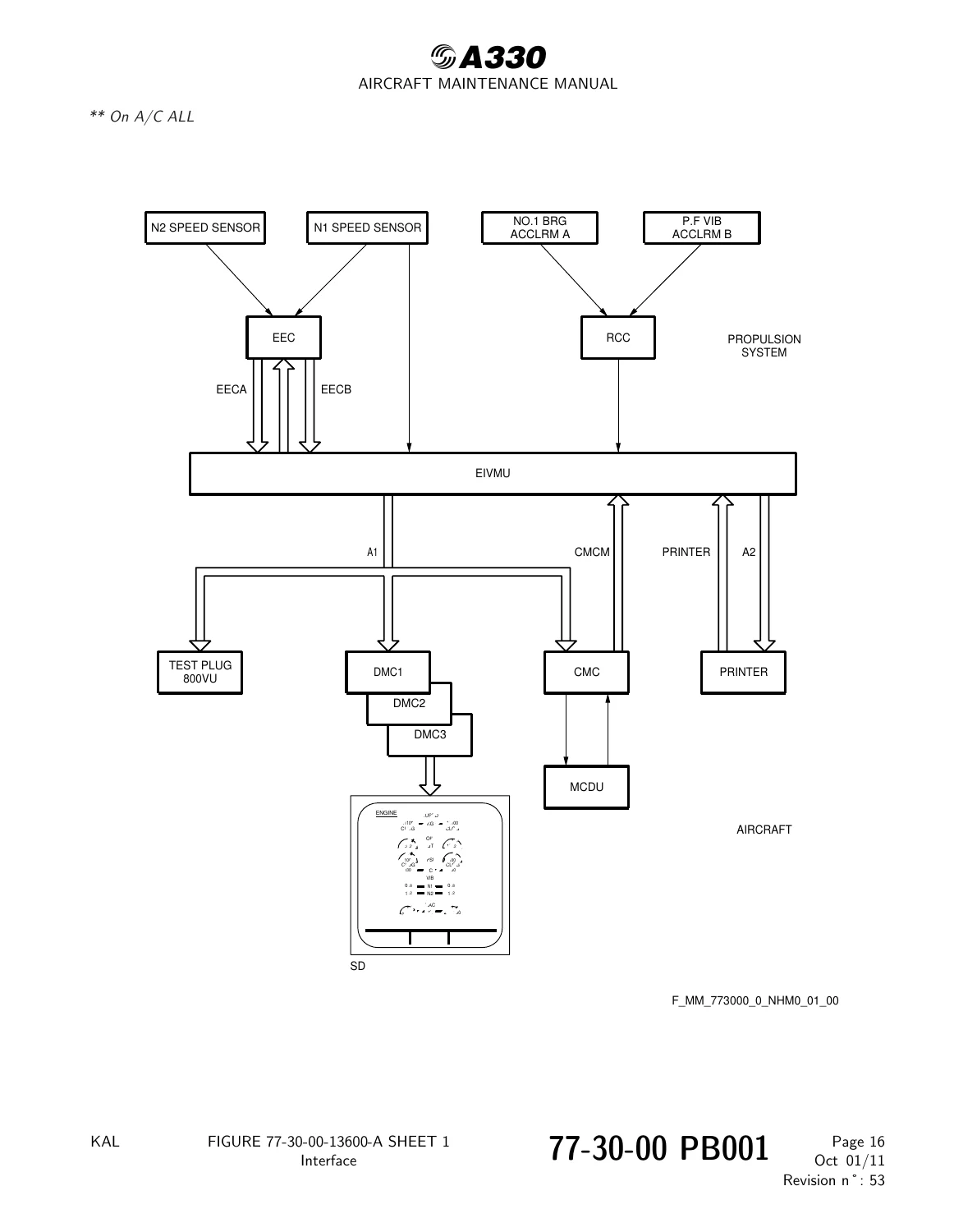
Figure 77-30-00-13600-A – Interfacep. 195
Figure 77-30-00-17250-A – N1 Vibration Displayp. 196
Figure 77-30-00-17300-A – N2 Vibration Displayp. 197
77-32 – (PW) – ENGINE VIBRATION INDICATING SYSTEMp. 198
77-32-00 – (PW) – ENGINE VIBRATION INDICATING SYSTEMp. 198
77-32-00 PB 001 CONF 17 – ENGINE VIBRATION INDICATING SYSTEM – DESCRIPTION AND OPERATIONp. 198
Generalp. 198
Component Locationp. 199
System Descriptionp. 200
Figure 77-32-00-11100-A – Engine Vibration Indicating Systemp. 201
Figure 77-32-00-11150-A – Engine Vibration Accelerometer Harness (Exhaust Case)p. 202
Figure 77-32-00-11200-A – Engine Vibration Accelerometer (Exhaust Case)p. 203
Figure 77-32-00-11250-A – No. 1 Bearing Accelerometer Repair Kit Installationp. 204
77-32-11 – (PW) – ACCELEROMETER – Ap. 205
77-32-11 PB 801 CONF 17 – ACCELEROMETER – A – REPAIRSp. 205
77-32-11-300-801-A – No. 1 Bearing Accelerometer Repair (Repair Kit Installation)p. 205
Figure 77-32-11-991-00400-A – No. 1 Bearing Accelerometer Repair Kit Installationp. 211
77-32-11-300-802-A – No. 1 Bearing Accelerometer Repair (Repair Kit Removal)p. 213
Figure 77-32-11-991-00600-A – No. 1 Bearing Accelerometer Repair Kit Removalp. 218
77-32-12 – (PW) – ACCELEROMETER – ENGINE VIBRATION B (EXHAUST)p. 220
77-32-12 PB 401 CONF 17 – ACCELEROMETER – ENGINE VIBRATION B (EXHAUST) – REMOVAL/INSTALLATIONp. 220
77-32-12-000-802-A – Removal of the Engine Vibration Accelerometer (Exhaust)p. 220
Figure 77-32-12-991-00200-A – Engine Vibration Accelerometer (Exhaust Case).p. 223
Figure 77-32-12-991-00300-A – Engine Vibration Accelerometer (Exhaust Case).p. 224
77-32-12-400-802-A – Installation of the Engine Vibration Accelerometer (Exhaust)p. 225
77-32-13 – (PW) – RCC (REMOTE CHARGE CONVERTER)p. 230
77-32-13 PB 401 CONF 17 – RCC (REMOTE CHARGE CONVERTER) – REMOVAL/INSTALLATIONp. 230
77-32-13-000-801-A – Removal of the Remote Charge Converter (RCC)p. 230
Figure 77-32-13-991-00100-A – Remote Charge Converter (RCC)p. 233
77-32-13-400-801-A – Installation of the Remote Charge Converter (RCC)p. 235
77-32-14 – (PW) – HARNESS – ENGINE VIBRATION ACCELEROMETER EXHAUSTp. 240
77-32-14 PB 401 CONF 17 – HARNESS – ENGINE VIBRATION ACCELEROMETER EXHAUST – REMOVAL/INSTALLATIONp. 240
77-32-14-000-801-A – Removal of the Engine Vibration Accelerometer Harness (Exhaust Case)p. 240
Figure 77-32-14-991-00100-A – Engine Vibration Accelerometer Harness (Exhaust Case).p. 243
77-32-14-400-801-A – Installation of the Engine Vibration Accelerometer Harness (Exhaust Case)p. 244
Chapter 78 – (PW) – EXHAUST
Chapter 79 – (PW) – OIL
Chapter 80 – (PW) – STARTING

What This Chapter 77 AMM Covers

The Airbus A330 PW Engine Indicating Chapter 77 Aircraft Maintenance Manual covers the complete engine indicating system used to sense, transmit, and display engine operating parameters and component/systems data. It details how the Electronic Engine Control (EEC) receives signals from engine probes and sensors and correlates the data for engine control and cockpit display.

The shaft speed indicating section explains how the N1 speed (P2.5/T2.5) probe generates an oscillation signal proportional to the LPC/LPT coupling rotational speed, with 60 teeth producing a frequency of 216,000 Hz at 100 percent N1. The manual includes the N1 probe gap adjustment procedure using beeswax or paraffin wax to verify the correct shim class, with measurement limits between 0.020 in. and 0.050 in. The N2 speed signal is produced from a winding of the Permanent Magnet Alternator (PMA), and the manual provides the PMA stator component location for both engines.

For pressure indicating, the manual describes the two ambient pressure sensor ports that transmit pressures to a common sensing tube where they are averaged and sent to the Pamb transducer in the EEC. It includes removal and installation procedures for both left and right ambient pressure sensors, with torque values for the clamp bolt, adapter, and castellated nut.

The Engine Pressure Ratio (EPR) indicating system section covers the P2/T2 probe and four P4.95 probes that measure exhaust gas pressure. EPR is the primary parameter used to set thrust, calculated as the ratio of exhaust gas total pressure to front compressor inlet total pressure (P4.95/P2). The manual includes the EPR P4.95 system leak test procedure using regulated dry air or nitrogen at 30 psig, with a maximum allowable pressure decrease of 0.5 psig over 30 to 60 seconds. It also covers the P2/T2 probe heater test using MCDU menus, and P2 supply tube leak checks.

The Exhaust Gas Temperature (EGT) indicating system section covers the four T4.95 thermocouple probes and T3 thermocouple probe. Each EGT probe has six chromel/alumel thermocouple elements in three radial positions, with three elements averaged for Channel A and three for Channel B. The manual provides detailed removal and installation procedures for the EGT probes, T3 probe, and EGT/T3 harness, including torque values for the thermocouple nuts (18–22 LBF.IN for larger ID nuts, 15–18 LBF.IN for smaller ID nuts). The EGT probe test section covers insulation resistance checks (minimum 10K ohms) and continuity checks using a microammeter and hot air blower.

The engine vibration indicating system section covers the No. 1 bearing accelerometer, exhaust case (Flange P) accelerometer, Remote Charge Converter (RCC), and Engine Interface and Vibration Monitoring Unit (EIVMU). It includes the No. 1 bearing accelerometer repair kit installation and removal procedures, with detailed torque values for the kit brackets and sensor mounting bolts. The manual also covers removal and installation of the engine vibration accelerometer (exhaust case), RCC, and accelerometer harness.

Component Locations and Access

The manual includes component location tables with FIN numbers, functional designations, panels, zones, access doors, and ATA references. Key components covered include:

  • 4013KS β€” N1 Speed (P2.5/T2.5) Probe
  • 4044KS β€” PMA Stator / EEC
  • 5000EV1–5000EV4 β€” EPR P4.95 Probes
  • 4014KS β€” P2/T2 Probe
  • 4045KS1–4045KS4 β€” EGT T4.95 Thermocouple Probes
  • 4047KS β€” T3 Thermocouple Probe
  • 4028KS β€” EGT/T3 Harness
  • 4002EV β€” No. 1 Bearing Accelerometer (ACCLRM A)
  • 4003EV β€” Exhaust Case Accelerometer (ACCLRM B)
  • 4006EV β€” Remote Charge Converter (RCC)
  • 4580KS β€” Engine Vibration Accelerometer Harness (Exhaust Case)
  • 1KS1 / 1KS2 β€” EIVMU (Engine Interface and Vibration Monitoring Unit)
  • 4000KS β€” EEC (Electronic Engine Control)

Procedures Included

This Airbus A330 Chapter 77 AMM contains complete maintenance procedures with step-by-step instructions, cautions, warnings, torque values, and referenced figures. Procedures include removal and installation of the N1 speed probe, ambient pressure sensors, EPR P4.95 probes, P2/T2 probe, EGT T4.95 thermocouple probes, T3 thermocouple probe, EGT/T3 harness, No. 1 bearing accelerometer repair kit, engine vibration accelerometer, RCC, and vibration accelerometer harness.

Adjustment and test procedures include the N1 speed probe gap adjustment, EPR P4.95 system leak test, P2/T2 probe and P2 supply tube leak check, P2/T2 probe heater test, and EGT T4.95 thermocouple probe test. Inspection and check procedures include visual inspection of the EPR P4.95 probe and EGT T4.95 thermocouple probe. Cleaning procedures are provided for the EGT T4.95 thermocouple probe.

Safety and Compliance

The manual includes critical safety warnings for thrust reverser deactivation before working on or around the translating cowl, engine shutdown waiting periods (5 minutes for most procedures, 60 minutes before EPR leak test), and cautions regarding electrical connector assembly using the correct tools and procedures to prevent in-flight shutdown risk. Circuit breaker open, safety, and tag procedures are provided for the FADEC A and B engine circuit breakers on panels 722VU and 742VU.

Who This Manual Is For

This Airbus A330 PW Engine Indicating Chapter 77 Aircraft Maintenance Manual is essential for aircraft maintenance engineers, avionics technicians, line maintenance crews, and base maintenance personnel working on Pratt & Whitney powered Airbus A330 aircraft. It is also valuable for aviation training organizations, MRO facilities, and individuals preparing for type ratings or engine indicating system endorsements. The manual is written to Airbus AMM standards with precise technical values and referenced figures throughout.

Get Your Airbus A330 PW Engine Indicating Manual Today

With this Airbus A330 PW Engine Indicating Chapter 77 Aircraft Maintenance Manual, you can confidently perform removal and installation of speed probes, pressure sensors, thermocouple probes, accelerometers, the remote charge converter, and associated harnesses. You can carry out system leak tests, probe heater tests, gap adjustments, and insulation resistance checks using the exact procedures and torque values specified by Airbus for Pratt & Whitney powered A330 aircraft. Correct procedures and specifications matter because incorrect installation of engine indicating components can lead to inaccurate cockpit indications, engine control faults, or in-flight shutdown risk.

IMAGES PREVIEW

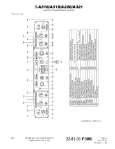
Airbus A330 PW Engine Indicating Chapter 77 Aircraft Maintenance Manual β€” PDF page 65 preview
Airbus A330 PW Engine Indicating Chapter 77 Aircraft Maintenance Manual β€” PDF page 119 preview
Airbus A330 PW Engine Indicating Chapter 77 Aircraft Maintenance Manual β€” PDF page 195 preview

Delivered as an instant PDF download after payment, this manual requires no shipping and no waiting. Access it immediately on any device β€” laptop, tablet, or smartphone β€” and print the pages you need for the hangar floor. Whether you are troubleshooting an EPR indication fault, replacing an EGT thermocouple, or installing a No. 1 bearing accelerometer repair kit, this AMM chapter gives you the authoritative reference you need.
Reviews

There are no reviews yet.

Be the first to review “Airbus A330 PW Engine Indicating Chapter 77 Aircraft Maintenance Manual”

What Our Customers Say

β˜…β˜…β˜…β˜…β˜… Live reviews from customers
Loading customer reviews...
0
    0
    Your Cart
    Your cart is emptyReturn to Shop
    πŸ›’
    Recently Purchased
    πŸ•’ verified order