★ TRUSTED BY 321,897+ PROFESSIONALS WORLDWIDE
🏢
Trusted Business
Verified & Licensed
🛡️
Virus Free Files
100% Safe Downloads
🔒
Secure Payment
SSL Protected
Instant Delivery
Available Immediately
Sale!

Airbus A318 A319 A320 A321 Chapter 22 Auto Flight Aircraft Maintenance Manual – Revision 40 2012

Original price was: $49.95.Current price is: $29.95.

Detailed 1278-page Chapter 22 Auto Flight maintenance manual covering the Airbus A318, A319, A320 and A321. Includes autopilot and flight director operation, autothrust, flight augmentation, flight management, FCU and MCDU systems, FMGC architecture, component removal and installation, operational tests, fault isolation, AFS testing and LAND CAT III capability procedures.

Instant PDF Download
Available immediately
💾
Save to Your Device
Download & keep forever
🛡️
Antivirus Scanned
100% virus-free
🌍
Trusted Worldwide
175,000+ customers

Description

Airbus A318 A319 A320 A321 Chapter 22 Auto Flight Aircraft Maintenance Manual

The Airbus A318 A319 A320 A321 Chapter 22 Auto Flight Aircraft Maintenance Manual – Revision 40 2012 is a detailed technical reference devoted to ATA Chapter 22 Auto Flight systems on the A318, A319, A320 and A321. Across 1278 pages, it documents system architecture, control laws, cockpit controls and indications, computer interfaces, component arrangements, operational logic, servicing, removal and installation tasks, adjustment and operational tests, and fault-isolation functions associated with the aircraft automatic flight systems.

The material extends well beyond a basic description of autopilot operation. It follows the interaction between the Automatic Flight System, Flight Management and Guidance Computers, Flight Augmentation Computers, Flight Control Unit, Multipurpose Control and Display Units, aircraft displays, engine interfaces and related control functions. Numerous figures, block diagrams, architecture drawings, control-law diagrams and component illustrations support the technical explanations and maintenance procedures.

File Details

  • Manual type: Aircraft Maintenance Manual – Chapter 22 Auto Flight
  • Aircraft: Airbus A318, A319, A320 and A321
  • Chapter: 22 – Auto Flight
  • Revision: 40
  • Date: May 01/12
  • Language: English
  • Pages: 1278
  • File format: PDF

Automatic Flight System Architecture and Guidance

A substantial part of this Airbus A318 A319 A320 A321 Auto Flight maintenance manual explains how the Automatic Flight System is arranged and interconnected. The general Auto Flight section includes AFS component layouts, computer locations, overall architecture, cockpit controls and indications, engine interconnections, FAC information displayed on the Primary Flight Display, flight-director symbols, flight-mode annunciation, navaid selection and flight-management information displays.

The Autopilot/Flight Director material develops this further with descriptions of AP/FD components and cockpit controls, flight-director orders, level-change operation and interfaces with the flight-control system. Separate illustrations and explanations address rudder, pitch, aileron, spoiler and nose-wheel control, while the manual also traces AP/FD information transmitted to the PFDs and the relationship between the FMGCs and display systems.

Chapters Covered

  • 22-00-00 Auto Flight – General
    • AFS component layout, computer locations, architecture, controls and indications, engine interfaces and PFD information
  • 22-10-00 Autopilot/Flight Director
    • AP/FD architecture, flight-control interfaces, cockpit indication and operational tests
  • 22-11-00 AP/FD Engagement
    • Engagement and disengagement logic, command monitoring, pitch, roll and yaw loops, locking logic and AP OFF warning
  • 22-12-00 Cruise Modes
    • Speed control, HDG/TRK and NAV modes, localizer operation, altitude acquisition and hold, V/S and FPA modes, OPEN CLB, OPEN DES, EXPED and managed level changes
  • 22-13-00 Common Modes
    • Takeoff, SRS, runway modes, ILS approach, LAND, LOC, GLIDE, ROLL OUT, FLARE, FINAL DES and GO AROUND
  • 22-30-00 Autothrust
    • Controls, computer locations, system block diagram, thrust setting, throttle definition, throttle-control-unit checks and operational testing
  • 22-31-00 Autothrust Engagement
    • Engage and disengage logic, engine isolation and A/THR warnings
  • 22-32-00 Autothrust Modes
    • Mode activation, Alpha Floor protection, SPD/MACH law, A/THR basic loop and indications
  • 22-60-00 Flight Augmentation
    • FAC component locations, layout and operational tests
  • 22-61-00 Artificial Feel and Rudder Travel Limiting Computation
    • Rudder travel-limitation architecture, control law, changeover, monitoring and operational test
  • 22-62-00 Rudder Trim Computation
    • Rudder trim function, architecture, actuator control, monitoring and operational test
  • 22-62-11 / 22-62-12 / 22-62-21 Rudder Trim Components
    • Control switch, RUD TRIM/RESET pushbutton and rudder trim indicator removal and installation
  • 22-63-00 Yaw Damper Computation
    • Yaw-damper architecture, servo-actuator interfaces, control law, monitoring and operational test
  • 22-64-00 Configuration and Operational Speed Computation
    • FAC speed computations, FM weight/CG use, flight-path angle, Alpha Floor, windshear detection and low-energy warning
  • 22-65-00 Engagement and Internal Monitoring
    • FAC engagement, computer and transmission monitoring, ADC and IRS processing, sensor monitoring and power-supply monitoring
  • 22-66-00 Flight Augmentation Computer
    • FAC architecture, deactivation/reactivation and FAC removal and installation
  • 22-67-00 FAC Electrical and Hydraulic Power Supply
    • 28VDC and 26VAC supplies, internal power and yaw-damper servo-actuator hydraulic supply
  • 22-68-00 FAC Discrete/Analog Interfaces
    • FAC discrete and analog interface arrangements
  • 22-69-00 FAC ARINC Bus Interfaces
    • ARINC interface architecture
  • 22-70-00 Flight Management System
    • FMS architecture, navigation, lateral and vertical guidance, weight functions, FM data loading and MCDU operational tests

    IMAGES PREVIEW

    Airbus A318 A319 A320 A321 Chapter 22 Auto Flight Aircraft Maintenance Manual - Revision 40 2012 — PDF page 1106 preview
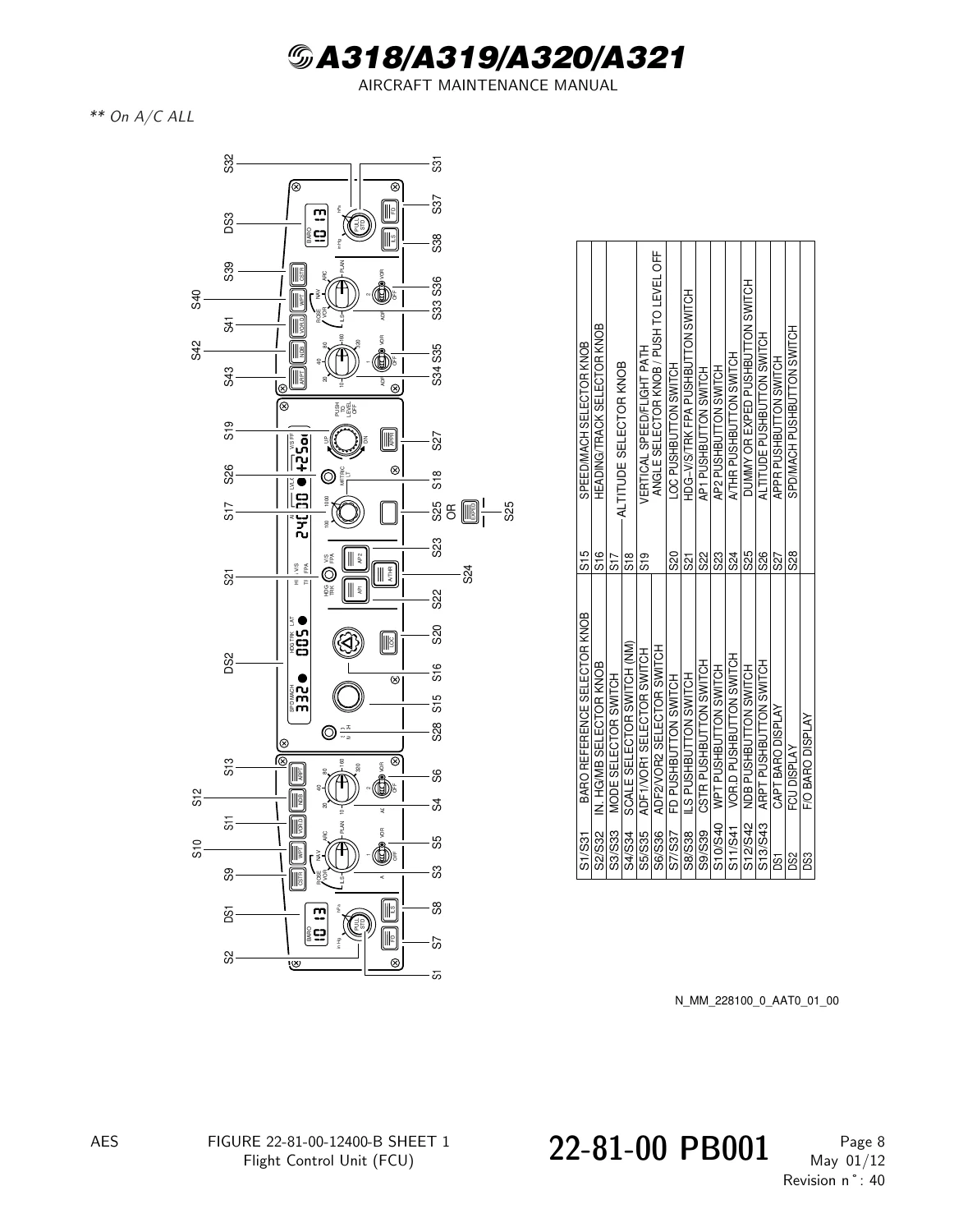
    Airbus A318 A319 A320 A321 Chapter 22 Auto Flight Aircraft Maintenance Manual - Revision 40 2012 — PDF page 42 preview
    Airbus A318 A319 A320 A321 Chapter 22 Auto Flight Aircraft Maintenance Manual - Revision 40 2012 — PDF page 450 preview

  • 22-71-00 Flight Plan/Data Base
    • Flight-plan construction, departures, arrivals, approaches, secondary flight plans, MCDU pages, routes, waypoints, runways and holding patterns
  • 22-72-00 Navigation/Lateral Functions
    • Position computation and updating, radio navigation, leg transitions, path errors, NAV engagement and flight-plan sequencing
  • 22-73-00 Performance/Vertical Functions
    • Flight phases, predictions, takeoff, climb, descent, approach, speed control, weight, fuel and performance functions
  • 22-74-00 Operational Use
    • MCDU front panel, display operation, page hierarchy and message handling
  • 22-75-00 EIS Displays
    • FMGC/EIS interface, ND modes, flight-plan display, offset paths and pseudo waypoints
  • 22-76-00 Data Link and Printer Functions
    • ACARS flight-plan initialization, takeoff-data functions, wind uplinks, reporting and print functions
  • 22-81-00 Flight Control Unit
    • FCU controls, component location, internal arrangement, architecture, monitoring and changeover
  • 22-81-12 Flight Control Unit Maintenance
    • FCU removal and installation
  • 22-82-00 Multipurpose Control and Display Unit
    • MCDU interfaces, component location, front panel, functional layout, block diagram and switching logic
  • 22-82-12 MCDU Maintenance
    • MCDU removal, installation and cleaning
  • 22-83-00 Flight Management and Guidance Computer
    • FMGC front panel, internal arrangement, component location, architecture, power supply and connectors
  • 22-83-34 FMGC Maintenance
    • FMGC removal and installation
  • 22-84-00 FMGS Electrical Power Supply
    • Power supply of FMGCs, FCU, MCDUs and data-loader functions
  • 22-85-00 FMGS Discrete/Analog Interfaces
    • Discrete and analog interfaces associated with the Flight Management and Guidance System
  • 22-86-00 FMGS Bus Interfaces
    • FMGS bus-interface information
  • 22-91-00 Fault Isolation Function – Principle
    • Fault detection and analysis, BITE functions, AFS menus, reports, LRU identification and ground scanning
  • 22-92-00 AFS Fault Isolation
    • Automatic Flight System fault-isolation information
  • 22-96-00 AFS Test
    • AFS test operation, test reports, troubleshooting data and operational test procedure
  • 22-97-00 LAND CAT III Capability Test
    • LAND test logic and operational testing of LAND CAT III capability

Taken as a whole, the manual gives maintenance personnel a system-level view of how automatic guidance, autothrust, flight augmentation and flight management functions are generated, monitored, displayed and tested. The descriptive sections explain the operating logic and interfaces, while the maintenance portions bring that information into practical use through component access, removal and installation, servicing, functional checks, AFS diagnostic routines and system operational testing.

Flight Management, Navigation and Performance Functions

The Flight Management System coverage is especially extensive. It documents general FMS architecture together with navigation, radio-navigation, lateral-guidance, weight and prediction/vertical-guidance architecture. The manual describes how lateral and vertical flight plans underpin navigation, guidance and performance calculations, and it follows the relationship between the FMGCs, MCDUs, PFDs, NDs, FCU and other aircraft systems.

Flight-plan and database material covers departure, arrival, approach and go-around segments; flight-plan initialization; secondary and temporary flight plans; lateral and vertical revision pages; wind entry; stored and new navaids, waypoints, runways and routes; holding patterns; and numerous MCDU page functions. Navigation material includes radio positions, FMGC position computation, localizer and position updating, navigation mode selection, IR alignment, coordinate entry, leg-transition types and lateral-path-error calculations.

Complete PDF Bookmark Tree

Complete Bookmarks

The complete bookmarks in the “Airbus A318 A319 A320 A321 Chapter 22 Auto Flight Aircraft Maintenance Manual – Revision 40 2012” are as follows:

Manual Front Matter
Chapter 05 – TIME LIMITS – MAINTENANCE CHECKS
Chapter 06 – DIMENSIONS AND AREAS
Chapter 07 – LIFTING AND SHORING
Chapter 08 – LEVELING AND WEIGHING
Chapter 09 – TOWING AND TAXIING
Chapter 10 – PARKING, MOORING, STORAGE & RETURN TO SERVICE
Chapter 11 – PLACARDS AND MARKINGS
Chapter 12 – SERVICING
Chapter 20 – STANDARD PRACTICES – AIRFRAME
Chapter 21 – AIR CONDITIONING
Chapter 22 – AUTO FLIGHTp. 1
Table of Contentsp. 1
22-00 – AUTO FLIGHT – GENERALp. 21
22-00-00 – AUTO FLIGHT – GENERALp. 21
22-00-00 PB 001 CONF 00 – AUTO FLIGHT – GENERAL – DESCRIPTION AND OPERATIONp. 21
Generalp. 21
Component Locationp. 22
System Descriptionp. 23
Power Supplyp. 24
Interfacep. 25
Component Descriptionp. 26
Operationp. 27
Figure 22-00-00-13200-B – Layout of the AFS Componentsp. 38
Figure 22-00-00-13300-A – Location of the AFS Computersp. 39
Figure 22-00-00-15200-A – General Architecture of the AFSp. 40
Figure 22-00-00-15300-A – AFS – Controls and Indicatingp. 41
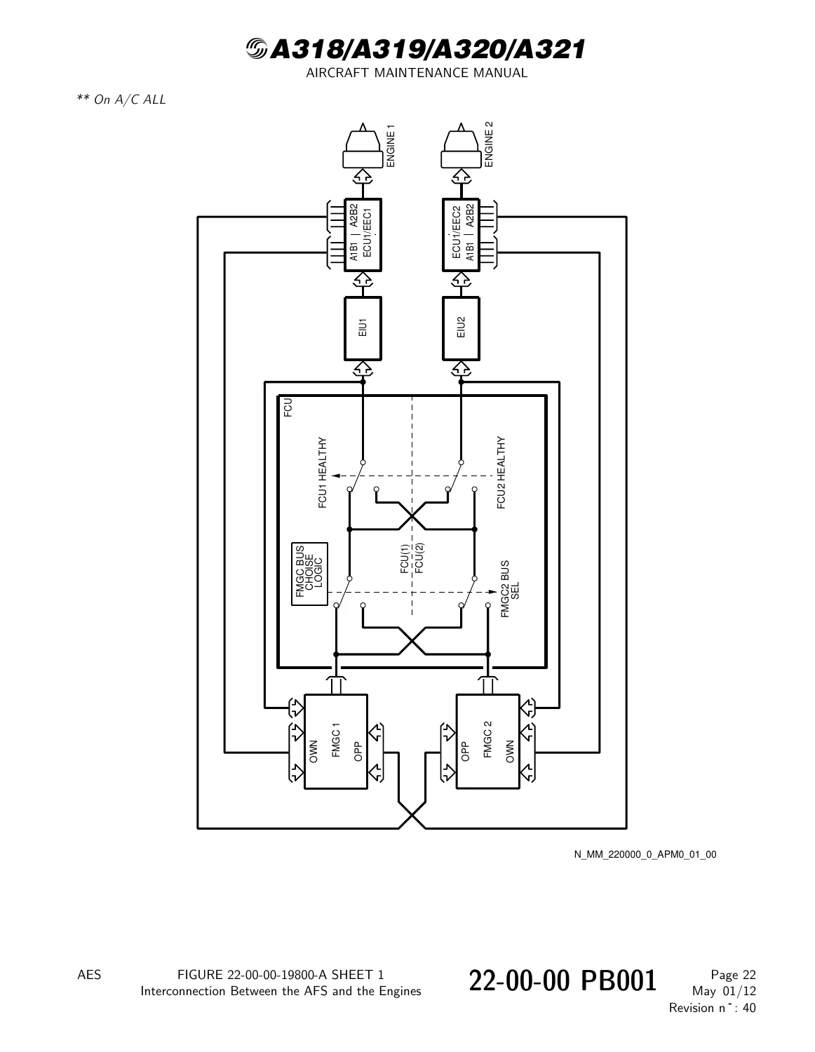
Figure 22-00-00-19800-A – Interconnection Between the AFS and the Enginesp. 42
Figure 22-00-00-22400-A – Display of the FAC Data on the Speed Scale of the PFDp. 43
Figure 22-00-00-22800-A – AFS – FD Symbols on the PFDp. 44
Figure 22-00-00-23100-B – AFS – Annunciator of the Flight Modes on the PFDp. 45
Figure 22-00-00-23300-A – AFS – Selection of Navaidsp. 46
Figure 22-00-00-23400-A – AFS – Display of Flight Management Informationp. 47
22-10 – AUTOPILOT/FLIGHT DIRECTOR (AP/FD)p. 48
22-10-00 – AUTOPILOT/FLIGHT DIRECTOR (AP/FD)p. 48
22-10-00 PB 001 CONF 00 – AUTOPILOT/FLIGHT DIRECTOR (AP/FD) – DESCRIPTION AND OPERATIONp. 48
Generalp. 48
Component Locationp. 49
System Descriptionp. 50
Operationp. 52
Interfacep. 56
Figure 22-10-00-12400-A – Layout of AP/FD and Flight Control Componentsp. 60
Figure 22-10-00-12500-A – Location of Componentsp. 61
Figure 22-10-00-12600-C – Location of FCU and MCDUsp. 63
Figure 22-10-00-14100-A – AP/FD Controls and Indicating in the Cockpitp. 64
Figure 22-10-00-15500-B – Different FD Ordersp. 65
Figure 22-10-00-16300-B – LEVEL CHANGE in Manual and Automatic Controlp. 66
Figure 22-10-00-17700-A – AFS/EFCS Interfacep. 67
Figure 22-10-00-17900-A – Rudder Controlp. 68
Figure 22-10-00-18100-A – Pitch Controlp. 69
Figure 22-10-00-18200-A – Aileron Controlp. 70
Figure 22-10-00-18400-A – Spoiler Controlp. 71
Figure 22-10-00-18600-A – Nose Wheel Controlp. 72
Figure 22-10-00-19000-A – AP/FD Information on the PFDsp. 73
Figure 22-10-00-19400-A – Interface Between FMGCs and PFDsp. 74
22-10-00 PB 501 CONF 00 – AUTOPILOT/FLIGHT DIRECTOR (AP/FD) – ADJUSTMENT/TESTp. 75
22-10-00-710-001-A – Operational Test of the Takeover and Priority Pushbutton Switchesp. 75
22-10-00-710-002-A – Operational Test of Autopilot Disengagement and Locking Devices of the Side Stick Controller and Rudder Pedalsp. 79
22-10-00-710-003-A – Operational Test of the Vertical Speed and Heading Hold Modesp. 83
22-10-00-710-004-A – Operational Test of the FCU Lightingp. 87
22-10-00-710-005-A – Operational Test of the Indicator Lights and Displays of the FCUp. 89
22-10-00-710-006-A – Operational Test of the FCUp. 91
22-10-00-710-007-A – Operational Test of the Altitude Alert Warningp. 95
22-11 – AP/FD ENGAGEMENTp. 100
22-11-00 – AP/FD ENGAGEMENTp. 100
22-11-00 PB 001 CONF 00 – AP/FD ENGAGEMENT – DESCRIPTION AND OPERATIONp. 100
Generalp. 100
System Descriptionp. 101
Figure 22-11-00-12500-A – FD Engagementp. 111
Figure 22-11-00-12700-A – FD – Engage Hardware Logicp. 112
Figure 22-11-00-12800-A – FG HLTY Logicp. 113
Figure 22-11-00-12900-A – FD Disengagementp. 114
Figure 22-11-00-13100-A – AP/FD COND Logicp. 115
Figure 22-11-00-13300-A – AP/FD/A THR Common Conditionsp. 116
Figure 22-11-00-13500-A – FD Basic Loopsp. 117
Figure 22-11-00-13600-A – FD Command Monitoringp. 118
Figure 22-11-00-13800-A – Removal of FD Commandsp. 119
Figure 22-11-00-14400-B – AP – Engage Hardware Logicp. 120
Figure 22-11-00-14600-A – AP COND Logicp. 121
Figure 22-11-00-14700-A – Pitch Basic Loopp. 122
Figure 22-11-00-14800-A – Roll Basic Loopp. 123
Figure 22-11-00-15000-A – Yaw Basic Loopp. 124
Figure 22-11-00-15100-A – AP Command Generationp. 125
Figure 22-11-00-15300-A – Side Stick Controllers and Rudder Pedals – Locking Logicp. 126
Figure 22-11-00-15500-A – AP OFF Warningp. 127
22-12 – CRUISE MODESp. 128
22-12-00 – CRUISE MODESp. 128
22-12-00 PB 001 CONF 00 – CRUISE MODES – DESCRIPTION AND OPERATIONp. 128
Generalp. 128
System Descriptionp. 129
Figure 22-12-00-13700-B – Speed Controlp. 147
Figure 22-12-00-14500-A – Lateral Modes Active in Cruisep. 148
Figure 22-12-00-15100-B – HDG/TRK Selectionp. 149
Figure 22-12-00-15200-B – HDG/TRK Modep. 150
Figure 22-12-00-15300-A – HDG/TRK Control Lawp. 151
Figure 22-12-00-15700-B – Engagement of NAV Mode at Takeoffp. 152
Figure 22-12-00-15800-B – Engagement of NAV Mode (HDG TRK Selector Knob)p. 153
Figure 22-12-00-15900-B – Engagement of NAV Mode (DIRECT TO)p. 154
Figure 22-12-00-16000-A – Horizontal Path Lawp. 155
Figure 22-12-00-16400-B – LOC Modep. 156
Figure 22-12-00-16800-A – AP/FD Longitudinal Modes Activep. 157
Figure 22-12-00-17200-B – ALT ACQ Modep. 158
Figure 22-12-00-17300-B – ALT ACQ Mode – Change of Selected Altitude During the Arming Phasep. 159
Figure 22-12-00-17400-B – ALT ACQ Mode – Change of Selected Altitude During the Capture Phasep. 160
Figure 22-12-00-17500-A – Barometric Correctionp. 161
Figure 22-12-00-17600-A – ALT ACQ Control Lawp. 162
Figure 22-12-00-17800-B – AP Engagement with FD in ALT Modep. 163
Figure 22-12-00-17900-A – ALT HOLD Control Lawp. 164
Figure 22-12-00-18600-B – V/S FPA Mode Selectionp. 165
Figure 22-12-00-18700-B – V/S Mode Engagement Using (Turn and Pull) V/S FPA Selector Knobp. 166
Figure 22-12-00-18800-B – Altitude Hold Through V/S FPA Modep. 167
Figure 22-12-00-18900-A – V/S FPA Control Lawsp. 168
Figure 22-12-00-19200-B – OPEN CLB Mode – Mode Selection When ALT SEL > Current Altitudep. 169
Figure 22-12-00-19300-B – IN OPEN CLB Mode – V/S Mode Selection When ALT SEL < Current Altitudep. 170
Figure 22-12-00-19400-B – OPEN DES Mode – Mode Selection When ALT SEL < Current Alitudep. 171
Figure 22-12-00-19500-B – OPEN CLB Mode – V/S Demand Above Performance Capabilityp. 172
Figure 22-12-00-19600-A – SPD/Mach Control Lawp. 173
Figure 22-12-00-19800-B – EXP Mode – EXP CLB When Aircraft Altitude < Selected Altitudep. 174
Figure 22-12-00-19900-B – EXP Mode – EXP DES When Aircraft Altitude > Selected Altitudep. 175
Figure 22-12-00-20000-B – EXPED Mode – Disengagement by Selected Speed Selectionp. 176
Figure 22-12-00-20700-B – Managed Level Change When A/C Altitude < Selected Altitudep. 177
Figure 22-12-00-20800-B – Managed Level Change – Leveling Off Caused by an Altitude Constraintp. 178
Figure 22-12-00-20900-B – Loss of Managed Level Change Prompted by Loss of Managed Lateral Controlp. 179
Figure 22-12-00-21000-B – DES Mode Disengagement When Climb Phase is Activatedp. 180
Figure 22-12-00-21200-B – CLB Mode in Takeoff Phasep. 181
Figure 22-12-00-21600-A – Vertical Path Control Lawp. 182
22-13 – COMMON MODESp. 183
22-13-00 – COMMON MODESp. 183
22-13-00 PB 001 CONF 00 – COMMON MODES – DESCRIPTION AND OPERATIONp. 183
Generalp. 183
System Descriptionp. 184
Figure 22-13-00-12600-B – Takeoff with NAV Armedp. 195
Figure 22-13-00-12700-A – PITCH TAKEOFF Mode – Logicp. 196
Figure 22-13-00-12800-A – SRS Control Lawp. 197
Figure 22-13-00-13000-A – RUNWAY Mode Logicp. 198
Figure 22-13-00-13100-A – RUNWAY Control Lawp. 199
Figure 22-13-00-13200-B – Takeoff with Heading Presetp. 200
Figure 22-13-00-13700-B – ILS Approachp. 201
Figure 22-13-00-13800-A – LAND Mode Arm – Logicp. 202
Figure 22-13-00-13900-A – Active LOC and GLIDE Modes – Capture Conditionsp. 203
Figure 22-13-00-14000-A – LAND TRACK Logicp. 204
Figure 22-13-00-14100-A – FMA Displaysp. 205
Figure 22-13-00-14200-A – LOC Law – Computation Principlep. 206
Figure 22-13-00-14300-A – LOC CPT Control Lawp. 207
Figure 22-13-00-14400-A – LOC TRACK and ALIGN Control Lawp. 208
Figure 22-13-00-14500-A – ROLL OUT Control Lawp. 209
Figure 22-13-00-14600-A – FLARE Control Lawp. 210
Figure 22-13-00-14700-A – GLIDE Capture and Track Phasep. 211
Figure 22-13-00-14900-B – AREA NAV Approachp. 212
Figure 22-13-00-15000-A – FINAL DES Mode – Logicp. 213
Figure 22-13-00-15400-B – GO AROUND Modep. 214
Figure 22-13-00-15600-A – GO AROUND Logic (Pitch and Roll Axes)p. 215
22-30 – AUTOTHRUSTp. 216
22-30-00 – AUTOTHRUSTp. 216
22-30-00 PB 001 CONF 00 – AUTOTHRUST – DESCRIPTION AND OPERATIONp. 216
Generalp. 216
Component Locationp. 217
System Descriptionp. 218
Figure 22-30-00-12400-A – Cockpit – Location of Controls and Indicationsp. 220
Figure 22-30-00-12500-A – Electronics Rack – Location of Computersp. 221
Figure 22-30-00-13900-A – Autothrust System – Block Diagramp. 222
Figure 22-30-00-14400-A – Thrust Settingp. 223
Figure 22-30-00-14500-A – Throttle Definitionp. 224
22-30-00 PB 401 CONF 00 – AUTOTHRUST – DEACTIVATION/REACTIVATIONp. 225
22-30-00-040-004-A – Check of the Throttle Control Unitsp. 225
22-30-00 PB 501 CONF 00 – AUTOTHRUST – ADJUSTMENT/TESTp. 228
22-30-00-710-003-A – Operational Test of the Engine / Autothrust System Isolation (with AIDS)p. 228
22-31 – AUTOTHRUST ENGAGEMENTp. 233
22-31-00 – AUTOTHRUST ENGAGEMENTp. 233
22-31-00 PB 001 CONF 00 – AUTOTHRUST ENGAGEMENT – DESCRIPTION AND OPERATIONp. 233
Generalp. 233
System Descriptionp. 234
Figure 22-31-00-13000-A – A/THR Engage Logicp. 239
Figure 22-31-00-13800-A – Realization of the Engage or Disengage Logicp. 240
Figure 22-31-00-14200-A – Isolation of the Enginesp. 241
Figure 22-31-00-14700-A – A/THR Warningsp. 242
Figure 22-31-00-14800-A – A/THR Warnings Computation and Displayp. 243
22-32 – AUTOTHRUST MODESp. 244
22-32-00 – AUTOTHRUST MODESp. 244
22-32-00 PB 001 CONF 00 – AUTOTHRUST MODES – DESCRIPTION AND OPERATIONp. 244
Generalp. 244
System Descriptionp. 245
Figure 22-32-00-12500-A – Activation of A/THR Mode according to AP/FD Modesp. 249
Figure 22-32-00-12900-A – Alpha Floor Protectionp. 250
Figure 22-32-00-13400-B – SPD/MACH Lawp. 251
Figure 22-32-00-13500-A – A/THR Basic Loopp. 252
Figure 22-32-00-14300-B – A/THR Indicationsp. 253
22-60 – FLIGHT AUGMENTATION (FAC)p. 254
22-60-00 – FLIGHT AUGMENTATION (FAC)p. 254
22-60-00 PB 001 CONF 00 – FLIGHT AUGMENTATION (FAC) – DESCRIPTION AND OPERATIONp. 254
Generalp. 254
Component Locationp. 256
System Descriptionp. 257
Figure 22-60-00-14000-A – FAC – Component Location (Cockpit)p. 258
Figure 22-60-00-14100-A – FAC – Component Location (Electronics Rack)p. 259
Figure 22-60-00-15400-A – FAC – Component Layoutp. 260
22-60-00 PB 501 CONF 00 – FLIGHT AUGMENTATION (FAC) – ADJUSTMENT/TESTp. 261
22-60-00-710-001-A – Operational Test of the FAC 2 Functionsp. 261
22-60-00-710-002-A – Operational Test of the Automatic Change-Over Functionp. 266
22-60-00-710-003-A – Operational Test of the Return to Low Speed Functionp. 269
22-60-00-710-004-A – Operational Test of the Windshear Functionp. 274
Figure 22-60-00-991-00100-A – Procedure Testp. 277
22-61 – ARTIFICIAL FEEL AND RUDDER TRAVEL LIMITING COMPUTATIONp. 279
22-61-00 – ARTIFICIAL FEEL AND RUDDER TRAVEL LIMITING COMPUTATIONp. 279
22-61-00 PB 001 CONF 00 – ARTIFICIAL FEEL AND RUDDER TRAVEL LIMITING COMPUTATION – DESCRIPTION AND OPERATIONp. 279
Generalp. 279
System Descriptionp. 280
Power Supplyp. 281
Interfacep. 282
Operationp. 283
Test Procedurep. 285
Figure 22-61-00-16800-A – Rudder Travel-Limitation Unit – Block Diagramp. 286
Figure 22-61-00-17400-A – Rudder Travel-Limitation Unit – Control Lawp. 287
Figure 22-61-00-17800-A – Rudder Travel-Limitation – Changeover Logicp. 288
Figure 22-61-00-17900-A – Return to Low Speed Logicp. 289
Figure 22-61-00-18100-A – Monitoring of Rudder Travel-Limiting Functionp. 290
22-61-00 PB 501 CONF 00 – ARTIFICIAL FEEL AND RUDDER TRAVEL LIMITING COMPUTATION – ADJUSTMENT/TESTp. 291
22-61-00-710-001-A – Operational Test of the Rudder Travel Limiting Functionp. 291
22-62 – RUDDER TRIM COMPUTATIONp. 295
22-62-00 – RUDDER TRIM COMPUTATIONp. 295
22-62-00 PB 001 CONF 00 – RUDDER TRIM COMPUTATION – DESCRIPTION AND OPERATIONp. 295
Generalp. 295
System Descriptionp. 296
Operationp. 297
Interface with Controlsp. 300
Test Procedurep. 301
Figure 22-62-00-11200-A – Rudder Trim Functionp. 302
Figure 22-62-00-12600-A – Rudder Trim Architecturep. 303
Figure 22-62-00-14300-A – Rudder Trim Changeover – Logicp. 304
Figure 22-62-00-14700-A – Rudder Trim Actuator – Generation of the Control Orderp. 305
Figure 22-62-00-15500-A – Monitoring of Rudder Trim – Block Diagramp. 306
Figure 22-62-00-17100-A – Rudder-Trim Control Switchp. 307
Figure 22-62-00-17200-A – Interconnections between FAC and Rudder-Trim Control Switchp. 308
Figure 22-62-00-17600-A – Interconnections between FAC and RUD TRIM/RESET Pushbutton Switchp. 309
Figure 22-62-00-17700-A – Rudder Trim Actuator – Principlep. 310
Figure 22-62-00-18100-A – Interconnections between FAC and Rudder Trim Actuatorp. 311
22-62-00 PB 501 CONF 00 – RUDDER TRIM COMPUTATION – ADJUSTMENT/TESTp. 312
22-62-00-710-001-A – Operational Test of the Rudder Trim Functionp. 312
22-62-11 – CONTROL SWITCH – RUDDER TRIMp. 315
22-62-11 PB 401 CONF 00 – CONTROL SWITCH – RUDDER TRIM – REMOVAL/INSTALLATIONp. 315
22-62-11-000-001-A – Removal of the RUD TRIM Control Switchp. 315
Figure 22-62-11-991-00200-A – RUD TRIM Control Switchp. 317
22-62-11-400-001-A – Installation of the RUD TRIM Control Switchp. 318
22-62-12 – PUSHBUTTON SWITCH – RUDDER TRIM/ RESETp. 321
22-62-12 PB 401 CONF 00 – PUSHBUTTON SWITCH – RUDDER TRIM/ RESET – REMOVAL/INSTALLATIONp. 321
22-62-12-000-001-A – Removal of the RUD TRIM/RESET Pushbutton Switchp. 321
Figure 22-62-12-991-00100-A – RUD TRIM/RESET Pushbutton Switchp. 323
22-62-12-400-001-A – Installation of the RUD TRIM/RESET Pushbutton Switchp. 324
22-62-21 – INDICATOR – RUDDER TRIMp. 327
22-62-21 PB 401 CONF 00 – INDICATOR – RUDDER TRIM – REMOVAL/INSTALLATIONp. 327
22-62-21-000-001-A – Removal of the Rudder Trim Indicatorp. 327
Figure 22-62-21-991-00200-A – Rudder Trim Indicatorp. 329
22-62-21-400-001-A – Installation of the Rudder Trim Indicatorp. 330
22-63 – YAW DAMPER COMPUTATIONp. 333
22-63-00 – YAW DAMPER COMPUTATIONp. 333
22-63-00 PB 001 CONF 00 – YAW DAMPER COMPUTATION – DESCRIPTION AND OPERATIONp. 333
Generalp. 333
System Descriptionp. 334
Interfacep. 335
Operationp. 336
Test Procedurep. 338
Figure 22-63-00-11200-A – Yaw Damper Functionp. 339
Figure 22-63-00-12600-A – FAC – Architecture of Yaw Damperp. 340
Figure 22-63-00-14100-A – Interconnections between FAC and Yaw Damper Servo-Actuatorp. 341
Figure 22-63-00-15800-A – Yaw Damper Control-Lawp. 342
Figure 22-63-00-16300-A – Monitoring of Yaw Damper – Block Diagramp. 343
22-63-00 PB 501 CONF 00 – YAW DAMPER COMPUTATION – ADJUSTMENT/TESTp. 344
22-63-00-710-001-A – Operational Test of the Yaw Damper Functionp. 344
22-64 – CONFIGURATION AND OPERATIONAL SPEED COMPUTATIONp. 347
22-64-00 – CONFIGURATION AND OPERATIONAL SPEED COMPUTATIONp. 347
22-64-00 PB 001 CONF 00 – CONFIGURATION AND OPERATIONAL SPEED COMPUTATION – DESCRIPTION AND OPERATIONp. 347
Generalp. 347
System Descriptionp. 348
Operationp. 350
Figure 22-64-00-11200-A – Interconnections Between FAC and Usersp. 354
Figure 22-64-00-12900-A – FAC Data on the Speed Scale of the PFD (Sheet 1/2)p. 355
Figure 22-64-00-13000-A – FAC Data on the Speed Scale of the PFD (Sheet 2/2)p. 356
Figure 22-64-00-14400-A – Speed Computations – General Architecturep. 357
Figure 22-64-00-14700-A – Speed Computation – Use of FM Weight/CGp. 358
Figure 22-64-00-15100-A – FAC – Computation of Aerodynamic Flight-Path Angle (Gamma-a) and Potential Flight-Path Angle (Gamma-T)p. 359
Figure 22-64-00-15500-A – Alpha Floor _ Computation and Interfacep. 360
Figure 22-64-00-15600-A – FAC – Alpha Floorp. 361
Figure 22-64-00-15700-A – ECAM – Rudder Trim Positionp. 362
Figure 22-64-00-16700-A – Windshear Detection Principlep. 363
Figure 22-64-00-16900-A – Windshear Architecturep. 364
Figure 22-64-00-17100-A – MCDU – AFS/Windshear Testp. 365
Figure 22-64-00-17500-A – Low Energy Warning Principlep. 366
Figure 22-64-00-17600-A – Low Energy Warning Architecturep. 367
22-65 – ENGAGEMENT AND INTERNAL MONITORINGp. 368
22-65-00 – ENGAGEMENT AND INTERNAL MONITORINGp. 368
22-65-00 PB 001 CONF 00 – ENGAGEMENT AND INTERNAL MONITORING – DESCRIPTION AND OPERATIONp. 368
Generalp. 368
System Descriptionp. 369
Operationp. 370
Figure 22-65-00-12300-A – FAC Engagement Principlep. 376
Figure 22-65-00-14000-A – Monitoring of the Computerp. 377
Figure 22-65-00-14100-A – Verification of FAC ARINC Transmissionsp. 378
Figure 22-65-00-14800-A – Reconfiguration Tablep. 379
Figure 22-65-00-14900-A – ADC Processingp. 380
Figure 22-65-00-15000-A – Vc Monitoring Principlep. 381
Figure 22-65-00-15100-A – IRS Processingp. 382
Figure 22-65-00-15200-A – Yaw Rate and Lateral Acceleration – Monitoring Principlep. 383
Figure 22-65-00-15300-A – Angle-of-Attack – Monitoring Principlep. 384
Figure 22-65-00-15400-A – SFCC and LGCIU – Principle of Acquisitionp. 385
Figure 22-65-00-15700-A – Monitoring of Internal Power Suppliesp. 386
Figure 22-65-00-16100-A – Sensors – Principlep. 387
Figure 22-65-00-16500-A – 26V/400 Hz Monitoringp. 388
22-66 – FLIGHT AUGMENTATION COMPUTER (FAC)p. 389
22-66-00 – FLIGHT AUGMENTATION COMPUTER (FAC)p. 389
22-66-00 PB 001 CONF 00 – FLIGHT AUGMENTATION COMPUTER (FAC) – DESCRIPTION AND OPERATIONp. 389
Generalp. 389
Component Locationp. 390
System Descriptionp. 391
Figure 22-66-00-12400-A – FAC – Component Locationp. 393
Figure 22-66-00-12500-A – General Architecturep. 394
22-66-00 PB 401 CONF 00 – FLIGHT AUGMENTATION COMPUTER (FAC) – DEACTIVATION/REACTIVATIONp. 395
22-66-00-040-001-A – Deactivation of the FAC 2p. 395
22-66-00-440-001-A – Reactivation of the FAC 2p. 397
22-66-34 – COMPUTER – FLIGHT AUGMENTATION (FAC)p. 399
22-66-34 PB 401 CONF 00 – COMPUTER – FLIGHT AUGMENTATION (FAC) – REMOVAL/INSTALLATIONp. 399
22-66-34-000-002-A – Removal of the FACp. 399
Figure 22-66-34-991-00200-A – Flight Augmentation computer (FAC)p. 401
22-66-34-400-002-A – Installation of the FACp. 402
22-67 – FAC: ELECTRICAL AND HYDRAULIC POWER SUPPLYp. 405
22-67-00 – FAC: ELECTRICAL AND HYDRAULIC POWER SUPPLYp. 405
22-67-00 PB 001 CONF 00 – FAC: ELECTRICAL AND HYDRAULIC POWER SUPPLY – DESCRIPTION AND OPERATIONp. 405
Electrical Power Supplyp. 405
Hydraulic Power Supplyp. 408
Figure 22-67-00-11400-A – 28VDC Power Supply – Block Diagramp. 409
Figure 22-67-00-11800-A – 26VAC Power Supply – Block Diagramp. 410
Figure 22-67-00-11900-A – FAC – Internal Power Supplyp. 411
Figure 22-67-00-12400-A – Behaviour of the FAC under 26VAC/400 Hz Cutoff (on 1 channel)p. 412
Figure 22-67-00-14000-A – Yaw Damper Servo-Actuator – Hydraulic Power Supplyp. 413
22-68 – FAC: DISCRETE/ANALOG INTERFACESp. 414
22-68-00 – FAC: DISCRETE/ANALOG INTERFACESp. 414
22-68-00 PB 001 CONF 00 – FAC: DISCRETE/ANALOG INTERFACES – DESCRIPTION AND OPERATIONp. 414
Generalp. 414
Discrete Signalsp. 415
Analog Signalsp. 418
Figure 22-68-00-11200-A – FAC – Discretes/Analog Interfacesp. 420
22-69 – FAC: ARINC BUS INTERFACESp. 421
22-69-00 – FAC: ARINC BUS INTERFACESp. 421
22-69-00 PB 001 CONF 00 – FAC: ARINC BUS INTERFACES – DESCRIPTION AND OPERATIONp. 421
Generalp. 421
Digital Outputsp. 422
Figure 22-69-00-11200-A – FAC – ARINC Interfacep. 435
22-70 – FLIGHT MANAGEMENT SYSTEM (FMS)p. 436
22-70-00 – FLIGHT MANAGEMENT SYSTEM (FMS)p. 436
22-70-00 PB 001 CONF 00 – FLIGHT MANAGEMENT SYSTEM (FMS) – DESCRIPTION AND OPERATIONp. 436
Generalp. 436
System Descriptionp. 437
Operationp. 438
Figure 22-70-00-12300-A – FMS – General Architecturep. 447
Figure 22-70-00-12400-A – FMS – NAV Architecturep. 448
Figure 22-70-00-12500-A – FMS – RAD NAV Architecturep. 449
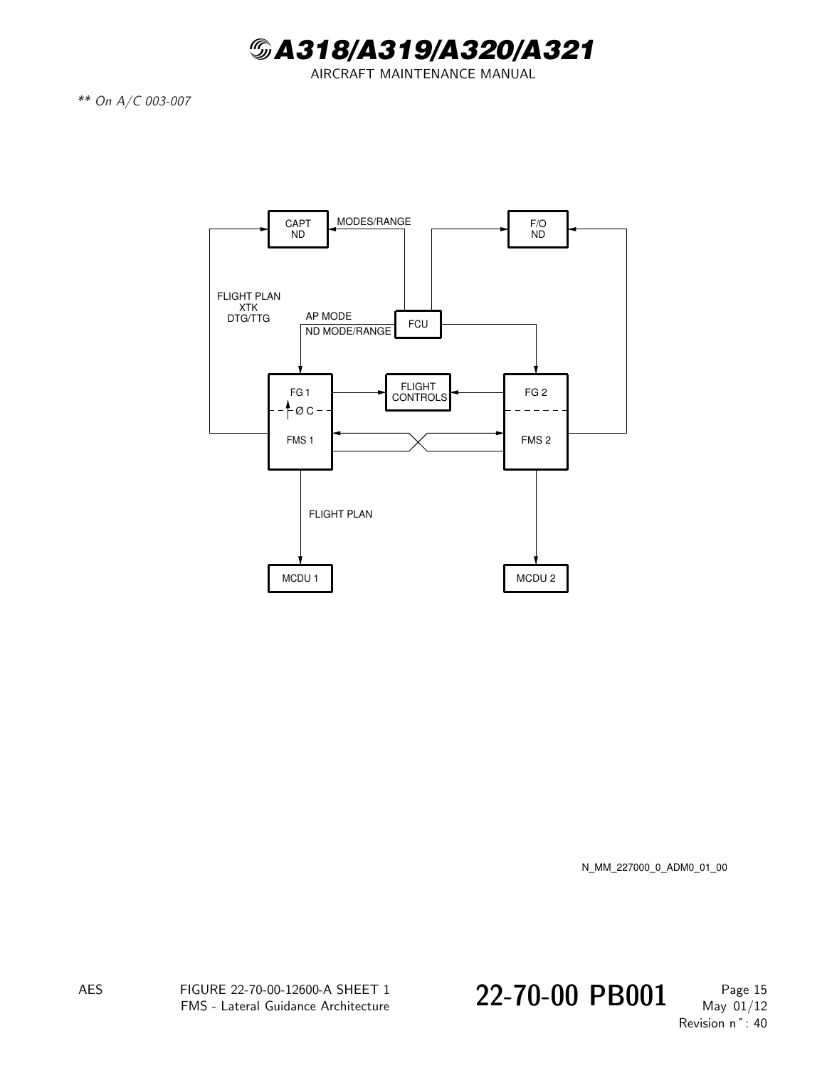
Figure 22-70-00-12600-A – FMS – Lateral Guidance Architecturep. 450
Figure 22-70-00-12700-A – FMS – Weight Architecturep. 451
Figure 22-70-00-12800-A – FMS – Predictions/Vertical Guidance Architecturep. 452
22-70-00 PB 001 CONF 02 – FLIGHT MANAGEMENT SYSTEM (FMS) – DESCRIPTION AND OPERATIONp. 453
Generalp. 453
System Descriptionp. 454
Operationp. 455
Figure 22-70-00-12300-A – FMS – General Architecturep. 464
Figure 22-70-00-12400-A – FMS – NAV Architecturep. 465
Figure 22-70-00-12500-A – FMS – RAD NAV Architecturep. 466
Figure 22-70-00-12600-A – FMS – Lateral Guidance Architecturep. 467
Figure 22-70-00-12700-A – FMS – Weight Architecturep. 468
Figure 22-70-00-12800-A – FMS – Predictions/Vertical Guidance Architecturep. 469
22-70-00 PB 301 CONF 00 – FLIGHT MANAGEMENT SYSTEM (FMS) – SERVICINGp. 470
22-70-00-610-006-A – Downloading of the FM Datap. 470
22-70-00-610-006-D – Downloading of the FM Datap. 473
22-70-00-610-008-A – Uploading of the FM Datap. 476
22-70-00-610-008-D – Uploading of the FM Datap. 479
22-70-00 PB 501 CONF 00 – FLIGHT MANAGEMENT SYSTEM (FMS) – ADJUSTMENT/TESTp. 482
22-70-00-710-001-A – Operational Test of the Multipurpose Control and Display Unit (MCDU)p. 482
22-70-00-710-002-A – Operational Test of the Initialization of the Flight Planp. 484
22-70-00-710-003-A – Operational Test of the Automatic Switching of the MCDUsp. 487
22-71 – FLIGHT PLAN/DATA BASEp. 489
22-71-00 – FLIGHT PLAN/DATA BASEp. 489
22-71-00 PB 001 CONF 00 – FLIGHT PLAN/DATA BASE – DESCRIPTION AND OPERATIONp. 489
Generalp. 489
System Descriptionp. 490
Figure 22-71-00-12500-A – Flight Plan in Cruisep. 519
Figure 22-71-00-12800-A – Path and Terminator (Sheet 1/4)p. 520
Figure 22-71-00-12900-A – Path and Terminator (Sheet 2/4)p. 521
Figure 22-71-00-13000-A – Path and Terminator (Sheet 3/4)p. 522
Figure 22-71-00-13100-A – Path and Terminator (Sheet 4/4)p. 523
Figure 22-71-00-13200-A – Discontinuity between the Termination Point of the Airway and First Point of the Approachp. 524
Figure 22-71-00-13300-A – Departure Segmentp. 525
Figure 22-71-00-13400-A – Arrival Segmentp. 526
Figure 22-71-00-13500-A – Flight Plan in Approachp. 527
Figure 22-71-00-13600-A – Flight Plan in Go Aroundp. 528
Figure 22-71-00-13800-A – Vertical Flight Plan Elementsp. 529
Figure 22-71-00-13900-A – Perf TAKEOFF Pagep. 530
Figure 22-71-00-14000-A – F-PLN A Pagep. 531
Figure 22-71-00-14100-A – Vertical Revision Pagep. 532
Figure 22-71-00-14200-A – Progress Page (On Descent)p. 533
Figure 22-71-00-14300-A – INIT Page Ap. 534
Figure 22-71-00-14400-A – Performance Approach Pagep. 535
Figure 22-71-00-14600-A – SEC INDEX Page (with no Defined Secondary F-PLN)p. 536
Figure 22-71-00-14700-A – Secondary F-PLN Page A at Originp. 537
Figure 22-71-00-15100-A – F-PLN Initializationp. 538
Figure 22-71-00-15200-A – Fuel Initializationp. 539
Figure 22-71-00-15400-A – No SEC F-PLN Existingp. 540
Figure 22-71-00-15500-A – SEC F-PLN Already Existingp. 541
Figure 22-71-00-15900-A – LAT REV Pagesp. 542
Figure 22-71-00-16100-A – Temporary F-PLNp. 543
Figure 22-71-00-16300-A – DEPARTURE Page 1p. 544
Figure 22-71-00-16400-A – DEPARTURE Page 2p. 545
Figure 22-71-00-16500-A – MCDU Mechanization (Sheet 1/3)p. 546
Figure 22-71-00-16600-A – MCDU Mechanization (Sheet 2/3)p. 547
Figure 22-71-00-16700-A – MCDU Mechanization (Sheet 3/3)p. 548
Figure 22-71-00-16900-A – ARRIVAL and APPROACH VIA Pagesp. 549
Figure 22-71-00-17000-A – MCDU Mechanization (Sheet 1/3)p. 550
Figure 22-71-00-17100-A – MCDU Mechanization (Sheet 2/3)p. 551
Figure 22-71-00-17200-A – MCDU Mechanization (Sheet 3/3)p. 552
Figure 22-71-00-17400-A – Next Waypointp. 553
Figure 22-71-00-17600-A – Offsetp. 554
Figure 22-71-00-17800-A – Holding Patternp. 555
Figure 22-71-00-18000-A – VIA/GO TOp. 556
Figure 22-71-00-18200-A – Alternatesp. 557
Figure 22-71-00-18500-A – DIR TOp. 558
Figure 22-71-00-19100-A – VERT REV Pages (with time constraint)p. 559
Figure 22-71-00-19200-A – Constraints and Step Insertion at CRZ Waypointp. 560
Figure 22-71-00-19600-A – WIND Pagep. 561
Figure 22-71-00-19700-A – Cruise Wind Entryp. 562
Figure 22-71-00-19800-A – F-PLN B Pagep. 563
Figure 22-71-00-19900-A – DES FORECAST Pagep. 564
Figure 22-71-00-20000-A – PERF APPR Pagep. 565
Figure 22-71-00-20400-A – DATA INDEX Pagep. 566
Figure 22-71-00-20700-A – A/C Status Pagep. 567
Figure 22-71-00-20900-A – NAVAID Pagep. 568
Figure 22-71-00-21000-A – STORED NAVAID Pagesp. 569
Figure 22-71-00-21100-A – NEW NAVAID Pagesp. 570
Figure 22-71-00-21200-A – WAYPOINT Pagesp. 571
Figure 22-71-00-21300-A – Place/Bearing/Distance and Place/Bearing-Place/Bearingp. 572
Figure 22-71-00-21400-A – STORED WAYPOINT Pagep. 573
Figure 22-71-00-21500-A – NEW WAYPOINT Pagesp. 574
Figure 22-71-00-21600-A – RUNWAY Pagep. 575
Figure 22-71-00-21700-A – STORED RUNWAY Pagep. 576
Figure 22-71-00-21800-A – NEW RUNWAY Pagep. 577
Figure 22-71-00-21900-A – HOLD Pagep. 578
Figure 22-71-00-22000-A – ROUTE Pagesp. 579
Figure 22-71-00-22100-A – STORED ROUTE Pagep. 580
Figure 22-71-00-22200-A – NEW ROUTE Pagep. 581
22-71-00 PB 001 CONF 02 – FLIGHT PLAN/DATA BASE – DESCRIPTION AND OPERATIONp. 582
Generalp. 582
System Descriptionp. 583
Figure 22-71-00-12500-A – Flight Plan in Cruisep. 612
Figure 22-71-00-12800-A – Path and Terminator (Sheet 1/4)p. 613
Figure 22-71-00-12900-A – Path and Terminator (Sheet 2/4)p. 614
Figure 22-71-00-13000-A – Path and Terminator (Sheet 3/4)p. 615
Figure 22-71-00-13100-A – Path and Terminator (Sheet 4/4)p. 616
Figure 22-71-00-13200-A – Discontinuity between the Termination Point of the Airway and First Point of the Approachp. 617
Figure 22-71-00-13300-A – Departure Segmentp. 618
Figure 22-71-00-13400-A – Arrival Segmentp. 619
Figure 22-71-00-13500-A – Flight Plan in Approachp. 620
Figure 22-71-00-13600-A – Flight Plan in Go Aroundp. 621
Figure 22-71-00-13800-A – Vertical Flight Plan Elementsp. 622
Figure 22-71-00-13900-A – Perf TAKEOFF Pagep. 623
Figure 22-71-00-14000-A – F-PLN A Pagep. 624
Figure 22-71-00-14100-A – Vertical Revision Pagep. 625
Figure 22-71-00-14200-A – Progress Page (On Descent)p. 626
Figure 22-71-00-14300-A – INIT Page Ap. 627
Figure 22-71-00-14400-A – Performance Approach Pagep. 628
Figure 22-71-00-14600-A – SEC INDEX Page (with no Defined Secondary F-PLN)p. 629
Figure 22-71-00-14700-A – Secondary F-PLN Page A at Originp. 630
Figure 22-71-00-15100-A – F-PLN Initializationp. 631
Figure 22-71-00-15200-A – Fuel Initializationp. 632
Figure 22-71-00-15400-A – No SEC F-PLN Existingp. 633
Figure 22-71-00-15500-A – SEC F-PLN Already Existingp. 634
Figure 22-71-00-15900-A – LAT REV Pagesp. 635
Figure 22-71-00-16100-A – Temporary F-PLNp. 636
Figure 22-71-00-16300-A – DEPARTURE Page 1p. 638
Figure 22-71-00-16400-A – DEPARTURE Page 2p. 639
Figure 22-71-00-16500-A – MCDU Mechanization (Sheet 1/3)p. 640
Figure 22-71-00-16600-A – MCDU Mechanization (Sheet 2/3)p. 641
Figure 22-71-00-16700-A – MCDU Mechanization (Sheet 3/3)p. 642
Figure 22-71-00-16900-A – ARRIVAL and APPROACH VIA Pagesp. 643
Figure 22-71-00-17000-A – MCDU Mechanization (Sheet 1/3)p. 644
Figure 22-71-00-17100-A – MCDU Mechanization (Sheet 2/3)p. 645
Figure 22-71-00-17200-A – MCDU Mechanization (Sheet 3/3)p. 646
Figure 22-71-00-17400-A – Next Waypointp. 647
Figure 22-71-00-17600-A – Offsetp. 648
Figure 22-71-00-17800-A – Holding Patternp. 649
Figure 22-71-00-18000-A – VIA/GO TOp. 650
Figure 22-71-00-18200-A – Alternatesp. 651
Figure 22-71-00-18500-A – DIR TOp. 652
Figure 22-71-00-19100-A – VERT REV Pages (with time constraint)p. 653
Figure 22-71-00-19200-A – Constraints and Step Insertion at CRZ Waypointp. 654
Figure 22-71-00-19600-A – WIND Pagep. 655
Figure 22-71-00-19700-A – Cruise Wind Entryp. 656
Figure 22-71-00-19800-A – F-PLN B Pagep. 657
Figure 22-71-00-19900-A – DES FORECAST Pagep. 658
Figure 22-71-00-20000-A – PERF APPR Pagep. 659
Figure 22-71-00-20400-A – DATA INDEX Pagep. 660
Figure 22-71-00-20700-A – A/C Status Pagep. 661
Figure 22-71-00-20900-A – NAVAID Pagep. 662
Figure 22-71-00-21000-A – STORED NAVAID Pagesp. 663
Figure 22-71-00-21100-A – NEW NAVAID Pagesp. 664
Figure 22-71-00-21200-A – WAYPOINT Pagesp. 665
Figure 22-71-00-21300-A – Place/Bearing/Distance and Place/Bearing-Place/Bearingp. 666
Figure 22-71-00-21400-A – STORED WAYPOINT Pagep. 667
Figure 22-71-00-21500-A – NEW WAYPOINT Pagesp. 668
Figure 22-71-00-21600-A – RUNWAY Pagep. 669
Figure 22-71-00-21700-A – STORED RUNWAY Pagep. 670
Figure 22-71-00-21800-A – NEW RUNWAY Pagep. 671
Figure 22-71-00-21900-A – HOLD Pagep. 672
Figure 22-71-00-22000-A – ROUTE Pagesp. 673
Figure 22-71-00-22100-A – STORED ROUTE Pagep. 674
Figure 22-71-00-22200-A – NEW ROUTE Pagep. 675
22-72 – NAVIGATION/LATERAL FUNCTIONSp. 676
22-72-00 – NAVIGATION/LATERAL FUNCTIONSp. 676
22-72-00 PB 001 CONF 00 – NAVIGATION/LATERAL FUNCTIONS – DESCRIPTION AND OPERATIONp. 676
Generalp. 676
System Descriptionp. 677
Figure 22-72-00-12500-A – General Navigation Computation Organizationp. 692
Figure 22-72-00-12700-A – Radio Positionsp. 693
Figure 22-72-00-12800-A – FMGC Positionp. 694
Figure 22-72-00-12900-A – Localizer Updatingp. 695
Figure 22-72-00-13000-A – Position Updatingp. 696
Figure 22-72-00-13100-A – Runway Takeoff Shift for Takeoff Position Updatingp. 697
Figure 22-72-00-13200-A – POSITION MONITOR Page Accessp. 698
Figure 22-72-00-13400-A – SELECTED NAVAID Pagep. 699
Figure 22-72-00-13600-A – Bearing/Distance to a Fixp. 700
Figure 22-72-00-14000-A – Navigation Mode Selectionp. 701
Figure 22-72-00-14300-A – Class of Navigationp. 702
Figure 22-72-00-14700-A – Radio Navigation Architecturep. 703
Figure 22-72-00-14900-A – RMP Selection-ND Displayp. 704
Figure 22-72-00-15100-A – Manual Selection through RADIO NAV Page and PROG Pagep. 705
Figure 22-72-00-15200-A – Manual Selection through MCDU-ND Displayp. 706
Figure 22-72-00-15700-A – IR Alignment Architecturep. 707
Figure 22-72-00-15900-A – Position Coordinates Entryp. 708
Figure 22-72-00-16300-A – Type I Transition CF, TFp. 709
Figure 22-72-00-16500-A – Type II Transitionp. 710
Figure 22-72-00-16600-A – Parallel Offset Capturep. 711
Figure 22-72-00-16700-A – Transitions to Holding Pattern : Determination of Entry Typep. 712
Figure 22-72-00-16800-A – Direct Entryp. 713
Figure 22-72-00-16900-A – Teardrop Entryp. 714
Figure 22-72-00-17000-A – Parallel Entryp. 715
Figure 22-72-00-17100-A – Type III Transition CF – VAp. 716
Figure 22-72-00-17200-A – Type IV and Type V Transitionsp. 717
Figure 22-72-00-17300-A – Leg Transition Typesp. 718
Figure 22-72-00-17800-A – Reference Parameters for a CF Legp. 719
Figure 22-72-00-17900-A – PF Leg (Procedure Turn)p. 720
Figure 22-72-00-18000-A – Reference Parameters Displayp. 721
Figure 22-72-00-18200-A – Lateral Path Error on Straight or Great Circle Pathp. 722
Figure 22-72-00-18300-A – Lateral Path Error on Circular Pathp. 723
Figure 22-72-00-18500-A – Along Track Distancep. 724
Figure 22-72-00-19000-A – NAV Engagementp. 725
Figure 22-72-00-19100-A – NAV Engagement Displayp. 726
Figure 22-72-00-19400-A – LAT REV Page and Perf APPR Pagep. 727
Figure 22-72-00-19500-A – ILS Precapturep. 728
Figure 22-72-00-19900-A – F-PLN Sequencingp. 729
Figure 22-72-00-20000-A – Holding Pattern Display on MCDUp. 730
Figure 22-72-00-20200-A – Holding Pattern Mechanization IMM EXITp. 731
Figure 22-72-00-20300-A – Holding Pattern Exit – MCDUp. 732
22-72-00 PB 001 CONF 01 – NAVIGATION/LATERAL FUNCTIONS – DESCRIPTION AND OPERATIONp. 733
Generalp. 733
22-72-00 PB 001 CONF 02 – NAVIGATION/LATERAL FUNCTIONS – DESCRIPTION AND OPERATIONp. 734
Generalp. 734
System Descriptionp. 735
Figure 22-72-00-12500-A – General Navigation Computation Organizationp. 750
Figure 22-72-00-12700-A – Radio Positionsp. 751
Figure 22-72-00-12800-A – FMGC Positionp. 752
Figure 22-72-00-12900-A – Localiser Updatingp. 753
Figure 22-72-00-13000-A – Position Updatingp. 754
Figure 22-72-00-13100-A – Runway Takeoff Shift for Takeoff Position Updatingp. 755
Figure 22-72-00-13200-A – POSITION MONITOR Page Accesp. 756
Figure 22-72-00-13400-A – SELECTED NAVAID Pagep. 757
Figure 22-72-00-13600-A – Bearing/Distance to a Fixp. 758
Figure 22-72-00-14000-A – Navigation Mode Selectionp. 759
Figure 22-72-00-14300-A – Class of Navigationp. 761
Figure 22-72-00-14700-A – Radio Navigation Architecturep. 762
Figure 22-72-00-14900-A – RMP Selection-ND Displayp. 763
Figure 22-72-00-15100-A – Manual Selection through RADIO NAV Page and PROG Pagep. 764
Figure 22-72-00-15200-A – Manual Selection through MCDU-ND Displayp. 765
Figure 22-72-00-15700-A – IR Alignment Architecturep. 766
Figure 22-72-00-15900-A – Position Coordinates Entryp. 767
Figure 22-72-00-16300-A – Type I Transition CF, TFp. 768
Figure 22-72-00-16500-A – Type II Transitionp. 769
Figure 22-72-00-16600-A – Parallel Offset Capturep. 770
Figure 22-72-00-16700-A – Transitions to Holding Pattern : Determination of Entry Typep. 771
Figure 22-72-00-16800-A – Direct Entryp. 772
Figure 22-72-00-16900-A – Teardrop Entryp. 773
Figure 22-72-00-17000-A – Parallel Entryp. 774
Figure 22-72-00-17100-A – Type III Transition CF – VAp. 775
Figure 22-72-00-17200-A – Type IV and Type V Transitionsp. 776
Figure 22-72-00-17300-A – Leg Transition Typesp. 777
Figure 22-72-00-17800-A – Leg Transition Typesp. 778
Figure 22-72-00-17900-A – PF Leg (Procedure Turn)p. 779
Figure 22-72-00-18000-A – Reference Parameters Displayp. 780
Figure 22-72-00-18200-A – Lateral Path Error on Straight or Great Circle Pathp. 781
Figure 22-72-00-18300-A – Lateral Path Error on Circular Pathp. 782
Figure 22-72-00-18500-A – Along Track Distancep. 783
Figure 22-72-00-19000-A – NAV Engagementp. 784
Figure 22-72-00-19100-A – NAV Engagement Displayp. 785
Figure 22-72-00-19400-A – LAT REV Page and Perf APPR Pagep. 786
Figure 22-72-00-19500-A – ILS Precapturep. 787
Figure 22-72-00-19900-A – F-PLN Sequencingp. 788
Figure 22-72-00-20000-A – Holding Pattern Display on MCDUp. 789
Figure 22-72-00-20200-A – Holding Pattern Mechanization IMM EXITp. 790
Figure 22-72-00-20300-A – Holding Pattern Exit – MCDUp. 791
22-73 – PERFORMANCE/VERTICAL FUNCTIONSp. 792
22-73-00 – PERFORMANCE/VERTICAL FUNCTIONSp. 792
22-73-00 PB 001 CONF 00 – PERFORMANCE/VERTICAL FUNCTIONS – DESCRIPTION AND OPERATIONp. 792
Generalp. 792
System Descriptionp. 793
Figure 22-73-00-12600-A – Vertical F-PLN Definitionp. 817
Figure 22-73-00-12700-A – Flight Phase Display on PERF and PROG Pagesp. 818
Figure 22-73-00-12900-A – Manual Activation of APPROACH Flight Phasep. 819
Figure 22-73-00-13300-A – F, S and VFTO Display on PERF Pagesp. 820
Figure 22-73-00-13400-A – ECON Speed/Mach Display on PERF Pagesp. 821
Figure 22-73-00-13500-A – Hold Speed Display (in Line 2)p. 822
Figure 22-73-00-13700-A – Manual Crossover Altitude Lawp. 823
Figure 22-73-00-14100-A – Display of Predictionsp. 824
Figure 22-73-00-14300-A – Display of Takeoff Parametersp. 825
Figure 22-73-00-14400-A – F-PLN Predictionsp. 826
Figure 22-73-00-14500-A – Takeoffp. 827
Figure 22-73-00-14600-A – Predicted CLIMB Profilep. 828
Figure 22-73-00-14700-A – Climb – Crossing the Speed Limit Altitudep. 829
Figure 22-73-00-14800-A – Level off for an Altitude Constraintp. 830
Figure 22-73-00-14900-A – Step Climbp. 831
Figure 22-73-00-15000-A – Display of Descent Parametersp. 832
Figure 22-73-00-15100-A – Theoretical Descent Profile Constructionp. 833
Figure 22-73-00-15200-A – Repressurization Segmentp. 834
Figure 22-73-00-15300-A – Return to Path Predictionsp. 835
Figure 22-73-00-15400-A – Consideration of HM Leg in Predictionsp. 836
Figure 22-73-00-15500-A – DES Mode: Aircraft on Profile, in SPEED AUTO CONTROLp. 837
Figure 22-73-00-15600-A – DES Mode: Aircraft on Idle Path, Underspeeding in SPEED AUTO CONTROLp. 838
Figure 22-73-00-15700-A – DES Mode: Aircraft above Profile – Hold of Upper Speed Margin in SPEED AUTO CONTROLp. 839
Figure 22-73-00-15800-A – DES Mode: Aircraft below Profile in SPEED AUTO CONTRLp. 840
Figure 22-73-00-15900-A – APPROACH Pages (APPR)p. 841
Figure 22-73-00-16000-A – Theoretical Approach Profilep. 842
Figure 22-73-00-16100-A – Theoretical Approach Profile with an Intermediate Altitude Constraintp. 843
Figure 22-73-00-16200-A – FINAL Mode (A/C on Approach Profile)p. 844
Figure 22-73-00-16400-A – Speed Preselection for Climb Phasep. 845
Figure 22-73-00-16500-A – Manual Speed Selection – Effect on Predictionsp. 846
Figure 22-73-00-16600-A – DES Mode in SPEED MANUAL CONTROL : Aircraft on Profilep. 847
Figure 22-73-00-16700-A – DES Mode in SPEED MANUAL CONTROL : Aircraft above Profilep. 848
Figure 22-73-00-16800-A – Display of SET SPD AUTO Message in Case of no Manual Speed Preselection for Next Phasep. 849
Figure 22-73-00-17000-A – Expedite in Climbp. 850
Figure 22-73-00-17100-A – V/S in Descent (Aircraft above Profile)p. 851
Figure 22-73-00-17300-A – Required Distance to Land – Distance to Destinationp. 852
Figure 22-73-00-17400-A – LATERAL MANUAL CONTROL in Descentp. 853
Figure 22-73-00-17800-A – Weight and Fuel Displayp. 854
Figure 22-73-00-18000-A – MCDU Display upon ENGINE OUTp. 855
Figure 22-73-00-18200-A – Fuel Predictions on F-PLN B and VERT REV pagesp. 856
Figure 22-73-00-18500-A – Performance Factorp. 857
Figure 22-73-00-18700-A – Overview of Alternatesp. 858
Figure 22-73-00-18900-A – PROG Pagep. 859
Figure 22-73-00-19100-A – Time and Fuel to Exit the Holdp. 860
22-73-00 PB 001 CONF 02 – PERFORMANCE/VERTICAL FUNCTIONS – DESCRIPTION AND OPERATIONp. 861
Generalp. 861
System Descriptionp. 862
Figure 22-73-00-12600-A – Vertical F-PLN Definitionp. 886
Figure 22-73-00-12700-A – Flight Phase Display on PERF and PROG Pagesp. 887
Figure 22-73-00-12900-A – Manual Activation of APPROACH Flight Phasep. 888
Figure 22-73-00-13300-A – F, S and VFTO Display on PERF Pagesp. 889
Figure 22-73-00-13400-A – ECON Speed2/Mach Display on PERF Pagesp. 890
Figure 22-73-00-13500-A – Hold Speed Display (in Line 2)p. 891
Figure 22-73-00-13700-A – Manual Crossover Altitude Lawp. 892
Figure 22-73-00-14100-A – Display of Predictionsp. 893
Figure 22-73-00-14300-A – Display of Takeoff Parametersp. 894
Figure 22-73-00-14400-A – F-PLN Predictionsp. 895
Figure 22-73-00-14500-A – Takeoffp. 896
Figure 22-73-00-14600-A – Predicted CLIMB Profilep. 897
Figure 22-73-00-14700-A – Climb – Crossing the Speed Limit Altitudep. 898
Figure 22-73-00-14800-A – Level off for an Altitude Constraintp. 900
Figure 22-73-00-14900-A – Step Climbp. 901
Figure 22-73-00-15000-A – Display of Descent Parametersp. 902
Figure 22-73-00-15100-A – Theoretical Descent Profile Constructionp. 903
Figure 22-73-00-15200-A – Repressurization Segmentp. 904
Figure 22-73-00-15300-A – Return to Path Predictionsp. 905
Figure 22-73-00-15400-A – Consideration of HM Leg in Predictionsp. 906
Figure 22-73-00-15500-A – DES Mode: Aircraft on Profile, in SPEED AUTO CONTROLp. 907
Figure 22-73-00-15600-A – DES Mode: Aircraft on Idle Path, Underspeeding in SPEED AUTO CONTROLp. 908
Figure 22-73-00-15700-A – DES Mode: Aircraft above Profile – Hold of Upper Speed Margin in SPEED AUTO CONTROLp. 909
Figure 22-73-00-15800-A – DES Mode: Aircraft below Profile in SPEED AUTO CONTROLp. 910
Figure 22-73-00-15900-A – APPROACH Pages (APPR)p. 911
Figure 22-73-00-16000-A – Theoretical Approach Profilep. 912
Figure 22-73-00-16100-A – Theoretical Approach Profile with an Intermediate Altitude Constraintp. 913
Figure 22-73-00-16200-A – FINAL Mode (A2/C on Approach Profile)p. 914
Figure 22-73-00-16400-A – Speed Preselection for Climb Phasep. 915
Figure 22-73-00-16500-A – Manual Speed Selection – Effect on Predictionsp. 916
Figure 22-73-00-16600-A – DES Mode in SPEED MANUAL CONTROL : Aircraft on Profilep. 917
Figure 22-73-00-16700-A – DES Mode in SPEED MANUAL CONTROL : Aircraft above Profilep. 918
Figure 22-73-00-16800-A – Display of SET SPD AUTO Message in Case of no Manual Speed Preselection for Next Phasep. 919
Figure 22-73-00-17000-A – Expedite in Climbp. 920
Figure 22-73-00-17100-A – V2/S in Descent (Aircraft above Profile)p. 921
Figure 22-73-00-17300-A – Required Distance to Land – Distance to Destinationp. 922
Figure 22-73-00-17400-A – LATERAL MANUAL CONTROL in Descentp. 923
Figure 22-73-00-17800-A – Weight and Fuel Displayp. 924
Figure 22-73-00-18000-A – MCDU Display upon ENGINE OUTp. 925
Figure 22-73-00-18200-A – Fuel Predictions on F-PLN B and VERT REV pagesp. 926
Figure 22-73-00-18500-A – Performance Factorp. 927
Figure 22-73-00-18700-A – Overview of Alternatesp. 928
Figure 22-73-00-18900-A – PROG Pagep. 929
Figure 22-73-00-19100-A – Time and Fuel to Exit the Holdp. 930
22-74 – OPERATIONAL USEp. 931
22-74-00 – OPERATIONAL USEp. 931
22-74-00 PB 001 CONF 00 – OPERATIONAL USE – DESCRIPTION AND OPERATIONp. 931
Generalp. 931
System Descriptionp. 932
Figure 22-74-00-11200-A – MCDU Front Panelp. 953
Figure 22-74-00-11200-B – MCDU Front Panelp. 954
Figure 22-74-00-13200-A – Horizontal and Vertical Slewingp. 955
Figure 22-74-00-13500-A – Example of Displayp. 956
Figure 22-74-00-14000-A – Page Hierarchy (Sheet 1/6)p. 957
Figure 22-74-00-14100-A – Page Hierarchy (Sheet 2/6)p. 958
Figure 22-74-00-14200-A – Page Hierarchy (Sheet 3/6)p. 959
Figure 22-74-00-14300-A – Page Hierarchy (Sheet 4/6)p. 960
Figure 22-74-00-14400-A – Page Hierarchy (Sheet 5/6)p. 961
Figure 22-74-00-14500-A – Page Hierarchy (Sheet 6/6)p. 962
Figure 22-74-00-15300-A – Examples of Messages (MCDU & EIS)p. 963
Figure 22-74-00-16000-A – Message Queue Operationp. 964
22-74-00 PB 001 CONF 02 – OPERATIONAL USE – DESCRIPTION AND OPERATIONp. 965
Generalp. 965
System Descriptionp. 966
Figure 22-74-00-11200-A – MCDU Front Panelp. 986
Figure 22-74-00-13200-A – Horizontal and Vertical Slewingp. 987
Figure 22-74-00-13500-A – Example of Displayp. 988
Figure 22-74-00-14000-A – Page Hierarchy (Sheet 1/6)p. 989
Figure 22-74-00-14100-A – Page Hierarchy (Sheet 2/6)p. 990
Figure 22-74-00-14200-A – Page Hierarchy (Sheet 3/6)p. 991
Figure 22-74-00-14300-A – Page Hierarchy (Sheet 4/6)p. 992
Figure 22-74-00-14400-A – Page Hierarchy (Sheet 5/6)p. 994
Figure 22-74-00-14500-A – Page Hierarchy (Sheet 6/6)p. 996
Figure 22-74-00-15300-A – Examples of Messages (MCDU & EIS)p. 997
Figure 22-74-00-16000-A – Message Queue Operationp. 998
22-75 – EIS DISPLAYSp. 999
22-75-00 – EIS DISPLAYSp. 999
22-75-00 PB 001 CONF 00 – EIS DISPLAYS – DESCRIPTION AND OPERATIONp. 999
Generalp. 999
System Descriptionp. 1000
Figure 22-75-00-11200-A – FMGC – EIS Interfacep. 1010
Figure 22-75-00-11300-A – Different Modes on NDp. 1011
Figure 22-75-00-12700-A – ARC Mode EDIT Areap. 1012
Figure 22-75-00-12900-A – ROSE-NAV Mode EDIT Areap. 1013
Figure 22-75-00-13100-A – PLAN Mode EDIT Areap. 1014
Figure 22-75-00-14500-A – Flight Plan Examplesp. 1015
Figure 22-75-00-14600-A – Offset Pathp. 1016
Figure 22-75-00-15300-A – Pseudo Waypoints on the NDp. 1017
22-75-00 PB 001 CONF 02 – EIS DISPLAYS – DESCRIPTION AND OPERATIONp. 1018
Generalp. 1018
System Descriptionp. 1019
Figure 22-75-00-11200-A – FMGC – EIS Interfacep. 1029
Figure 22-75-00-11300-A – Different Modes on NDp. 1030
Figure 22-75-00-12700-A – ARC Mode EDIT Areap. 1031
Figure 22-75-00-13000-A – ROSE-NAV Mode EDIT Areap. 1032
Figure 22-75-00-13200-A – PLAN Mode EDIT Areap. 1033
Figure 22-75-00-14600-A – Flight Plan Examplesp. 1034
Figure 22-75-00-14700-A – Offset Pathp. 1035
Figure 22-75-00-15400-A – Pseudo Waypoints on the NDp. 1036
22-76 – DATA LINK AND PRINTER FUNCTIONSp. 1037
22-76-00 – DATA LINK AND PRINTER FUNCTIONSp. 1037
22-76-00 PB 001 CONF 00 – DATA LINK AND PRINTER FUNCTIONS – DESCRIPTION AND OPERATIONp. 1037
Generalp. 1037
System Descriptionp. 1038
Figure 22-76-00-13000-A – ACARS Flight Plan Initialization – MCDU Operation Nav Data Base Company Route Entriesp. 1052
Figure 22-76-00-13100-A – ACARS Flight Plan Initialization – MCDU Operation Downlink Request Initializationp. 1053
Figure 22-76-00-13200-A – ACARS Flight Plan Initialization – MCDU Operation Flight Plan Uplink Received After Engine Startp. 1054
Figure 22-76-00-13300-A – MCDU – ACARS Takeoff Datap. 1055
Figure 22-76-00-13400-A – UPLINK TO DATA REQ Page (with Default Values)p. 1056
Figure 22-76-00-13700-A – UPLINK FLX TO DATA Page (with Uplinked Data Not Inserted)p. 1057
Figure 22-76-00-13800-A – UPLINK MAX TO DATA page (with Uplinked Data Inserted)p. 1058
Figure 22-76-00-14000-A – CLIMB WIND Page (without Uplinked Data)p. 1059
Figure 22-76-00-14100-A – CRUISE WIND Page (with Wind Request Pending)p. 1060
Figure 22-76-00-14200-A – CLIMB WIND Page (after Reception of Wind Data)p. 1061
Figure 22-76-00-14400-A – REPORT Page (Prompt for Downlink of Position Report)p. 1062
Figure 22-76-00-16400-A – DATA INDEX (with ACARS installed)p. 1063
Figure 22-76-00-16500-A – PRINT FUNCTION Page 1 (with ACARS Takeoff Data Uplink Disabled and Auto Print of Wind Uplink Disabled)p. 1064
Figure 22-76-00-16600-A – PRINT FUNCTION Page 2 (with Auto Print at Transition to Takeoff Disabled and Pre-Flight Report Available)p. 1065
Figure 22-76-00-16700-A – ACARS FUNCTION Page (with Takeoff Data Function Disabled)p. 1066
Figure 22-76-00-16800-A – ACARS FUNCTION Page (with Position Downlink Report Disabled)p. 1067
22-76-00 PB 001 CONF 02 – DATA LINK AND PRINTER FUNCTIONS – DESCRIPTION AND OPERATIONp. 1068
Generalp. 1068
System Descriptionp. 1069
Figure 22-76-00-13000-A – ACARS Flight Plan Initialization – MCDU Operation Nav Data Base Company Route Entriesp. 1083
Figure 22-76-00-13100-A – ACARS Flight Plan Initialization – MCDU Operation Downlink Request Initializationp. 1084
Figure 22-76-00-13200-A – ACARS Flight Plan Initialization – MCDU Operation Flight Plan Uplink Received After Engine Startp. 1085
Figure 22-76-00-13300-A – MCDU – ACARS Takeoff Datap. 1086
Figure 22-76-00-13400-A – UPLINK TO DATA REQ Page (with Default Values)p. 1087
Figure 22-76-00-13700-A – UPLINK FLX TO DATA Page (with Uplinked Data Not Inserted)p. 1088
Figure 22-76-00-13800-A – UPLINK MAX TO DATA page (with Uplinked Data Inserted)p. 1089
Figure 22-76-00-14000-A – CLIMB WIND Page (without Uplinked Data)p. 1090
Figure 22-76-00-14100-A – CRUISE WIND Page (with Wind Request Pending)p. 1091
Figure 22-76-00-14200-A – CLIMB WIND Page (after Reception of Wind Data)p. 1092
Figure 22-76-00-14400-A – REPORT Page (Prompt for Downlink of Position Report)p. 1093
Figure 22-76-00-16400-A – DATA INDEX (with ACARS installed)p. 1094
Figure 22-76-00-16500-A – PRINT FUNCTION Page 1 (with ACARS Takeoff Data Uplink Disabled and Auto Print of Wind Uplink Disabled)p. 1095
Figure 22-76-00-16600-A – PRINT FUNCTION Page 2 (with Auto Print at Transition to Takeoff Disabled and Pre-Flight Report Available)p. 1096
Figure 22-76-00-16700-A – ACARS FUNCTION Page (with Takeoff Data Function Disabled)p. 1097
Figure 22-76-00-16800-A – ACARS FUNCTION Page (with Position Downlink Report Disabled)p. 1098
22-81 – FLIGHT CONTROL UNIT (FCU)p. 1099
22-81-00 – FLIGHT CONTROL UNIT (FCU)p. 1099
22-81-00 PB 001 CONF 00 – FLIGHT CONTROL UNIT (FCU) – DESCRIPTION AND OPERATIONp. 1099
Generalp. 1099
Component Locationp. 1100
Component Descriptionp. 1101
System Descriptionp. 1102
Figure 22-81-00-12400-B – Flight Control Unit (FCU)p. 1106
Figure 22-81-00-12500-A – FCU – Component Locationp. 1107
Figure 22-81-00-12600-A – FCU – Internal Arrangementp. 1108
Figure 22-81-00-12600-B – FCU – Internal Arrangementp. 1109
Figure 22-81-00-14300-A – FCU – Architecturep. 1110
Figure 22-81-00-14300-B – FCU – Architecturep. 1111
Figure 22-81-00-17600-A – Monitoring of FCU by FMGCp. 1112
Figure 22-81-00-17700-A – Changeoverp. 1113
Figure 22-81-00-17700-B – Control of the FCU in Normal Operationp. 1114
22-81-12 – CONTROL UNIT – FLIGHT (FCU)p. 1115
22-81-12 PB 401 CONF 00 – CONTROL UNIT – FLIGHT (FCU) – REMOVAL/INSTALLATIONp. 1115
22-81-12-000-001-A – Removal of the FCUp. 1115
Figure 22-81-12-991-00200-A – Flight Control Unit (FCU)p. 1117
22-81-12-400-001-A – Installation of the FCUp. 1118
22-82 – MULTIPURPOSE CONTROL AND DISPLAY UNIT (MCDU)p. 1120
22-82-00 – MULTIPURPOSE CONTROL AND DISPLAY UNIT (MCDU)p. 1120
22-82-00 PB 001 CONF 00 – MULTIPURPOSE CONTROL AND DISPLAY UNIT (MCDU) – DESCRIPTION AND OPERATIONp. 1120
Generalp. 1120
Component Locationp. 1121
Component Descriptionp. 1122
Operationp. 1125
Figure 22-82-00-11200-A – MCDU Interfacep. 1127
Figure 22-82-00-12500-A – MCDU – Component Locationp. 1128
Figure 22-82-00-14000-A – MCDU Front Panelp. 1129
Figure 22-82-00-14000-B – MCDU Front Panelp. 1130
Figure 22-82-00-14400-A – MCDU – Functional Layoutp. 1131
Figure 22-82-00-14500-A – MCDU Componentsp. 1132
Figure 22-82-00-14600-A – MCDU – Block Diagramp. 1133
Figure 22-82-00-16000-A – Functioningp. 1134
Figure 22-82-00-16400-A – MCDU Switching Logicp. 1135
22-82-12 – CONTROL AND DISPLAY UNIT – MULTIPURPOSE (MCDU)p. 1136
22-82-12 PB 401 CONF 00 – CONTROL AND DISPLAY UNIT – MULTIPURPOSE (MCDU) – REMOVAL/INSTALLATIONp. 1136
22-82-12-000-001-A – Removal of the MCDUp. 1136
Figure 22-82-12-991-00100-A – Multipurpose Control and Display Unit (MCDU)p. 1138
22-82-12-400-002-A – Installation of the MCDUp. 1139
22-82-12 PB 701 CONF 00 – CONTROL AND DISPLAY UNIT – MULTIPURPOSE (MCDU) – CLEANING/PAINTINGp. 1142
22-82-12-100-001-A – Cleaning of the Multipurpose Control Display Unit (MCDU)p. 1142
22-83 – FLIGHT MANAGEMENT AND GUIDANCE COMPUTER (FMGC)p. 1144
22-83-00 – FLIGHT MANAGEMENT AND GUIDANCE COMPUTER (FMGC)p. 1144
22-83-00 PB 001 CONF 00 – FLIGHT MANAGEMENT AND GUIDANCE COMPUTER (FMGC) – DESCRIPTION AND OPERATIONp. 1144
Generalp. 1144
Component Locationp. 1145
System Descriptionp. 1146
Figure 22-83-00-11200-A – FMGC – Front Panelp. 1152
Figure 22-83-00-11300-B – FMGC – Internal Arrangement (Standard B and Common Standard)p. 1153
Figure 22-83-00-12600-A – FMGC – Component Locationp. 1154
Figure 22-83-00-15100-A – FMGC – Architecturep. 1155
Figure 22-83-00-15200-A – Power Supply Unitp. 1156
Figure 22-83-00-15300-A – Connector FMGCp. 1157
22-83-34 – COMPUTER – FLIGHT MANAGEMENT AND GUIDANCE (FMGC)p. 1158
22-83-34 PB 401 CONF 00 – COMPUTER – FLIGHT MANAGEMENT AND GUIDANCE (FMGC) – REMOVAL/INSTALLATIONp. 1158
22-83-34-000-001-A – Removal of the FMGCp. 1158
Figure 22-83-34-991-00100-A – Flight Management and Guidance Computer (FMGC)p. 1160
22-83-34-400-001-A – Installation of the FMGCp. 1161
22-83-34-400-001-D – Installation of the FMGCp. 1164
22-84 – FMGS: ELECTRICAL POWER SUPPLYp. 1167
22-84-00 – FMGS: ELECTRICAL POWER SUPPLYp. 1167
22-84-00 PB 001 CONF 00 – FMGS: ELECTRICAL POWER SUPPLY – DESCRIPTION AND OPERATIONp. 1167
Location of Circuit Breakersp. 1167
System Descriptionp. 1168
Figure 22-84-00-12600-A – Power Supply of FMGCsp. 1170
Figure 22-84-00-13100-A – Power Supply of FCUp. 1171
Figure 22-84-00-13800-A – MCDUs and Data Loader – Power Supplyp. 1172
Figure 22-84-00-13800-B – MCDUs – Power Supplyp. 1173
22-85 – FMGS: DISCRETE/ANALOG INTERFACESp. 1174
22-85-00 – FMGS: DISCRETE/ANALOG INTERFACESp. 1174
22-85-00 PB 001 CONF 00 – FMGS: DISCRETE/ANALOG INTERFACES – DESCRIPTION AND OPERATIONp. 1174
Generalp. 1174
Discrete Signalsp. 1175
22-86 – FMGS: BUS INTERFACESp. 1179
22-86-00 – FMGS: BUS INTERFACESp. 1179
22-86-00 PB 001 CONF 00 – FMGS: BUS INTERFACES – DESCRIPTION AND OPERATIONp. 1179
Generalp. 1179
ARINC Interconnectionsp. 1180
22-91 – FAULT ISOLATION FUNCTION – PRINCIPLEp. 1215
22-91-00 – FAULT ISOLATION FUNCTION – PRINCIPLEp. 1215
22-91-00 PB 001 CONF 00 – FAULT ISOLATION FUNCTION – PRINCIPLE – DESCRIPTION AND OPERATIONp. 1215
Generalp. 1215
Component Locationp. 1216
System Descriptionp. 1217
FIDS Power Supplyp. 1228
FIDS Interfacep. 1229
Operationp. 1230
Safety Testsp. 1233
Figure 22-91-00-13100-A – Component Locationp. 1234
Figure 22-91-00-15100-A – Functional Block Diagramp. 1235
Figure 22-91-00-15600-A – Fault Detectionp. 1236
Figure 22-91-00-15700-A – 1st Phase Analysis – FAC, FG and FM BITE levelsp. 1237
Figure 22-91-00-15800-A – Fault Detection – 1st and 2nd Phase Analysisp. 1238
Figure 22-91-00-15900-A – 3rd Phase Analysis (Update of CD)p. 1239
Figure 22-91-00-16100-A – AFS – MAIN MENU Pagep. 1240
Figure 22-91-00-16200-A – LAST LEG and PREVIOUS LEG REPORTS/TSD Pagesp. 1241
Figure 22-91-00-16300-A – LRU Identification Pagesp. 1242
Figure 22-91-00-16400-A – MCDU Pages MAIN MENU and Ground Scan Optionsp. 1243
Figure 22-91-00-19600-A – FIDS – BITE Interfacep. 1244
Figure 22-91-00-21700-A – Menu Chainingp. 1245
Figure 22-91-00-21800-A – Example of LAST LEG REPORT Utilization (1)p. 1246
Figure 22-91-00-21900-A – Example of LAST LEG REPORT Utilization (2)p. 1247
Figure 22-91-00-22000-A – Example of LAST LEG REPORT Utilization (3)p. 1248
22-91-00 PB 501 CONF 00 – FAULT ISOLATION FUNCTION – PRINCIPLE – ADJUSTMENT/TESTp. 1249
22-91-00-710-001-A – Ground Scanning of the AFSp. 1249
22-92 – AFS FAULT ISOLATIONp. 1252
22-92-00 – AFS FAULT ISOLATIONp. 1252
22-92-00 PB 001 CONF 00 – AFS FAULT ISOLATION – DESCRIPTION AND OPERATIONp. 1252
Generalp. 1252
22-96 – AFS TESTp. 1259
22-96-00 – AFS TESTp. 1259
22-96-00 PB 001 CONF 00 – AFS TEST – DESCRIPTION AND OPERATIONp. 1259
Generalp. 1259
Triggering of the AFS TESTp. 1260
Execution of the AFS TEST in the FIDSp. 1261
Execution of the LRU TEST in the FACp. 1262
Execution of the LRU TEST in the FMGCp. 1263
Operationp. 1264
Power-up Tests Initialization and Cockpit Repercussionsp. 1265
Figure 22-96-00-18000-A – Example of AFS TEST Utilization (1)p. 1266
Figure 22-96-00-18100-A – Example of AFS TEST Utilization (2)p. 1267
22-96-00 PB 501 CONF 00 – AFS TEST – ADJUSTMENT/TESTp. 1268
22-96-00-710-001-A – Operational Test of the AFSp. 1268
22-97 – LAND CAT III CAPABILITY TESTp. 1271
22-97-00 – LAND CAT III CAPABILITY TESTp. 1271
22-97-00 PB 001 CONF 00 – LAND CAT III CAPABILITY TEST – DESCRIPTION AND OPERATIONp. 1271
Generalp. 1271
System Descriptionp. 1272
Figure 22-97-00-13200-B – Land Test (Accepted)p. 1273
Figure 22-97-00-13300-A – Land Test (Refused)p. 1274
22-97-00 PB 501 CONF 00 – LAND CAT III CAPABILITY TEST – ADJUSTMENT/TESTp. 1275
22-97-00-710-001-A – Operational Test of the LAND CAT III Capabilityp. 1275
Chapter 23 – COMMUNICATIONS
Chapter 24 – ELECTRICAL POWER
Chapter 25 – EQUIPMENT/FURNISHINGS
Chapter 26 – FIRE PROTECTION
Chapter 27 – FLIGHT CONTROLS
Chapter 28 – FUEL
Chapter 29 – HYDRAULIC POWER
Chapter 30 – ICE AND RAIN PROTECTION
Chapter 31 – INDICATING/RECORDING SYSTEMS
Chapter 32 – LANDING GEAR
Chapter 33 – LIGHTS
Chapter 34 – NAVIGATION
Chapter 35 – OXYGEN
Chapter 36 – PNEUMATIC
Chapter 38 – WATER/WASTE
Chapter 46 – INFORMATION SYSTEMS
Chapter 49 – AIRBORNE AUXILIARY POWER
Chapter 51 – STANDARDS PRACTICES AND STRUCTURES
Chapter 52 – DOORS
Chapter 53 – FUSELAGE
Chapter 54 – NACELLES/PYLONS
Chapter 55 – STABILIZERS
Chapter 56 – WINDOWS
Chapter 57 – WINGS
Chapter 70 – (IAE) – STANDARD PRACTICES – ENGINE
Chapter 71 – (IAE) – POWER PLANT
Chapter 72 – (IAE) – ENGINE
Chapter 73 – (IAE) – ENGINE FUEL AND CONTROL
Chapter 74 – (IAE) – IGNITION
Chapter 75 – (IAE) – AIR
Chapter 76 – (IAE) – ENGINE CONTROLS
Chapter 77 – (IAE) – ENGINE INDICATING
Chapter 78 – (IAE) – EXHAUST
Chapter 79 – (IAE) – OIL
Chapter 80 – (IAE) – STARTING

Vertical and performance functions include flight phases, takeoff parameters, climb and descent predictions, altitude constraints, step climb, theoretical descent and approach profiles, speed-selection effects, fuel and weight displays, engine-out display functions and fuel predictions. This gives the A318 A319 A320 A321 Chapter 22 Auto Flight manual strong value for technicians who need to understand not merely an individual component but the information flow and functional relationships throughout the FMGS.

Maintenance, Component Replacement and System Testing

The manual contains practical component-maintenance tasks as well as descriptive material. Removal and installation procedures are provided for components including the rudder-trim control switch, RUD TRIM/RESET pushbutton switch, rudder-trim indicator, Flight Augmentation Computer, Flight Control Unit, Multipurpose Control and Display Unit and Flight Management and Guidance Computer. The MCDU section also includes a cleaning procedure.

Operational and adjustment/test material addresses numerous Auto Flight functions. Examples include tests of takeover and priority pushbuttons, autopilot disengagement and locking devices, vertical-speed and heading-hold modes, FCU lighting, FCU indicators and displays, altitude alert warning, FAC functions, rudder travel limiting, rudder trim, yaw damper and MCDU functions. The AFS test chapter explains computer safety-test information, discrete and ARINC input checks, plausibility testing, MCDU test reporting and troubleshooting information. LAND CAT III capability testing is also included as a dedicated section.

Fault Isolation and BITE Information

For troubleshooting work, Chapter 22 includes dedicated fault-isolation material rather than limiting the technician to system theory. The Fault Isolation Function section describes detection and analysis principles, FAC and FMGC BITE levels, report pages, LRU identification, ground scanning and examples of report utilization. The separate AFS Fault Isolation and AFS Test sections extend that workflow with system integrity testing after LRU replacement and test-result analysis through the MCDU.

This combination of functional diagrams, system logic and diagnostic information is particularly useful when a maintenance action requires understanding which computer or interface participates in a function before a component is removed or a test is run.

Instant PDF Maintenance Reference

The Airbus A318 A319 A320 A321 Chapter 22 Auto Flight Aircraft Maintenance Manual – Revision 40 2012 supports detailed work on autopilot and flight-director functions, autothrust, FAC-controlled augmentation functions, flight management and guidance, FCU and MCDU equipment, FMGC installations, system interfaces, operational tests and AFS fault-isolation tasks. Using the documented architecture, procedures, tests and control-system information helps technicians follow the specific Chapter 22 maintenance sequence rather than relying on generalized system descriptions. The manual is delivered as an instant PDF after purchase, with no physical shipping required; it can be opened on compatible computers, tablets or phones and printed as needed for workshop or reference use.
Reviews

There are no reviews yet.

Be the first to review “Airbus A318 A319 A320 A321 Chapter 22 Auto Flight Aircraft Maintenance Manual – Revision 40 2012”

What Our Customers Say

★★★★★ Live reviews from customers
Loading customer reviews...
0
    0
    Your Cart
    Your cart is emptyReturn to Shop
    🛒
    Recently Purchased
    🕒 verified order