
Airbus A340-200 A340-300 Aircraft Characteristics Airport and Maintenance Planning Manual PDF
Original price was: $39.95.$23.95Current price is: $23.95.
The complete Airbus A340-200/-300 Aircraft Characteristics (AC) manual for airport and maintenance planning – Revision 27, April 2020. 400+ pages of dimensions, ground clearances, turning radii, pavement data, servicing connections, engine exhaust contours, and jacking information for both the A340-200 and A340-300 with CFM56-5C engines.
Description
File Details
- Manual type: Aircraft Characteristics – Airport and Maintenance Planning (AC)
- Manufacturer: Airbus
- Models covered: A340-200 and A340-300 (basic versions, all weight variants)
- Engines covered: CFM56-5C2, CFM56-5C3, CFM56-5C4 (CFM56-5C series)
- APU covered: Garrett GTCP 331-350C (and 331-600 reference)
- Language: English
- Page count: 404 pages
- File format: PDF
- Revision: Revision No. 27
- Revision date: Apr 01/20
Chapters Covered
- Chapter 1 – Scope: Purpose and glossary of abbreviations and design weight terminology
- Chapter 2 – Aircraft Description: General aircraft characteristics data, dimensions, ground clearances, interior arrangements (plan view and cross-section), lower deck cargo compartments, door clearances, escape slides, landing gear, exterior lighting, antennas and probes, engine and nacelle, auxiliary power unit, levelling/symmetry/alignment, jacking for maintenance, jacking of the landing gear, support of aircraft
- Chapter 3 – Aircraft Performance: General information, payload/range ISA conditions, take-off weight limitation ISA conditions, take-off weight limitation ISA +15C, landing field length ISA conditions, final approach speed
- Chapter 4 – Ground Maneuvering: Turning radii, minimum turning radii, visibility from cockpit, runway and taxiway turn paths (135, 90, 180 degrees), runway holding bay, minimum line-up distance corrections, aircraft mooring
- Chapter 5 – Terminal Servicing: Servicing arrangements, symbols, typical ramp layouts (open apron and gate), full servicing turn-round time, minimum servicing turn-round time, ground service connections layout, grounding points, hydraulic/electrical/oxygen/fuel/pneumatic/oil/potable water/waste water systems, cargo control panels, engine starting pneumatic requirements, ground pneumatic power requirements, preconditioned airflow requirements, ground towing requirements, de-icing and external cleaning
- Chapter 6 – Operating Conditions: Engine exhaust velocities and temperatures contours (ground idle, breakaway, takeoff power), danger areas of engines, APU exhaust velocities and temperatures
- Chapter 7 – Pavement Data: Landing gear footprint, maximum pavement loads, landing gear loading on pavement, flexible pavement requirements (US Army Corps of Engineers), rigid pavement requirements (PCA), ACN/PCN reporting system
- Chapter 8 – Scaled Drawings
- Chapter 10 – Aircraft Rescue and Fire Fighting: Hazardous materials, batteries location, crew rest compartments, wheel/brake overheat, composite materials location, ground lock safety devices, emergency evacuation devices, doors and exits, cargo doors, control panels, APU compartment access, ground clearances, structural break-in points
The Airbus A340-200 A340-300 Aircraft Characteristics Airport and Maintenance Planning Manual PDF is the reference Airbus publishes for everyone who has to plan around the physical aircraft rather than fly it. Every diagram, table, and clearance figure in the document comes from the manufacturer and is grouped by chapter so an airport planner, a line maintenance engineer, or an MRO facility designer can jump straight to the number they need. The turnaround charts, ground service connection layout, and pavement data are all built around the actual geometry of the A340-200 and A340-300, not a generic widebody approximation.
What This Manual Delivers
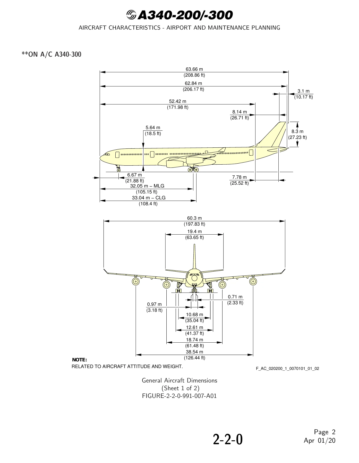
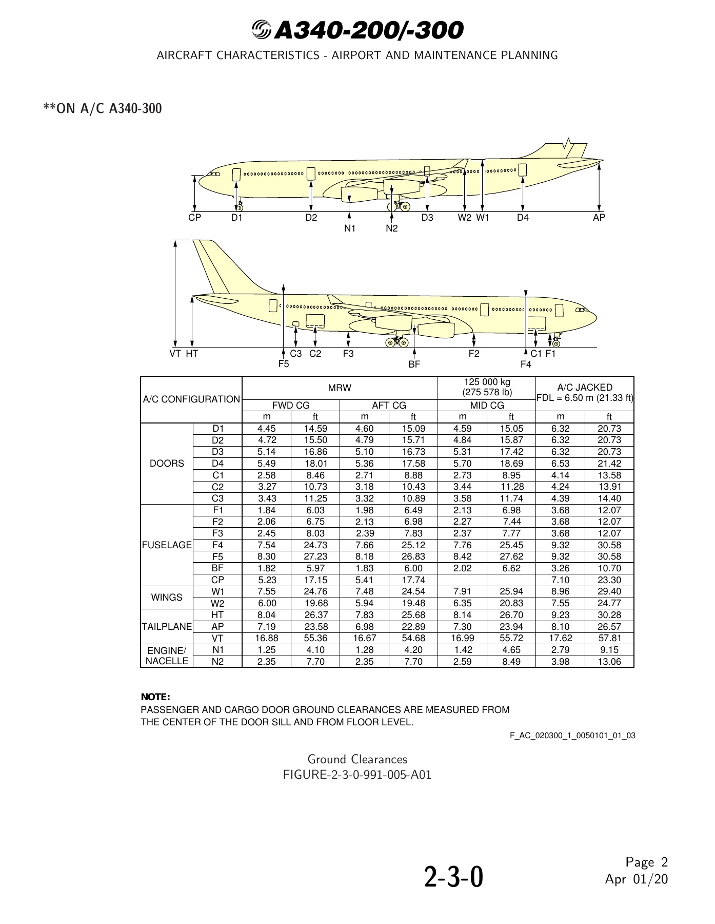
Open the file and the first thing you get is a full set of general aircraft dimensions for both models – overall length, wingspan, tail height, wheelbase, track, and every door position on the fuselage. Ground clearance tables then break that down for forward, aft, and mid CG, at maximum ramp weight and in a jacked maintenance configuration. Passenger and cargo door clearances, escape slide locations and geometry, and the MLG, CLG, and NLG envelope diagrams are all in here.
The ground maneuvering chapter is one of the most detailed parts of the A340-200 A340-300 manual. It provides turning radii for Type 1 and Type 2 turns at every steering angle from 20 to 72 degrees, minimum turning radii for both models, cockpit visibility angles, and runway-to-taxiway turn path diagrams for 135, 90, and 180 degree maneuvers. Minimum line-up distance corrections are given for runway entry and runway turn pads, with separate figures for the A340-200 and A340-300 at standard runway widths.
For terminal servicing, the document lays out full turn-round time charts, minimum servicing turn-round time charts, and typical ramp layouts for both open apron and gate operations. Every ground service connection is identified – hydraulic panels for green, blue, and yellow systems, electrical external power, oxygen replenishment, refuel/defuel control and coupling points, LP and HP pneumatic connectors, engine and IDG oil fill points, potable water and waste water service panels, cargo control panels, and the APU oil gravity fill.
Pavement data is where the manual earns its keep for airports. The landing gear footprint chapter gives tire sizes and pressures across every weight variant. Maximum pavement loads are tabulated for static, braking, and instantaneous braking conditions. Flexible and rigid pavement thickness charts are provided using both the US Army Corps of Engineers method and the Portland Cement Association method, and the ACN/PCN reporting system section gives full ACN tables for both the A340-200 and A340-300 across all subgrade strengths.
The engine and APU exhaust chapters give velocity and temperature contours at ground idle, breakaway power, and takeoff power, along with danger area diagrams for each power setting. These are the figures used to lay out jet blast protection zones, apron markings, and ground crew safety distances. The A340-200 A340-300 AC manual also covers jacking for maintenance – primary and auxiliary jacking points, wing jacking pad locations, load at each jacking point, and detailed jacking point heights for the MLG under normal, deflated tire, and shredded tire conditions.
Who Uses This Document
Airport operators use the ground clearances, pavement data, and turning radii to confirm that an A340-200 or A340-300 can be safely handled on a given apron, runway, or taxiway. Airlines use the servicing connection layouts and turn-round charts to plan ground support equipment, staffing, and gate allocation. Maintenance and repair organizations use the jacking data, landing gear envelopes, and shoring cradle locations for heavy maintenance planning. De-icing contractors use the surface area tables to size fluid quantities for both models.
The document also serves as a technical reference during facilities design – hangar door sizing, maintenance pit dimensions, towing tractor selection, and ground power connection placement all draw on the figures published here. Because the manual covers every weight variant of the A340-200 and A340-300, it is usable whether the operator is running an early WV000 build or a later high-gross-weight variant such as the WV028.
Why the Aircraft Characteristics Manual Matters
Getting airport and maintenance planning right on a four-engine widebody is not a matter of guesswork. Clearances that are a few centimetres short, a pavement that cannot take the ACN, or a turn path that clips the wing tip can ground the aircraft or cause expensive damage. The Airbus A340-200 A340-300 Airport and Maintenance Planning manual gives the correct published values, taken from the aircraft definition, so the planning decisions made on the ground match the aircraft that actually arrives. It also documents the basic characteristics used during ETOPS-free long-haul planning – one of the operational advantages Airbus highlights for the A340 family.
Get Instant PDF Access
IMAGES PREVIEW
This Airbus A340-200 A340-300 Aircraft Characteristics Airport and Maintenance Planning Manual is delivered as an instant PDF download – no shipping, no waiting for a courier, no CD to lose. Open it on a laptop in the maintenance office, on a tablet on the ramp, or print the specific pages you need for a planning meeting. Whether you are an airport planner confirming an A340-300 can use a stand, an MRO engineer preparing a jacking plan, or an airline technical services team building a turn-round procedure, having the full Airbus AC document at hand replaces guesswork with the manufacturer’s own numbers. Purchase once and keep the reference for the life of the fleet.
Reviews
There are no reviews yet.