★ TRUSTED BY 321,897+ PROFESSIONALS WORLDWIDE
🏢
Trusted Business
Verified & Licensed
🛡️
Virus Free Files
100% Safe Downloads
🔒
Secure Payment
SSL Protected
Instant Delivery
Available Immediately
Sale!

Piper AltiMatic IIIC Autopilot Service Manual 761-602 (1974-1981) PDF

Original price was: $34.95.Current price is: $21.95.

Official factory service manual for the Piper AltiMatic IIIC three-axis autopilot system. Covers troubleshooting, removal/installation, bench set-up, and flight adjustments for models including PA-23, PA-31, PA-32, PA-34, and PA-44.

SKU: PIP-AUT-761602-HD Category: Tags: , , , Vendor: Steering Manuals
Instant PDF Download
Available immediately
💾
Save to Your Device
Download & keep forever
🛡️
Antivirus Scanned
100% virus-free
🌍
Trusted Worldwide
175,000+ customers

Description

Piper AltiMatic IIIC Autopilot Service Manual 761-602 (1974–1981) PDF

File Details

  • Manual Type: Official Piper Aircraft Service Manual
  • Document Number: 761-602
  • Language: English
  • Page Count: 239 Pages
  • File Format: Scanned PDF
  • Revision Dates: 1975, 1977, 1978, 1979, 1981

Chapters Covered

This comprehensive service manual is your complete guide to the Piper AltiMatic IIIC autopilot system, covering three main parts:

Part I: AltiMatic IIIC

  • Section I: Introduction and Description
  • Section II: Theory of Operation (Console, Amplifier, Gyros, HSI, Modes)
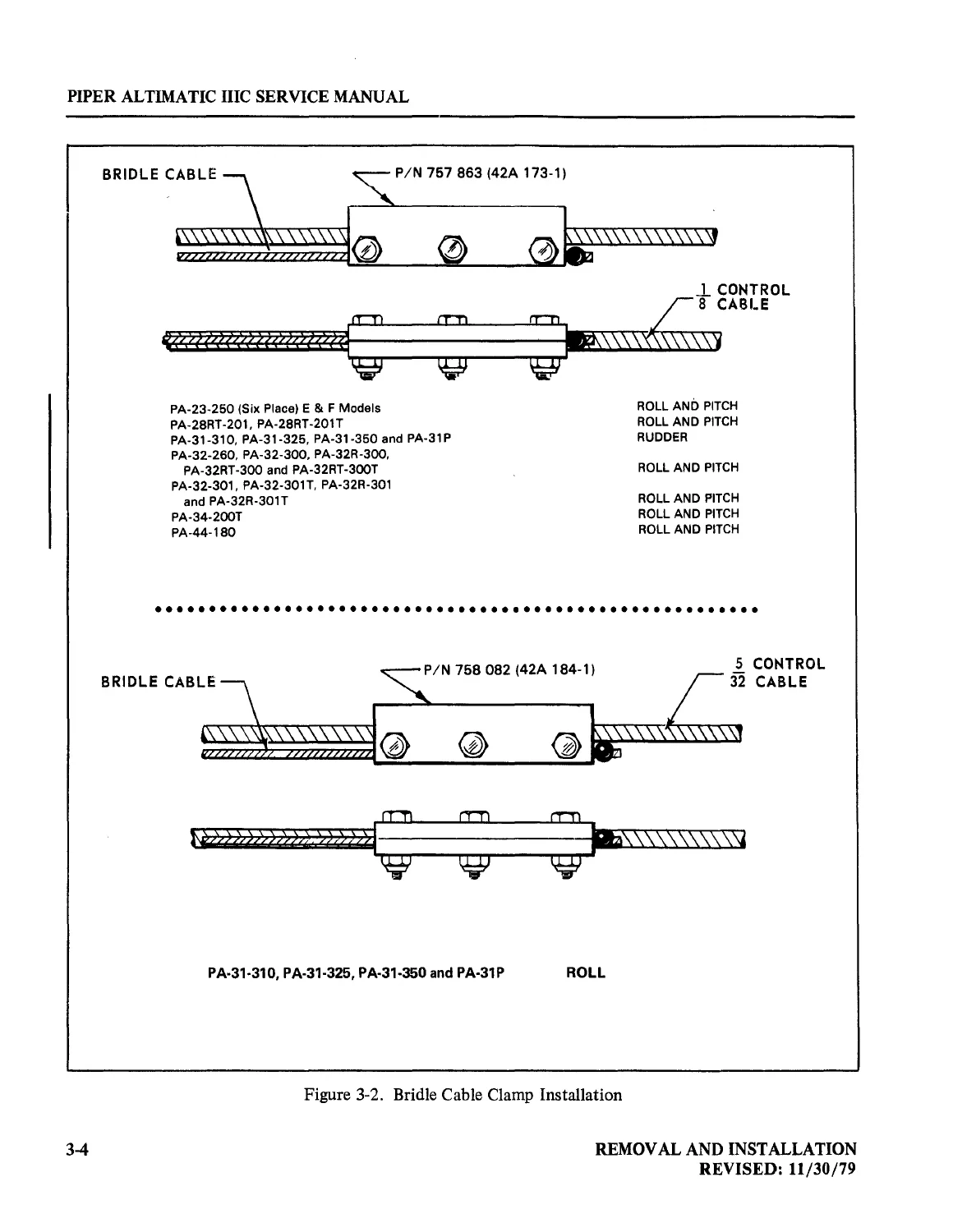
  • Section III: Removal and Installation (All components by aircraft model)
  • Section IV: Test Equipment (66D141 Test Kit)
  • Section V: Set-Up Procedures (Bench, Ground, and Flight Adjustments)
  • Section VI: Wiring Diagrams (System harnesses and block diagrams)

IMAGES PREVIEW

Piper AltiMatic IIIC Autopilot Service Manual 761-602 (1974-1981) PDF — PDF page 1 preview
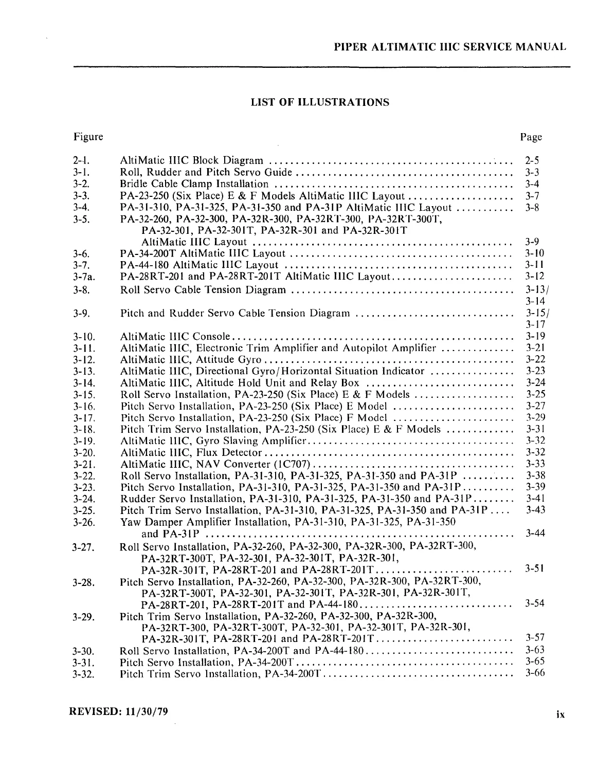
Piper AltiMatic IIIC Autopilot Service Manual 761-602 (1974-1981) PDF — PDF page 8 preview
Piper AltiMatic IIIC Autopilot Service Manual 761-602 (1974-1981) PDF — PDF page 30 preview

Part II: Glide Slope Coupler

  • Section VII: Description
  • Section VIII: Theory of Operation
  • Section IX: Removal and Installation
  • Section X: Test Equipment
  • Section XI: Bench Set-Up Procedures
  • Section XII: Ground Check and Flight Set-Up Procedures

Part III: Electronic Pitch Trim

  • Section XIII: Introduction and Description
  • Section XIV: Theory of Operation
  • Section XV: Ground Check – Electronic Pitch Trim System
  • Section XVI: Troubleshooting

This manual also includes detailed wiring diagrams, schematic diagrams (servo, relay box, altitude hold unit, electronic trim system), and multiple setup and adjustment procedures for the autopilot amplifier and trim system.

Whether you are an A&P mechanic, an avionics technician, or a dedicated owner-operator, this official Piper service manual provides the detailed procedures needed to maintain, troubleshoot, and repair the AltiMatic IIIC autopilot system. It covers everything from servo cable tension adjustments and console set-up to full system bench checks and flight tuning for specific Piper aircraft models including the PA-23, PA-31, PA-32, PA-34, and PA-44.

Complete PDF Bookmark Tree

Complete Bookmarks

The complete bookmarks in the “Piper AltiMatic IIIC Autopilot Service Manual 761-602 (1974-1981) PDF” are as follows:

SERVICE MANUAL (P/N 761 602)p. 1
REVISIONS ISSUEDp. 3
FOREWORDp. 4
TABLE OF CONTENTSp. 6
LIST OF ILLUSTRATIONSp. 8
PART I – ALTIMATIC IIICp. 12
SECTION I – INTRODUCTION AND DESCRIPTIONp. 13
Introductionp. 14
Descriptionp. 14
SECTION II – THEORY OF OPERATIONp. 15
Piper AltiMatic IIIC Automatic Flight Control Systemp. 16
Consolep. 16
Amplifierp. 16
Gyrosp. 16
Horizontal Situation Indicator (Non-Slaved) (Optional)p. 17
Horizontal Situation Indicator (Slaved) (Optional)p. 17
Yaw Damper System (Optional)p. 18
Roll, Yaw (Optional), and Pitch Servosp. 18
Pitch Trim Servop. 18
Altitude Controllerp. 18
Modes of Operationp. 18
Roll Modep. 18
Heading Modep. 18
Pitch Modep. 19
Altitude Hold Modep. 19
Lateral Guidance System (Radio Coupler)p. 19
Omni Modep. 19
Nav Modep. 19
Heading Modep. 19
Localizer (Normal) Modep. 19
Localizer (Reverse) Modep. 19
SECTION III – REMOVAL AND INSTALLATIONp. 21
Introductionp. 27
Pre-Installation Check and Adjustments of Roll, Yaw and Pitch Servo Assembliesp. 27
Console (AltiMatic IIIC)p. 44
Removal of Console (PA-23-250 Six Place) E & F Modelsp. 44
Installation of Console (PA-23-250 Six Place) E & F Modelsp. 44
Removal of Autopilot Amplifier (PA-23-250 Six Place) E & F Modelsp. 45
Removal of Electronic Trim Amplifier (PA-23-250 Six Place) E & F Modelsp. 45
Installation of Electronic Trim Amplifier (PA-23-250 Six Place) E & F Modelsp. 45
Installation of Autopilot Amplifier (PA-23-250 Six Place) E & F Modelsp. 45
Removal of Attitude Gyro (PA-23-250 Six Place) E & F Modelsp. 45
Installation of Attitude Gyro (PA-23-250 Six Place) E & F Modelsp. 46
Removal of Directional Gyro and/ or Horizontal Situation Indicator (PA-23-250 Six Place) E & F Modelsp. 47
Installation of Directional Gyro and / or Horizontal Situation Indicator (PA-23-250 Six Place) E & F Modelsp. 48
Removal of Altitude Hold Unit (PA-23-250 Six Place) E & F Modelsp. 48
Installation of Altitude Hold Unit (PA-23-250 Six Place) E & F Modelsp. 49
Removal of Relay Box (PA-23-250 Six Place) E & F Modelsp. 49
Installation of Relay Box (PA-23-250 Six Place) E & F Modelsp. 49
Removal of Roll Servo (PA-23-250 Six Place) E & F Modelsp. 50
Installation of Roll Servo (PA-23-250 Six Place) E & F Modelsp. 50
Removal of Pitch Servo (PA-23-250 Six Place) E & F Modelsp. 51
Installation of Pitch Servo (PA-23-250 Six Place) E Modelp. 51
Installation of Pitch Servo (PA-23-250 Six Place) F Modelp. 53
Removal of Pitch Trim Servo (PA-23-250 Six Place) E & F Modelsp. 55
Installation of Pitch Trim Servo (PA-23-250 Six Place) E & F Modelsp. 55
Removal of Gyro Slaving Amplifier (PA-23-250 Six Place) E & F Modelsp. 56
Installation of Gyro Slaving Amplifier (PA-23-250 Six Place) E & F Modelsp. 56
Removal of Flux Detector (PA-23-250 Six Place) E & F Modelsp. 56
Installation of Flux Detector (PA-23-250 Six Place) E & F Modelsp. 58
Removal of NAV Converter (IC707) (PA-23-250 Six Place) E & F Modelsp. 58
Installation of NAV Converter (lC707) (PA-23-250 Six Place) E & F Modelsp. 58
Removal of Console (PA-31-31O, PA-31-325, PA-31-350 and PA-31P)p. 59
Installation of Console (PA-31-31O, PA-31-325, PA-31-350 and PA-31P)p. 59
Removal of Autopilot Amplifier (PA-31-31O, PA-31-325, PA-31-350 and PA-31P)p. 59
Removal of Electronic Trim Amplifier (PA-31-310, PA-31-325, PA-31-350 and PA-31P)p. 59
Installation of Electronic Trim Amplifier (PA-31-31O, PA-31-325, PA-31-350and PA-31P)p. 59
Installation of Autopilot Amplifier (PA-31-31O, PA-31-325, PA-31-350 and PA-31P)p. 60
Removal of Attitude Gyro (PA-31-31O, PA-31-325, PA-31-350 and PA-3IP)p. 60
Installation of Attitude Gyro (PA-31-31O, PA-31-325, PA-31-350 and P A-31 P)p. 60
Removal of Directional Gyro and/or Horizontal Situation Indicator (PA-31-310,PA-31-325, PA-31-350 and PA-31P)p. 61
-Installation of Directional Gyro and / or Horizontal Situation Indicator (PA-31-310, PA-31-325, PA-31-350 and PA-31P)p. 61
Removal of Altitude Hold Unit (PA-31-31O, PA-31-325, PA-31-350 and PA-31 P)p. 61
Installation of Altitude Hold Unit (PA-31-31O, PA-31-325, PA-31-350 and PA-31P)p. 62
Removal of Relay Box (PA-31-31O, PA-31-325, PA-31-350 and PA-31P)p. 62
Installation of Relay Box (PA-31-31O, PA-31-325, PA-31-350 and PA-31P)p. 62
Removal of Roll Servo (PA-31-31O, PA-31-325, PA-31-350 and PA-31P)p. 62
Installation of Roll Servo (PA-31-31O, PA-31-325, PA-31-350 and PA-31P)p. 62
Removal of Pitch Servo (PA-31-31O, PA-31-325, PA-31-350 and PA-31P)p. 64
Installation of Pitch Servo (PA-31-310, PA-31-325, PA-31-350 and PA-3IPp. 65
Removal of Rudder Servo (PA-31-31O, PA-31-325, PA-31-350 and PA-31Pp. 65
Installation of Rudder Servo (PA-31-31O, PA-31-325, PA-31-350and PA-31 P)p. 66
Removal of Pitch Trim Servo (PA-31-310, PA-31-325, PA-31-350 and PA-31Pp. 67
Installation of Pitch Trim Servo (PA-31-31O, PA-31-325, PA-31-350 and PA-31P)p. 67
Removal of Yaw Damper Amplifier (PA-31-31O, PA-31-325, PA-31-350 and PA-31 P)p. 68
Installation of Yaw Damper Amplifier (PA-31-31O, PA-31-325, PA-31-350 and PA-31 P)p. 68
Removal of Gyro Slaving Amplifier (PA-31-31O, PA-31-325, PA-31-350 and PA-31 P)p. 69
Installation of Gyro Slaving Amplifier (PA-31-31O, PA-31-325, PA-31-350 and PA-31 P)p. 69
Removal of Flux Detector (PA-31-31O, PA-31-325, PA-31-350 and PA-31P)p. 70
Installation of Flux Detector (PA-31-31O, P A-31-325, P A-31-350 and P A-31 P)p. 70
Removal of NAV Converter (lC707) (PA-31-310, PA-31-325, PA-31-350 and P A-31 P)p. 70
Installation of NAV Converter (IC707) (PA-31-31O, PA-31-325, PA-31-350 and PA-31Pp. 70
Removal of Console (PA-32-260, PA-32-300, PA-32R-300, PA-32RT-300PA-32RT-300T, PA-32-301, PA-32-301T, PA-32R-301 and PA-32R-301T)p. 70
Installation of Console (PA-32-260, PA-32-300, PA-32R-300, PA-32RT-300,PA-32RT-300T, PA-32-301, PA-32-301T, PA-32R-301 and PA-32R-301T)p. 70
Removal of Autopilot Amplifier (PA-32-260, SIN 32-750001 to 7700023; PA-32-300, SIN 32-7540001 to 7840045 and PA-32R-300,SIN 32R-7680001 to 77804)p. 70
Removal of Electronic Trim Amplifier (PA-32-260,SIN 32-7500001 to 7700023 and PA-32-300, SIN 32-7540001 to 7840045)p. 71
Installation of Electronic Trim Amplifier (PA-32-260,SIN 32-7500001 to 7700023 and PA-32-300, SIN 32-7540001 to 7840045)p. 71
Installation of Autopilot Amplifier (PA-32-260, SIN 32-7500001 to7700023; PA-32-300, SIN 32-7540001 to 7840045 and PA-32R-300,SIN 32R-7680001 to 77804)p. 71
Removal of Autopilot Amplifier (PA-32-260, SIN 32-7800001and up; PA-32-300, SIN 32-7840046 anq up; PA-32R-300,SIN 32R-7780418 and up; PA-32RT-300, PA-32RT-300T, PA-32-301,PA-32-30IT, PA-32R-301 and PA-32R-301T)p. 71
Installation of Autopilot Amplifier (PA-32-260,SIN 32-7800001 and up; PA-32-300, SIN 32-7840046 and up;PA-32R-300, SIN 32R-7780418 and up; PA-32RT-300, PA-32RT-300T,PA-32-301, PA-32-301T, PA-32R-301 and PA-32R-301T)p. 72
Removal of Electronic Trim Amplifier (PA-32-260,SIN 32-7800001 and up; PA-32-300, SIN 32-7840046 and up;PA-32R-300, PA-32RT-300, PA-32RT-300T, PA-32-301, PA-32-301T,PA-32R-301 and PA-32R-301T)p. 72
Installation of Electronic Trim Amplifier (PA-32-260,SIN 32-78-00001 and up; PA-32-300, SIN 32-7840046 and up; PA-32R-300,PA-32RT-300, PA-32RT-300T, PA-32-301, PA-32-301T, PA-32R-301and PA-32R-301T)p. 72
Removal of Attitude Gyro (PA-32-260, PA-32-300, P A-32R-300,PA-32RT-300, PA-32RT-300T, PA-32-301, PA-32-301T, PA-32R-301 and PA-32R-301T)p. 72
Installation of Attitude Gyro (PA-32-260, PA-32-300, PA-32R-300,PA-32RT-300, PA-32RT-300T, PA-32-301, PA-32-301T,PA-32R-301 and PA-32R-301T)p. 72
Removal of Directional Gyro and/or Horizontal Situation Indicator (PA-32-260, PA-32-300, PA-32R-300,PA-32RT-300, PA-32RT-300T, PA-32-301, PA-32-301T, PA-32R-301 and PA-32R-301T)p. 73
Installation of Directional Gyro and/or Horizontal Situation Indicator (P A-32-260, P A-32-300, P A-32R-300,PA-32RT-300, PA-32RT-300T, PA-32-301, PA-32-301T, PA-32R-301and PA-32R-301T)p. 73
Removal of Altitude Hold Unit (PA-32-260, PA-32-300, PA-32R-300,PA-32RT-300, PA-32RT-300T, PA-32-301, PA-32-301T, PA-32R-301 and PA-32R-301T)p. 73
Installation of Altitude Hold Unit (PA-32-260, PA-32-300,PA-32R-300, PA-32RT-300, PA-32RT-300T, PA-32-301, PA-32-301T,PA-32R-30 I and PA-32R-30 1T)p. 73
Removal of Relay Box (P A-32-260, SIN 32-7500001 to 7700023;PA-32-300, SIN 32-7540001 to 7840045 and PA-32R-300,SIN 32R-7680001 to 7780417)p. 73
Installation of Relay Box (P A-32-260, SIN 32-7500001 to 7700023; PA-32-300, SIN 32-754000 I to 7840045 andPA-32R-300, SIN 32R-7680001 to 7780417)p. 74
Removal of Relay Box (P A-32-260, SIN 32-7800001 and up;PA-32-300, SIN 32-7840046 and up; PA-32R-300, SIN 32R-7780418 and up; PA-32RT-300, PA-32RT-300T, PA-32-301, PA-32-301T,PA-32R-301 and PA-32R-301T)p. 74
Installation of Relay Box (PA-32-260, SIN 32-7800001 and up;PA-32-300, SIN 32-7840046 and up; PA-32R-300, SIN 32R-7780418 and up; PA-32RT-300, PA-32RT-300T, PA-32-301, PA-32-301T,PA-32R-301 and PA-32R-301T)p. 74
Removal of Roll Servo (PA-32-260, PA-32-300, PA-32R-300, PA-32RT-300,PA-32RT-300T, PA-32-301, PA-32-301T, PA-32R-301 and PA-32R-301T)p. 74
Installation of Roll Servo (PA-32-260, P A-32-300, P A-32R-300,PA-32-RT-300, PA-32RT-300T, PA-32-301, PA-32-301T, PA-32R-301 and PA-32R-301T)p. 74
Removal of Pitch Servo (PA-32-260 and PA-32-300,SIN 32-7540001 to 7840222)p. 77
Removal of Pitch Servo (PA-32-300, SIN 32-7940001 and up;PA-32R-300, PA-32RT-300, PA-32RT-300T, PA-32-301, PA-32-301T,PA-32R-301 and PA;.32R-301T)p. 77
Installation of Pitch Servo (PA-32-260 and PA-32-300,SIN 32-7540001 to 7840222)p. 77
Installation of Pitch Servo (PA-32-300, SIN 32-7940001and up; PA-32R-300, PA-32RT-300, PA-32RT-300T, PA-32-30I,PA-32-301T, PA-32R-301 and PA-32R-301T)p. 78
Removal of Pitch Trim Servo (PA-32-260, PA-32-300, PA-32R-300,PA-32RT-300, PA-32RT-300T, PA-32-301, PA-32-301T, PA-32R-301and P A-32R-301T)p. 80
Installation of Pitch Trim Servo (PA-32-260, PA-32-300,PA-32R-300, PA-32RT -300, PA-32RT -300T, PA-32-30 1, PA-32-301T PA-32R-301 and PA-32R-301T)p. 80
Removal of Console (PA-34-200T)p. 82
Installation of Console (PA-34-200T).p. 82
Removal of Autopilot Amplifier (PA-34-200T)p. 82
Installation of Autopilot Amplifier (PA-34-200T)p. 84
Removal of Electronic Trim Amplifier (PA-34-200T)p. 84
Installation of Electronic Trim Amplifier (PA-34-200T)p. 84
Removal of Attitude Gyro (PA-34-200T)p. 84
Installation of Attitude Gyro (PA-34-200T)p. 84
Removal of Directional Gyro and/or Horizontal Situation Indicator (PA-34-200T)p. 84
Installation of Directional Gyro andlor Horizontal Situation Indicator (PA-34-200T)p. 85
Removal of Altitude Hold Unit (PA-34-200T, Serial Nos. 34-7570001 to34-7770185 incl., 34-7770187 to 34-7770263 incl.)p. 85
Installation of Altitude Hold Unit (PA-34-200T, Serial Nos. 34-7570001 to 34-7770185 inc!., 34-7770187 to 34-7770263 inc!.)p. 85
Removal of Altitude Hold Unit (PA-34-200T, Serial Nos. 34-7770186,34-7770264 and up)p. 85
Installation of Altitude Hold Unit (PA-34-200T, Serial Nos. 34-7770186,34-7770264 and up)p. 85
Removal of Relay Box (PA-34-200T)p. 86
Installation of Relay Box (PA-34-200T)p. 86
Removal of Roll Servo (PA-34-200T)p. 86
Installation of Roll Servo (PA-34-200T)p. 88
Removal of Pitch Servo (PA-34-200T)p. 89
Installation of Pitch Servo (PA-34-200T)p. 89
Removal of Pitch Trim Servo (PA-34-200T)p. 90
Installation of Pitch Trim Servo (PA-34-200T)p. 91
Removal of Gyro Slaving Amplifier (PA-34-200T)p. 92
Installation of Gyro Slaving Amplifier (PA-34-200T)p. 92
Removal of Flux Detector (PA-34-200T)p. 92
Installation of Flux Detector (PA-34-200T)p. 92
Removal of Console (PA-44-180)p. 93
Installation of Console (PA-44-180)p. 93
Removal of Autopilot Amplifier (P A-44-180)p. 93
Installation of Autopilot Amplifier (PA-44-180)p. 93
Removal of Electronic Trim Amplifier (PA-44-180)p. 93
Installation of Electronic Trim Amplifier (PA-44-ISO)p. 93
Removal of Attitude Gyro (PA-44-ISO)p. 94
Installation of Attitude Gyro (PA-44-180)p. 94
Removal of Directional Gyro and/or Horizontal Situation Indicatorp. 94
Installation of Directional Gyro and/or Horizontal Situation Indicator (PA-44-180)p. 94
Removal of Altitude Hold Unit (PA-44-180)p. 94
Installation of Altitude Hold Unit (PA-44-180)p. 95
Removal of Re\ay Box (PA-44-180)p. 95
Installation of Relay Box (PA-44-180)p. 95
Removal of Roll Servo (P A-44-180)p. 96
Installation of Roll Servo (PA-44-180)p. 96
Removal of Pitch Servo (PA-44-180)p. 97
Installation of Pitch Servo (PA-44-180)p. 97
Removal of Pitch Trim Servo (PA-44-180)p. 98
Installation of Pitch Trim Servo (PA-44-180)p. 99
Removal of Console (PA-28RT-201 and PA-28RT-201T)p. 99
Installation of Console (PA-28RT-201 and PA-28RT-201T)p. 99
Removal of Autopilot Amplifier (PA-28RT-201 and PA-28RT-201T)p. 99
Removal of Electronic Trim Amplifier (PA-28RT-201 and PA-28RT-201T)p. 100
Installation of Electronic Trim Amplifier (PA-28RT -201 and PA-2SRT-201T)p. 100
Installation of Autopilot Amplifier (P A-28 R T -201 and PA-28RT-201T)p. 100
Removal of Attitude Gyro (PA-28RT-201 and PA-28RT-201T)p. 100
Installation of Attitude Gyro (PA-28RT-201 and PA-28RT-201 T)p. 100
Removal of Directional Gyro and/ or Horizontal Situation Indicator (PA-28RT-201 and PA-28RT-201T)p. 100
Installation of Directional Gyro and/ or Horizontal Situation Indicator (PA-28RT-201 and PA-28RT-201T)p. 101
Removal of Altitude Hold Unit (PA-28RT-201 andPA-28RT-201T) )p. 101
Installation of Altitude Hold Unit (PA-28RT-201 and PA-28RT-20IT)p. 101
Removal of Relay Box (PA-28RT-201 and PA-28RT-201T)p. 101
Installation of Relay Box (PA-28RT-201 and PA-28RT-201T)p. 101
Removal of Roll Servo (PA-28RT-201 and PA-28RT-201T)p. 101
Installation of Roll Servo (PA-28RT-201 and PA-28RT-201T)p. 102
Removal of Pitch Servo (PA-28RT-201 and PA-28RT-201T)p. 102
Installation of Pitch Servo (PA-28RT-201 and PA-28RT-201T)p. 102
Removal of Pitch Trim Servo (PA-28RT-201 and PA-28RT-201T)p. 103
Installation of Pitch Trim Servo (PA-28RT-201 and PA-28RT-201T)p. 104
Removal of Nav Flag Adapter (PA-23-250 Six Place,SIN 27-7554001, 7554074 to 7754127; PA-31, SIN 31-7512023 to 7712064; PA-31-350, SIN 31-7552054 to 7752100,31-7752102 to 7752113 and PA-31P, SIN 31P-7630014 to 7730012)p. 104
Installation of Nav Flag Adapter (PA-23-250 Six Place,SIN 27-7554001, 7554074 to 7754127; PA-31, SIN 31-7512023 to 7712064; PA-31-350, SIN 31-7552054 to 7752100,31-7752102 to 7752113 and PA-31P, SIN 31P-7630014 to 7730012)p. 104
Removal of Nav Flag Adaptcr (PA-32-260, SIN 32-7600001to 7700017; PA-32-300, SIN 32-7640001 to 7740075; PA-32R-300,SIN 32R-7680001 to 7780350 and PA-34-200T, SIN 34-7670001 to 777(261)p. 104
Installation of Nav Flag Adapter (PA-32-260, SIN 32-760001 to 7700017; PA-32-300, SIN 32-7640001 to 7740075; PA-32R-300,SIN 32R-7680001 to 7780350 and P A-34-200T, SIN 34-7670001 to 7770261)p. 105
Removal of KA-52 Autopilot Adapterp. 105
Installation of KA-52 Autopilot Adapterp. 106
SECTION IV – TEST EQUIPMENTp. 107
Introduction – Test Equipment Requirements. AutoPilot Test Kit,Piper PIN 753 439 (66D141)p. 108
66D141-1 Gyro Substitutep. 108
66D141-2 Power Sectionp. 108
66D141-3 Console Substitutep. 109
66D141-4 Radio Coupler Testerp. 111
66Dl41 Test Kit and Cablesp. 111
Troubleshootingp. 111
Checking Servo Motor Current Drain (No Load)p. 113
SECTION V – SET-UP PROCEDURESp. 115
Introductionp. 116
Bench Set-Up and Adjustment of AltiMatic IIIC Console and 1C515-1/C515-3 Amplifier Without Radio Couplerp. 116
Roll Threshold Adjustment for AltiMatic IIICp. 121
Pitch Bench Set-Up for AltiMatic IIICp. 123
Pitch Threshold Adjustment for AltiMatic IIICp. 125
AltiMatic lIIC Ground Check Without Radio Coupler (Roll)p. 127
AltiMatic IIIC Flight Adjustments Without Radio Coupler (Roll)p. 127
Bench Set-Up and Adjustments for AltiMatic IIIC Console and 1C515-1/1C515-3 Amplifier With Radio Couplerp. 129
Roll Threshold Adjustment for AltiMatic IIICp. 136
Pitch Bench Set-Up for AltiMatic IIICp. 138
Pitch Threshold Adjustment for AltiMatic IIICp. 139
AltiMatic IIIC Ground Checks With Radio Coupler (Roll)p. 140
Ground Check – Pitchp. 141
AltiMatic IIIC Flight Adjustments With Radio Coupler (Roll)p. 143
AltiMatic IIIC Flight Adjustment – Pitchp. 146
AltiMatic IIIC Ground Check (Optional Yaw Damper)p. 147
Check and Adjusting Radio Gainp. 147
Piper Omni/Localizer Coupler Modification (1 C388 Series)p. 149
NAV Converter (1C707) Alignment Procedurep. 152
Adjustments of Slaving Sub-Systemp. 154
AltiMatic IIIC With Optional King KCS-55 Compass System Alignment Procedurep. 156
Yaw Damper Ground Checkp. 159
SECTION VI – WIRING DIAGRAMSp. 162
Introductionp. 163
PART II – GLIDE SLOPE COUPLERp. 198
SECTION VII – DESCRIPTIONp. 199
Descriptionp. 200
SECTION VIII – THEORY OF OPERATIONp. 201
Theory of Operationp. 202
Couplingp. 203
SECTION IX – REMOVAL AND INSTALLATIONp. 206
Introductionp. 207
Removal of Glide Slope Coupler (PA-23-250 Six Place) E & F Modelsp. 207
Installation of Glide Slope Coupler (PA-23-250 Six Place) E & F Modelsp. 207
Removal of Glide Slope Coupler (PA-31-31O, PA-31-325, PA-31-350 and PA-31P)p. 207
Installation of Glide Slope Coupler (PA-31-310, PA-31-325, PA-31-350 and PA-31P)p. 207
Removal of Glide Slope Coupler (PA-32-260, S/N 32-7500001 to 7700023 and PA-32-300, S/N 32-7540001 to 7840045)p. 208
Installation of Glide Slope Coupler (PA-32-260, S/N 32-7500001 to 7700023 and PA-32-300, S/N 32-7540001 to 7840045)p. 208
Removal of Glide Slope Coupler (PA-32-260, S/N 32-7800001 and up; PA-32-300, S/N 32-7840046 and up; PA-32R-300, PA-32RT-300, PA-32RT-300T, PA-32-301, PA-32-301T, PA-32R-301, PA-32R-301T and P A-34-200T)p. 208
Installation of Glide Slope Coupler (PA-32-260, S/N 32-7800001 and up;PA-32-300, S/N 32-7840046 and up; PA-32R-300, PA-32RT-300, PA-32RT-300TPA-32-301, PA-32-301T, PA-32R-301, PA-32R-301T and PA-34-200T)p. 208
Removal of Glide Slope Coupler (PA-44-180)p. 209
Installation of Glide Slope Coupler (PA-44-180)p. 209
Removal of Glide Slope Coupler (PA-28RT-201 and PA-28RT-201T)p. 209
Installation of Glide Slope Coupler (PA-28RT-201 and PA-28RT-201T)p. 209
SECTION X – TEST EQUIPMENTp. 215
Test Equipment Requirementsp. 216
66D141-4 Radio Coupler Testerp. 216
Glide Slope Cablesp. 216
Troubleshootingp. 216
SECTION XI – BENCH SET-UP PROCEDURESp. 219
Introductionp. 220
Equipment Required for Bench Checkp. 220
Bench Checking of the Glide Slope Couplerp. 220
Wiring Diagramsp. 223
SECTI'ON XII – GROUND CHECK AND FLIGHT SET-UP PROCEDURESp. 226
Ground Operational Checkp. 227
Flight Set-Up Proceduresp. 227
PART III – ALTIMATIC IIIC , ELECTRONIC PITCH TRIMp. 229
SECTION XIII – INTRODUCTION AND DESCRIPTIONp. 230
Introductionp. 231
Descriptionp. 231
SECTION XIV – THEORY OF OPERATIONp. 232
System Explanationp. 233
SECTION XV – GROUND CHECK – ELECTRONIC PITCH TRIM SYSTEMp. 234
Ground Check – Electronic Pitch Trim Systemp. 235
SECTION XVI – TROUBLESHOOTINGp. 238
Introduction & Isolation Block Diagramp. 239

Key Capabilities & Repairs Supported:

  • Complete system troubleshooting using the 66D141 test kit and isolation block diagrams.
  • Step-by-step removal and installation of the console, amplifier, gyros, servos, and trim units for multiple aircraft models.
  • Bench set-up, threshold adjustments, and ground checks for the autopilot and radio coupler.
  • In-flight adjustment procedures for roll, pitch, heading, and altitude hold modes.
  • Detailed set-up and alignment of the slaved horizontal situation indicator (HSI) and flux detector.
  • Servicing and adjustment of the yaw damper system and electronic pitch trim.
  • Full wiring diagrams, harness schematics, and connector pinouts.

This is the exact factory-authorized information required to correctly diagnose and repair the Piper AltiMatic IIIC autopilot. Having the correct specifications, torque values, and test procedures is essential for safe and reliable flight control system operation.

Instant PDF Delivery: This is a digital download. No physical product will be shipped. You will receive the complete PDF immediately after purchase, viewable on any device—computer, tablet, or smartphone. Print the entire manual or select pages for use in your hangar or workshop.

Reviews

There are no reviews yet.

Be the first to review “Piper AltiMatic IIIC Autopilot Service Manual 761-602 (1974-1981) PDF”

What Our Customers Say

★★★★★ Live reviews from customers
Loading customer reviews...
0
    0
    Your Cart
    Your cart is emptyReturn to Shop
    🛒
    Recently Purchased
    🕒 verified order