
Airbus A350-900 & A350-1000 Aircraft Characteristics Airport and Maintenance Planning Manual (AC) – Revision 10
Original price was: $44.95.$24.95Current price is: $24.95.
The Airbus A350 Aircraft Characteristics – Airport and Maintenance Planning (AC) manual, Revision 10 (Jul 01/21), covering A350-900 and A350-1000 airport planning, ground handling, pavement data, ground clearances, jacking, servicing and rescue/fire fighting data in a single PDF.
Description
Airbus A350-900 & A350-1000 Aircraft Characteristics Airport and Maintenance Planning Manual (AC) – Revision 10
The Airbus A350 Aircraft Characteristics – Airport and Maintenance Planning (AC) manual is the reference document used by airport operators, airlines, ground handlers, MRO planners and civil engineers to plan everything around the A350-900 and A350-1000 while the aircraft is on the ground. This Revision 10 issue (dated Jul 01/21) is published by Airbus S.A.S. and is written for the whole A350 XWB family, with aircraft-specific data separated by the ON A/C A350-900 and ON A/C A350-1000 markers throughout the document. If you are preparing a stand layout, sizing a hangar door, checking a runway PCN, planning a jacking operation or briefing a fire crew, the answer sits inside this A350 Aircraft Characteristics Airport and Maintenance Planning manual.
File Details
- Manual type: Aircraft Characteristics – Airport and Maintenance Planning (AC)
- Brand / Publisher: Airbus S.A.S.
- Models covered: A350-900 and A350-1000 (A350 XWB family)
- Language: English
- Page count: 411 pages
- File format: PDF
- Revision: No. 10
- Revision date: Jul 01/21
Chapters Covered
- Chapter 1 – Introduction and Glossary
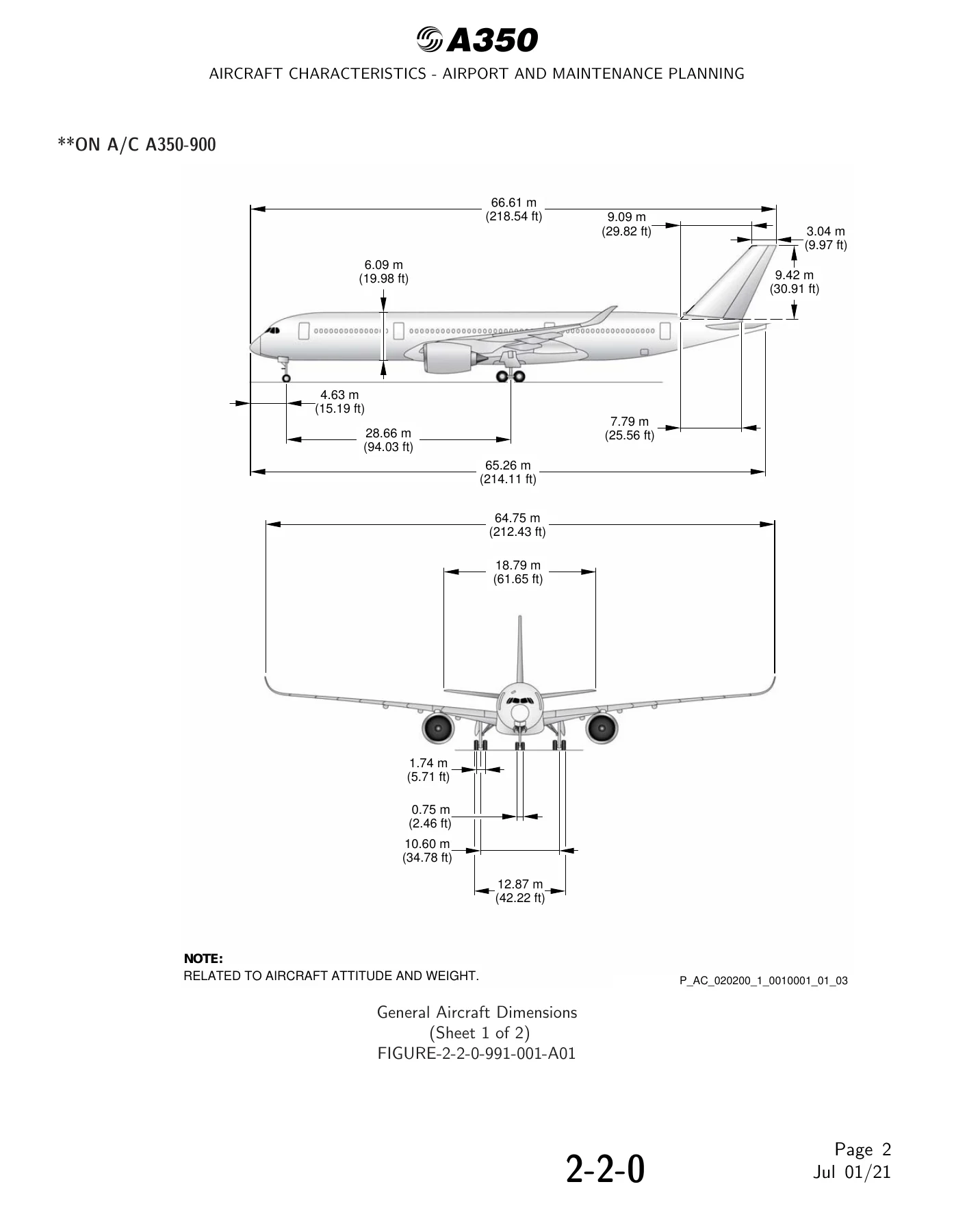
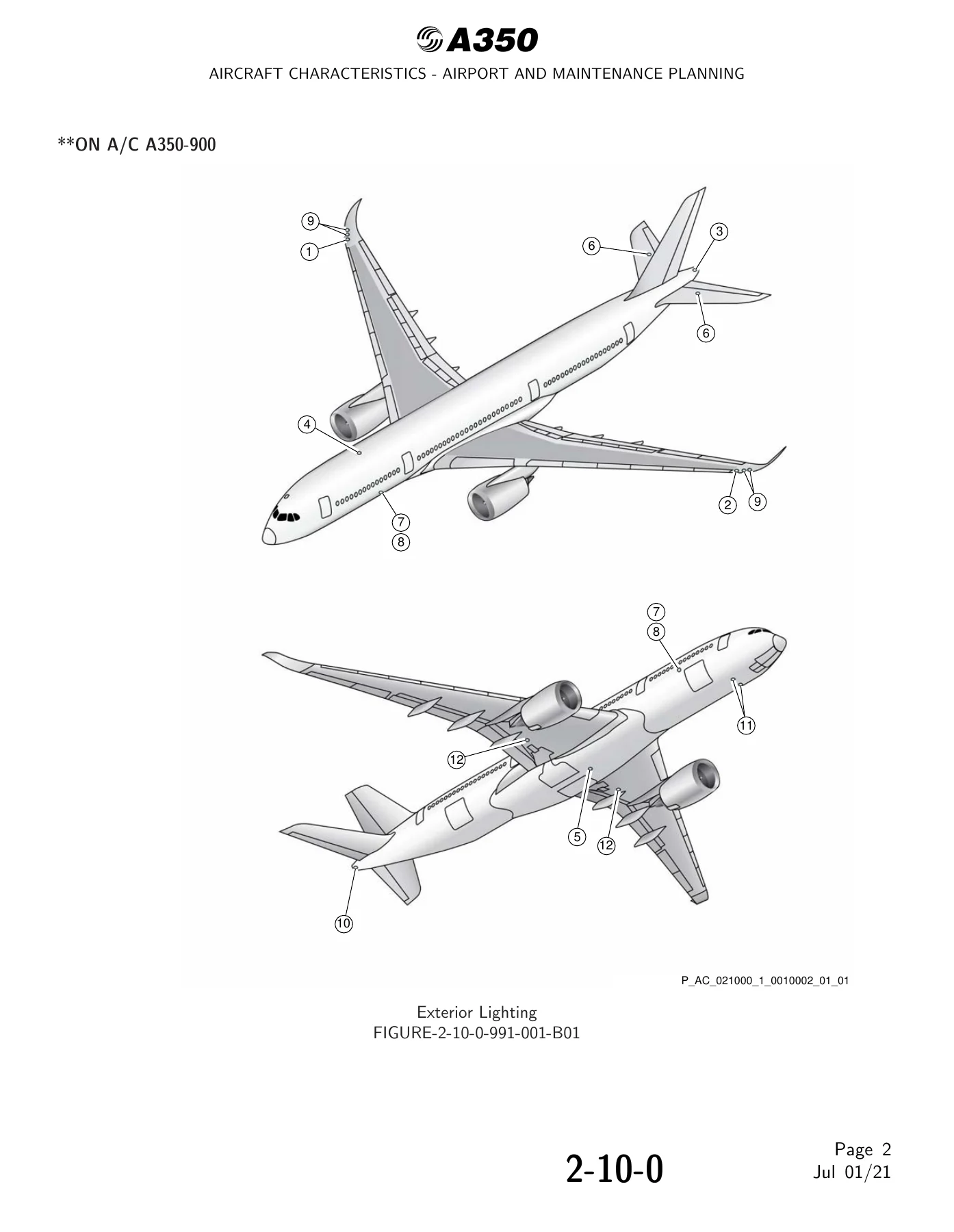
- Chapter 2 – Aircraft Description: General Aircraft Characteristics Data; General Aircraft Dimensions; Ground Clearances; Interior Arrangements – Plan View; Interior Arrangements – Cross Section; Cargo Compartments; Door Clearances and Location; Escape Slides; Landing Gear; Landing Gear Maintenance Pits; Exterior Lighting; Antennas and Probes Location; Engine and Nacelle; Auxiliary Power Unit; Leveling, Symmetry and Alignment; Jacking for Maintenance; Jacking of the Landing Gear
- Chapter 3 – Aircraft Performance: General Information; Payload/Range – ISA Conditions; Take-Off Weight Limitation; Aerodrome Reference Code; Landing Field Length; Final Approach Speed
- Chapter 4 – Ground Maneuvering: General Information; Turning Radii; Minimum Turning Radii; Visibility from Cockpit in Static Position; Runway and Taxiway Turn Paths (135 and 90 degree runway-to-taxiway, 180 degree turn on a runway, 135 and 90 degree taxiway-to-taxiway); Runway Holding Bay; Minimum Line-Up Distance Corrections; Aircraft Mooring
- Chapter 5 – Terminal Servicing: Aircraft Servicing Arrangements; Typical Ramp Layout (Open Apron and Gate); Terminal Operations – Full Servicing Turn Round Time; Terminal Operations – Transit Turn Round Time; Ground Service Connections Layout; Grounding (Earthing) Points; Hydraulic Servicing; Electrical Servicing; Oxygen Servicing; Fuel Servicing; Pneumatic Servicing; Oil Servicing; Potable Water Servicing; Waste Water Servicing; Cargo Control Panels; Engine Starting Pneumatic Requirements; Ground Pneumatic Power Requirements; Preconditioned Airflow Requirements; Ground Towing Requirements; De-Icing and External Cleaning
- Chapter 6 – Operating Conditions: Engine Exhaust Velocities and Temperatures (Ground Idle, Breakaway and Max Take-Off power); Danger Areas of the Engines; APU Exhaust Velocities and Temperatures
- Chapter 7 – Pavement Data: General Information; Landing Gear Footprint; Maximum Pavement Loads; Landing Gear Loading on Pavement; Flexible Pavement Requirements (US Army Corps of Engineers Design Method and LCN Conversion); Rigid Pavement Requirements (Portland Cement Association Design Method and LCN Conversion); ACN/PCN Reporting System; ACR/PCR Reporting System
- Chapter 8 – Scaled Drawings
- Chapter 10 – Aircraft Rescue and Fire Fighting
What this Airbus A350 AC manual actually hands you is not theory. It is the raw dimensional, weight, clearance, turning, servicing and pavement data that a real airport has to design around. Chapter 2 alone gives you dimensioned three-view drawings, door sill and ground clearance tables for FWD CG and AFT CG at MRW and light weight, cargo compartment volumes for LD3 containers and 88 in / 96 in pallets, escape slide geometry and the landing gear jacking points at FR12, RIB9 and the FR98 safety stay. Chapter 4 does the same for movement – turning radii at every steering angle, minimum turning radii, the ETACS camera views, 90, 135 and 180 degree turn paths using oversteering, ETACS and cockpit-over-centerline methods, and the minimum line-up distance corrections on TODA and ASDA. Chapter 5 breaks down every ground service connection – grounding studs, hydraulic service panels, electrical receptacles, fuel couplings, overpressure protectors and NACA flame arrestors, pneumatic connectors, oil fills, potable water and waste panels, cargo control panels – with the aft-of-nose, lateral and mean-height coordinates for each. Chapter 7 covers the pavement side with landing gear footprints, maximum vertical and horizontal pavement loads at the tire-ground interface, and ACN/PCN and ACR/PCR tables per weight variant. Chapter 6 gives the danger areas of the engines at ground idle and max take-off, and Chapter 10 supplies the aircraft rescue and fire fighting data including wheel/brake overheat safety areas, composite material locations, structural break-in points, emergency evacuation device dimensions and battery locations.
Who Uses This A350 Aircraft Characteristics Airport and Maintenance Planning Manual
Airport planners use the A350-900 and A350-1000 aircraft dimensions chapter to size taxiways, aprons, holding bays and gates. Civil engineers use the pavement chapter to work out whether an existing runway or apron can take the A350 at a given weight. Ground handlers use the turn round time charts and servicing connection layouts to plan stand equipment. Line maintenance and MRO teams use the jacking, landing gear, maintenance pit and leveling data to prepare hangars and heavy maintenance stands. Rescue and fire fighting crews use the ARFF chapter to plan approach zones, wheel safety areas and break-in points. All of that comes from the same A350 AC Revision 10 PDF.
Technical Data You Can Pull From This Manual
The A350-900 weight variant tables list Maximum Taxi Weight, Maximum Ramp Weight, Maximum Take-Off Weight, Maximum Landing Weight and Maximum Zero Fuel Weight across WV000 through WV023, including the WV013 ULR variant. The A350-1000 tables do the same across WV000 through WV011. Fuel capacity is given as 138 000 L (36 456 USgal) for the A350-900 and 158 790 L (41 949 USgal) for the A350-1000, with the ULR at 165 000 L. Standard two-class seating is 315 (48 BC / 267 EC) for the A350-900 and 369 (54 BC / 315 EC) for the A350-1000. Final approach speed is stated at 140 kt for the A350-900 (Approach Category C) and 147 kt for the A350-1000 (Approach Category D). Hydraulic servicing pressure is 344.75 bar (5000 psi). Nose gear tires are 1 050x395R16 28PR, A350-900 main gear tires are 1 400x530R23 42PR and A350-1000 main gear tires are 50x20R22 34PR. Grounding points, refuel couplings, HP and LP pneumatic connectors and every ground service access door are listed with their distances aft of nose, off-centerline and height above ground.
Why the Airbus A350 AC Manual Matters
Get a clearance wrong and you either damage a composite wing, block a taxiway or overstress a pavement. The A350 AC manual replaces guesswork with published figures at defined weight and CG conditions – FWD CG, AFT CG, MRW, 140 000 kg, 160 000 kg and A/C on jacks with FDL at 6.50 m. The ACN/PCN and ACR/PCR chapters tell you the reporting format and how to interpolate the operating weight for a given PCN or PCR. The jacking chapter gives the eligible static loads per jacking point (for example 17 670 daNm forward fuselage and 79 488 daNm wing on the A350-900, and 16 911 daNm forward fuselage and 90 764 daNm wing on the A350-1000). The engine danger areas give you the numbers to keep people clear – up to 67 m (220 ft) aft of the exhaust nozzles at ground idle and up to 442 m (1 450 ft) for the Trent XWB-84 or 488 m (1 600 ft) for the Trent XWB-97 at max take-off. Nothing in this A350 Aircraft Characteristics Airport and Maintenance Planning manual is optional reading if you work around the aircraft.
Get Instant Access to the A350 AC Manual PDF
IMAGES PREVIEW
This Airbus A350-900 and A350-1000 Aircraft Characteristics Airport and Maintenance Planning manual (AC) Revision 10 is delivered as an instant-download PDF. There is no shipping, no waiting for a courier and no regional restriction on delivery. Once payment clears, the file is available straight away and can be opened on a laptop, tablet or phone at the desk, on the ramp or in the hangar. Print the pages you need – the turning path diagrams, the ground clearance tables, the ACN table, the ARFF figures – and keep them in the binder at the stand. Whether you are an airport planner sizing a new apron, a civil engineer checking ACR/PCR, a maintenance planner preparing a jacking job, or a ground handler laying out a gate, this A350-900 and A350-1000 Airport and Maintenance Planning manual gives you the A350 figures directly from the source.
Reviews
There are no reviews yet.