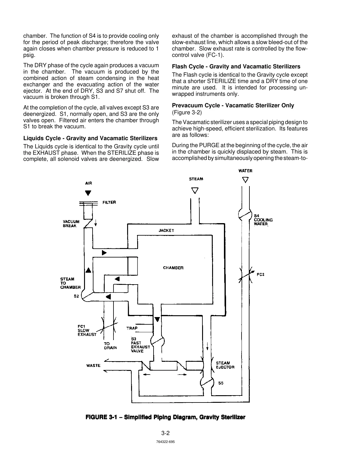
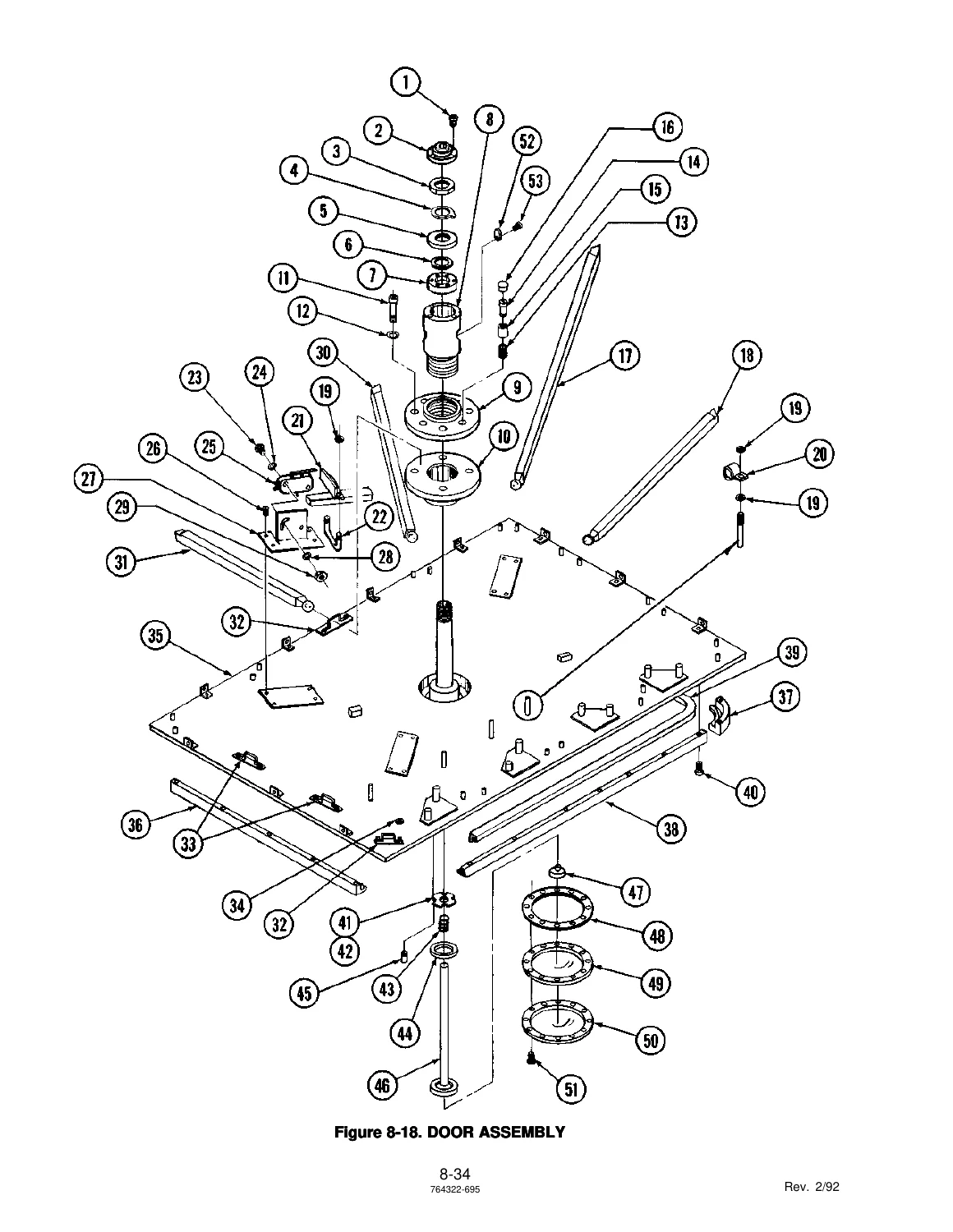
AMSCO Eagle 3000 Series Medium Sterilizers Maintenance Manual – Gravity & Vacamatic – P-764322-695
$39.95 Original price was: $39.95.$23.95Current price is: $23.95.
Complete maintenance manual for AMSCO Eagle 3000 Series Medium Sterilizers covering Gravity and Vacamatic units. Includes preventive maintenance, troubleshooting, component repair, field test procedures, exploded views, and parts lists. Document P-764322-695, Rev. 2/92.
Description
File Details
- Manual Type: Maintenance Manual
- Brand: AMSCO
- Model: Eagle 3000 Series Medium Sterilizers
- Coverage: Gravity and Vacamatic Sterilizers, Single Door and Double Door, Manual and Power Door
- Sizes: 24 x 36, 24 x 48, 24 x 60
- Document Number: P-764322-695
- Revision: Rev. 2/92
- Language: English
- Page Count: 254 pages
- File Format: PDF
Chapters Covered
- Section 1 β General Information
- Section 2 β Operating Instructions
- Component Identification/Function
- Sterilizer Cycles & Cycle Values
- Service Adjustments and Special Features
- Sterilizer Operation
- Section 3 β Principles of Operation
- Mechanical Operation
- Control System
- Cycle Descriptions
- Power Door
- Section 4 β Inspection and Maintenance
- Routine Inspection
- Preventive Maintenance
- Cleaning
- Preventive Maintenance Guide
- Section 5 β Field Test Procedure
- Test Instrumentation Required
- Installation Check
- Door Switch Adjustment
- Cooling Water Valve Adjustment
- Valve Tests
- Vacuum Leak Test
- Pressure Door Lock Test
- Sensor Calibration
- Operational Test
- Automatic Leak Test
- Manual Operation
- Loss of Power Test
- Performance Test
- Section 6 β Troubleshooting
- Helpful Hints
- Cycle Graphs
- Troubleshooting Chart
- Troubleshooting Guide
- Section 7 β Component Repair, Replacement and Adjustment
- Preparing Control for Service
- Printer
- Display Module
- Service Test Routine
- Pressure Calibration
- Temperature Calibration
- Dip Switch Selectable Options
- ESD Precautions
- Control PC Board Replacement
- Printer PC Board Replacement
- Auxiliary Power Supply Service
- Non-Operating End Display Service
- Touch Panel Replacement
- Control Board Battery-Backed Memory IC Replacement
- Chamber Door Assembly β Manual or Power
- Air Filter Assembly
- Solenoid Valves
- Steam Trap
- Strainers
- Check Valves
- Vacuum Breaker
- Steam Control Valve, HI-LO
- Valve Assembly, Angle
- Adjustment for Sterilization Below 250Β°F (121Β°C)
- Laboratory Account Liquid Processing Cycle Corrections
- Pressure Transducer Replacement
- Eagle 3000 Numbering Scheme
- Loading Car Wheel Assembly
- Loss of RAM Memory
- Programmed Chip and PC Board Interchangeability
- Auto Utilities Shutdown Kits
Complete PDF Bookmark TreeComplete Bookmarks
The complete bookmarks in the βAMSCO Eagle 3000 Series Medium Sterilizers Maintenance Manual – Gravity & Vacamatic – P-764322-695β are as follows:
+Eagle 3000 II Medium_2-92_P764322-695p. 1
i – Table of Contentsp. 2ii – Table of Contents (cont'd)p. 3iii – List of Illustrationsp. 4iv – List of Illustrations (cont'd)p. 5v – List of Illustrations (cont'd)p. 6vi – Summary of Safety Precautionsp. 7vii – Summary of Safety Prcautions (cont'd)p. 8Section 1 – General Informationp. 9+Section 2 – Operating Instructionsp. 10
2.1 – Generalp. 102.2 – Component Indentificationp. 102.3 Sterlizer Cycles and valuesp. 132.4 SERVICE ADJUSTMENTS AND SPECIAL FEATURESp. 152.5 STERILIZER OPERATIONp. 17+Section 3 – Principles of Operationp. 29
+3.1 GENERALp. 29
+Gravity Cycle – Gravity Sterilizerp. 29
Gravity Cycle – Vacamatic Sterilizerp. 29Liquid Cycle -Gravity and Vacamatic Sterilizersp. 30Flash Cycle – Gravity and Vacamatic Sterilizersp. 30+3.2 Mechanical operationp. 29
Verbal Cycle Discriptionsp. 29+3.3 Controlp. 32
Touch panel ( Display Overlay)p. 37Pressure Transducerp. 373.4 CYCLE DESCRIPTIONSp. 403.5 POWER DOORp. 43PC Board Dip Switch Settings Power door control boardp. 47+Section 4 Inspection and Maintenancep. 49
4.1 GENERALp. 494.2 ROUTINE INSPECTIONp. 494.3 PREVENTIVE MAINTENANCEp. 494.4 CLEANINGp. 544.5 PREVENTIVE MAINTENANCE GUIDEp. 56+Section 5 Field Test Procedurep. 59
5.1 GENERALp. 595.2 TEST INSTRUMENTATION REQUIREDp. 595.3 CHECK FOR PROPER INSTALLATIONp. 595.4 INSTALL TEST EQUIPMENTp. 605.5 DOOR SWITCH ADJUSTMENTp. 605.6 ADJUSTMENT – COOLING WATER VALVESp. 615.7 VALVE TESTSp. 625.8 VACUUM LEAK TEST (Vacamatic Units Only)p. 645.9 PRESSURE DOOR LOCK TESTp. 645.10 PRESSURE TESTING DOOR GASKET SEALp. 645.11 CONTROL SETUPp. 645.12 SENSOR CALIBRATIONp. 665.13 OPERATIONAL TESTp. 665.14 AUTOMATIC LEAK TEST (Vacamatic Units Only)p. 725.15 MANUAL OPERATIONp. 735.16 LOSS OF POWER TESTp. 735.17 REAR PANEL SWITCH TEST (Double-Door Units)p. 745.18 PERFORMANCE TESTp. 74+Section 6 Troubleshootingp. 76
+6.1 HELPFUL HINTSp. 76
Steam and Water Suppliesp. 76Electronic/Electrical Systemp. 766.2 HOW TO USE CYCLE GRAPHSp. 766.3 TROUBLE SHOOTING CHARTSp. 82+6.4 TROUBLESHOOTING GUIDEp. 95
6.4.1 Unit Set-upp. 95+6.4.2 Thermistorsp. 95
Figure 6-6…..Thermistor Voltage Graphp. 96+6.4.3 Pressure Transducersp. 96
6.4.3.1 All Eagle 3000 Stage 2 Gravity Units Onlyp. 966.4.3.2 All Eagle 3000 Stage 2 Vacamatic Units Onlyp. 98Figure 6-7…..Gravity Pressure Transducer Failure Graphp. 97Figure 6-8…..Condor Power Supplyp. 98Figure 6-9…..Vacuum Pressure Transducer Voltage Graphp. 99TABLE 6-8 …..SCHEMATIC REFERENCE LISTp. 100+Section 7- Component Repair, Replacement and Adjustmentp. 101
7.1 GENERALp. 1017.2 PREPARING CONTROL FOR SERVICEp. 1017.3 PRINTERp. 1017.4 DISPLAY MODULEp. 103+7.5 SERVICE TEST ROUTINEp. 103
Testing AC Outputs (Solenoid Valves)p. 1067.6 PRESSURE CALIBRATIONp. 1087.7 TEMPERATURE CALIBRATIONp. 109+7.8 DIP SWITCH SELECTABLE OPTIONSp. 110
Setting the Control PC Board Dip Switchesp. 1117.9 RECOMMENDED ELECTROSTATIC DAMAGE (ESD) Precautionsp. 1127.10 CONTROL PC BOARD REPLACEMENTp. 1137.11 PRINTER PC BOARD REPLACEMENTp. 1137.12 AUXILIARY POWER SUPPLY SERVICEp. 1137.13 NON-OPERATING END (REAR) DISPLAY Servicep. 1147.14 TOUCH PANEL REPLACEMENTp. 1147.15 CONTROL BOARD BATTERY-BACKED RAM REPLACEMENTp. 114+7.16 CHAMBER DOOR ASSEMBLY – Manual or POWERp. 114
DOOR GASKET REPLACEMENTp. 114Replacement of Diaphragm or Diaphragm Gasketp. 115Removal of Handwheel and Door Coverp. 115Replacement of Handwheel and Door Coverp. 115Removal of Radial Armsp. 116Reassembly of Radial Armsp. 116Removal of Power Door Drive Assemblyp. 116Replacement of Power Door Drive Assemblyp. 116Removal of Screw Shaft Assemblyp. 116Replacement of Screw Shaft Assemblyp. 116+Door Alignment and Shimming Procedurep. 117
FIGURE 7-9…..Hinge Bindingp. 117FIGURE 7-10…..Hinge Clearancep. 117FIGURE 7-11….. Door Shimsp. 118FIGURE 7-12….. Radial Arm Testp. 118Replacement of Teflon Stopsp. 119Power Door Clutch (Lock) Adjustmentp. 119+Door Switch Adjustment and Closing Torque Requirementsp. 119
FIGURE 7-13…..Torque Check, Chamber Doorp. 119FIGURE 7-14…..Manual Door Limit Switchp. 120FIGURE 7-15…..Power Door Limit Switchesp. 120FIGURE 7-16…..Hinge Drive Assemblyp. 1217.17 AIR FILTER ASSEMBLYp. 1217.18 SOLENOID VALVESp. 1217.19 STEAM TRAPp. 1237.20 STRAINERSp. 1237.21 CHECK VALVESp. 1237.22 VACUUM BREAKERp. 123+7.23 STEAM CONTROL VALVE, HI-LOp. 124
Disassemblyp. 124Reassemblyp. 1247.24 VALVE ASSEMBLY, ANGLEp. 1247.25 ADJUSTMENT FOR STERILIZATION BELOW 250 DEGREESp. 1257.26 LABORATORY ACCOUNT LIQUID PROCESSING CYCLE CORRECTIONSp. 1257.27 PRESSURE TRANSDUCER REPLACEMENTp. 1267.28 EAGLE 3000 SERIAL NUMBERING SCHEMEp. 1267.29 LOADING CAR WHEEL ASSEMBLYp. 1267.30 LOSS OF RAM MEMORYp. 1277.31 PROGRAMMED CHIP AND PC BOARD INTERCHANGEABILTYp. 1277.32 AUTO UTILITIES SHUTDOWN KITSp. 130+Section 8- Exploded Views and Parts Listsp. 131
Figure 8-1- CABINET ASSEMBLY Freestanding Sterilizer (Part 1 of 2)p. 132Figure 8-1 CABINET ASSEMBLY: Freestanding Sterilizer (Part 2 of 2)p. 134Figure 8-3. CABINET ASSEMBLY: Double Door, Recessed (Part 1 of 2)p. 136Figure 8-4. CABINET ASSEMBLY: Double Door, Recessed (Part 2 of 2)p. 138Figure 8-5. PANEL ASSEMBLY: Operating Endp. 140Figure 8-6. SUBPANELS: Operating Endp. 142Figure 8-7. TOP CONTROL PANEL: Operating Endp. 144Figure 8-8. PANEL AND CONTROL ASSEMBLY: Non-operating Endp. 146Figure 8-9. PANEL AND CONTROL ASSEMBLY: Non-operating End (Part 2 OF 2)p. 148Figure 8-10. SHELL AND STAND ASSEMBLYp. 150Figure 8-11. CONTROL COLUMN Part 1 of 2p. 152Figure 8-12. CONTROL COLUMN (Part 2 of 2)p. 154Figure 8-13. PC AND BRACKET ASSEMBLY (Part 1 of 2)p. 156Figure 8-14. PC AND BRACKET ASSEMBLY (Part 2 of 2)p. 158Figure 8-15. P54 HARNESS ASSEMBLYp. 160Figure 8-16A. P53 HARNESS ASSEMBLY β Vacamaticp. 162Figure 8-16B. P53 HARNESS ASSEMBLY β Vacamaticp. 164Figure 8-17. Door cover and Handwheel Assemblyp. 166Figure 8-18. Door Assemblyp. 168Figure 8-19. Hinge Assembly: Chamber doorp. 170Figure 8-20. Power Door Packagep. 172Figure 8-21. Worm Shaft Assembly: Power Doorp. 174Figure 8-22. Hinge Package: Power Doorp. 176Figure 8-23. Hinge Drive Assembly — Power Doorp. 178Figure 8-24. Switch Assembly: Power Door Hinge Drivep. 180Figure 8-25. Relay Box Assembly: Power Door (Part 1 of 2)p. 182Figure 8-26. Relay Box Assembly: Power Door (Part 2 of 2)p. 184Figure 8-27. Power door Package: Control Columnp. 186Figure 8-28. Harness Assemblies: Power Doorp. 186Figure 8-29. Piping Assembly: Complete— Vacamaticp. 190Figure 8-30. Water and Steam Supplies: Vacamaticp. 192Figure 8-31. Air and Heat Exchanger Piping—- Vacamaticp. 194Figure 8-32. Air Break Assembly:— Vacamaticp. 197Figure 8-33A. Piping Subassemblies: Vacamatic. Units built before 2/90p. 198Figure 8-33B. Piping Subassemblies: Vacamatic….Units built after 2/90p. 198Figure 8-34. Piping Subassemblies: Ejector and Jacket Drainp. 202Figure 8-35. Chamber Drain Assembly: Vacamaticp. 206Figure 8-36. Manual Valve Piping: Vacamaticp. 208Figure 8-37. Manual Valve: Vac and Gravityp. 210Figure 8-38. Piping assembly: Complete—Gravityp. 212Figure 8-39. Steam and Water Supplies: Gravityp. 214Figure 8-40. Cooling Water and Air Supplies: Gravityp. 216Figure 8-41A. Piping Subassemblies, Water and Steam: Gravity (units built before 2/90)p. 218Figure 8-41B. Piping Subassemblies, Water and Steam: Gravity (units built after 2/90)p. 220Figure 8-42. PIPING SUBASSEMBLIES: Gravityp. 222Figure 8-43. PIPING SUBASSEMBLIES: Gravityp. 224Figure 8-44. PIPING SUBASSEMBLIES: Gravityp. 226Figure 8-45. DRAIN PIPING: Gravityp. 228Figure 8-46. MANUAL VALVE PIPING: Gravityp. 230Figure 8-47. STEAM TRAP: Vacamatic and Gravityp. 232Figure 8-48. UNION ANGLE VALVE: Vacamatic and Gravityp. 234Figure 8-49. AIR FILTER ASSEMBLY: Vacamatic and Gravityp. 236Figure 8-50. STEAM CONTROL VALVE: Vacamatic and Gravityp. 238Figure 8-51. SENSING LINE PACKAGE β Vacamaticp. 240Figure 8-52. SENSING LINE PACKAGE β Gravityp. 242Figure 8-53. OPTIONAL TRANSFER CARRIAGE ASSEMBLYp. 244Figure 8-54. OPTIONAL LOADING CAR ASSEMBLY β 60" CAR ONLYp. 246Figure 8-55. OPTIONAL LOADING CAR ASSEMBLY – 60" CARp. 248Figure 8-56. OPTIONAL LOADING CAR ASSEMBLYp. 250Figure 8-57. OPTIONAL TRANSFER CARRIAGE ASSEMBLYp. 252SERVICE BULLETINSp. 1ADDENDUMSp. 1 - Section 8 β Exploded Views and Parts Lists
- Cabinet Assemblies
- Panel Assemblies
- Control Column
- PC and Bracket Assembly
- Harness Assemblies
- Door and Handwheel Assemblies
- Hinge Assemblies
- Power Door Package
- Relay Box Assembly
- Piping Assemblies β Vacamatic and Gravity
- Steam Trap, Valves, Filters
- Sensing Line Packages
- Optional Loading Car and Transfer Carriage Assemblies
This AMSCO Eagle 3000 Series Medium Sterilizers Maintenance Manual is a comprehensive service document covering both Gravity and Vacamatic sterilizer configurations. It provides maintenance personnel with the technical information needed to inspect, test, troubleshoot, repair, and adjust these sterilizers. The manual includes detailed procedures for preventive maintenance, component replacement, calibration, and performance testing, along with exploded views and parts lists to support accurate part identification and ordering. Whether you are performing routine maintenance, diagnosing a fault, or rebuilding a major assembly, this manual provides the procedures and specifications required to keep the equipment operating correctly.
What This Manual Enables You to Do
This AMSCO Eagle 3000 Series Medium Sterilizers Maintenance Manual gives you the ability to perform the full range of service tasks on both Gravity and Vacamatic sterilizers, including single-door and double-door units with manual or power doors. You can carry out preventive maintenance procedures, interpret cycle graphs, troubleshoot operational faults using the detailed troubleshooting chart, and perform field test procedures to verify proper installation and performance. The component repair section covers everything from door gasket replacement and solenoid valve service to PC board replacement and temperature and pressure calibration. With the exploded views and parts lists, you can identify and order the correct parts for your specific sterilizer configuration. This manual is essential for any maintenance department responsible for AMSCO Eagle 3000 sterilizers, as it provides the correct procedures and specifications needed to ensure safe and effective sterilization performance.
IMAGES PREVIEW
Instant PDF Delivery
This AMSCO Eagle 3000 Series Medium Sterilizers Maintenance Manual is delivered as an instant PDF download upon payment. There is no shipping, no waiting for a physical book, and no restrictions on where you can use it. The PDF can be viewed on any device β computer, tablet, or smartphone β and you can print the pages you need for use in the field or workshop. Whether you are servicing a Gravity unit or a Vacamatic sterilizer, this manual provides the technical documentation you need to get the job done correctly and efficiently.
What Our Customers Say
π Related Products
Discover more professional manuals for your equipment

SUHNER EFCm-02 Power Hub Installation and Operation Manual - Technical Document PDF

Hammelmann HDP 72 High Pressure Pump Instruction Manual - Operation, Maintenance & Safety Guide PDF

Siemens Gas Turbines Course β Heavy Industrial SGT Series Training Manual PDF


Reviews
There are no reviews yet.