
Atlas Copco DM30 Blasthole Drill Instruction Manual 2010 – Operator & Maintenance Guide PDF
Original price was: $39.95.$24.95Current price is: $24.95.
Complete 2010 Atlas Copco DM30 Blasthole Drill Instruction Manual covering operation, safety, specifications, maintenance schedules, troubleshooting, hydraulic and electrical systems. Instant PDF download.
Description
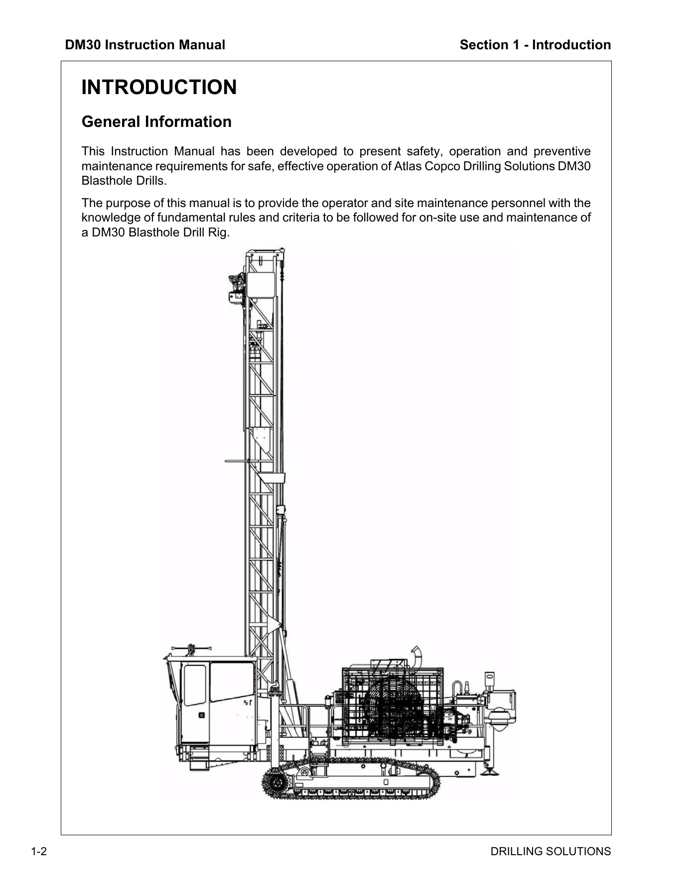
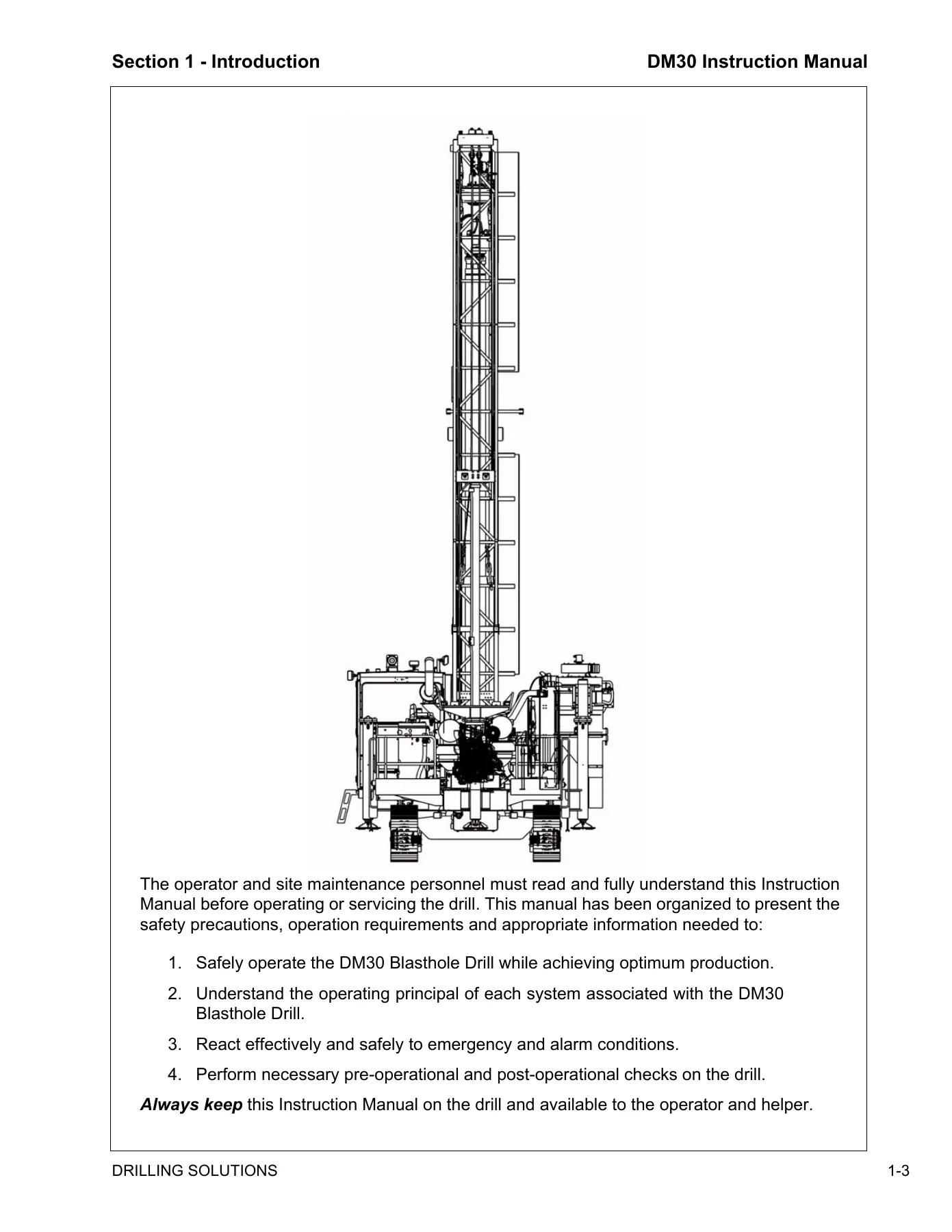
The Atlas Copco DM30 Blasthole Drill Instruction Manual is the complete factory-issued guide for the DM30 crawler-mounted, hydraulic tophead drive, multi-pass rotary drilling rig. This 2010 edition spans 534 pages and covers every phase of owning, operating, and maintaining the DM30 — from safety requirements and daily pre-start inspections through rotary drilling procedures, carousel rod handling, and the full scheduled maintenance program. Whether you are running the drill on a bench or overhauling the hydraulic system, this Atlas Copco DM30 Blasthole Drill Instruction Manual provides the procedures, specifications, and system explanations needed to do the job correctly.
File Details
- Manual Type: Instruction Manual
- Brand: Atlas Copco
- Model: DM30 Blasthole Drill
- Language: English
- Page Count: 534
- File Format: PDF
- Publication Year: 2010
- Publisher: Atlas Copco Drilling Solutions, LLC
Chapters Covered
- Section 1 — Introduction: General Information, How This Manual Is Organized, Procedure When Receiving Drill, Identification Data, Drill Identification, Engine Identification, Instruction Manual Location, Drill Description, Engine, Main Frame, Drill Tower, Operator’s Cab and Controls, Power Pack, Tramming (Propelling), Serviceability, Identification of Major Components
- Section 2 — Safety: Safety and Health, Safety and Health Statement, Emergencies, Important Safety Instructions, Safety Precautions and Guidelines, Warnings, Drill Applications, Designated Applications, Non-Designated Applications, Safety Reminder, Qualify Your Personnel, General Guidelines, Equipment Safety Rules, Pre-Start Inspection, Operation Safety, Setup and Start, Electrical Power Line Safety, Operating Safely, Drilling Safety, Propel (Tram) Safety, Stopping and Shutdown Safety, Sliding Fork, Maintenance Safety, Fueling, Batteries, Wire Rope and Cable, Hydraulic Maintenance Safety, Cylinder Repairs or Replacement, Pumps and Motors, Valves, Hoses, Coolers and Fans, Guards, Tracks, Lubrication, Compressor, Warning of Special Dangers, Overhead Electric Wires, Ventilation, Grade Limitations, Transportation Safety, Towing Safety, Safety Decals and Nameplates, Hazardous Substance Precaution, Symbol Identification
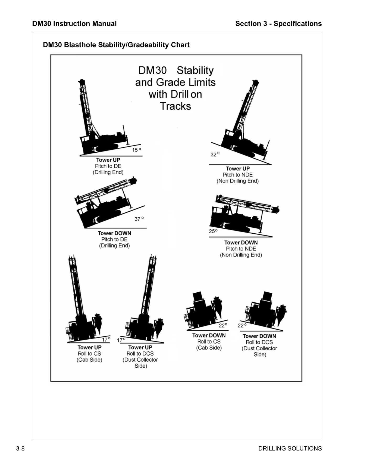
- Section 3 — Specifications: General Description, Drill Applications, Designated Applications, Non-Designated Applications, Design Features, Environment Rate Factor Ranges, Duty, Ambient Temperature, Service, Application Type, Operational Limitations, Ambient Temperature Range, Ground Pressure, Maximum Allowable Slope Angle, Operating Conditions for Stability, Sound Pressure Limitations, Vibration Exposure Limitations, DM30 Stability and Gradeability Chart, Standard Equipment and Specifications, Main Frame and Leveling Jacks, Undercarriage and Propel System, Tower Carousel and Drill Pipe Handling, Rotary Head, Carriage Feed System, Power Pack, Air Compressor, Hydraulic System, Operator’s Cab and Controls, Night Lights, Optional Equipment, Air Conditioner/Heater Package, Angle Drill Package, Angle Drilling/Sliding Table Package, Dust Control, Water Injection, Central Service System, Cold Weather Options, Optional Accessory Equipment, Rotary Head Float Sub, Ball Bearing Roller Deck Bushing, Standard Tools and Manuals, Operational Weights and Dimensions
- Section 4 — Controls: Operating Controls, Operator’s Console, Drill Function Panel, Drill Functions Panel Components, Gauges Function Panel, Gauges Function Panel Components, Engine Functions Panel, Compressor Functions Panel, Propel Functions Panel, Propel Functions Panel Components, Controls Not Located on Console Panels
- Section 5 — Operating Instructions: Walk Around Inspection, Check for Hydraulic System Oil Leaks, Check for Compressor System Oil Leaks, Check for Coolant System Leaks, Check for Fuel System Leaks, General Checks, Operator’s Areas, Pre-Start Inspection, Check Engine Oil Level, Check Engine Coolant Level, Check Fuel System Level, Drain Fuel Filter/Water Separator, Check Compressor Oil Level, Drain Receiver Tank Water, Check the Batteries, Pump Drive Gearbox Oil Level, Check Hydraulic Oil Level, Keep Operator’s Areas Clean, Pre-Operation Controls Inspection, Engine Operation, Starting Engine, Ether Cold Start, Verify Gauges and Controls, Water Temperature Gauge, Stopping Engine, Emergency Shutdown, Compressor Operation, Start/Run/Stop Procedures, Propel Operation, Recommendations and Checks, Hydrostatic Brake System Check Procedure, Stopping Drill Propel, Leveling the Drill, Tower Raising, Angle Locking, Tower Lowering, Overpressure Control System, Overpressure System Test, Carousel and Drill Rod Handling, DM30 Carousel, Drill Rod Loading, Initial Drill Rod Loading, Drill Rod Field Replacement, Adding Drill Rod Procedures, Adding Drill Rod to Drill String, Remove Drill Rod from Drill String, Drilling Procedures, Rotary Drilling, Rotary Drill String Tools and Accessories, Tricone Bit Installation Procedure, Rotary Drilling Procedure, Rotary Bit Changing Procedure, Chain Wrench, Angle Drilling, Stopping Parking and Shutdown, Stopping the Drill, Parking the Drill, Normal Shut Down, Emergency Shut Down, Daily Precautions After Work, Mounting and Dismounting of Equipment and Attachments, Towing the Drill, Special Conditions of Use, Cold Weather Conditions, Hot Weather Conditions, Water and Muddy Conditions, Dusty Conditions, High Altitude Conditions, Preservation and Storage
- Section 6 — Maintenance: Maintenance Safety and Health, Safety Precautions, Fluid Penetration, Lines Tubes and Hoses, Burn Prevention, Coolant, Oils, Batteries, Fire or Explosion Prevention, Fire Extinguisher, Crushing or Cutting Prevention, Mounting and Dismounting, Before Starting the Engine, Engine Starting, Starting Aids, Engine Stopping, Maintenance Information, Handling Fluids and Oil, Maintenance Schedule, Refill Capacities/Lubricants, Hazardous Substance Precaution, Lubrication Table, Refill Capacities, AW32 Hydraulic Oil, Compressor Fluid, Lubricant Viscosities, Lubricant Oil, Pump Drive Oil, Final Drive Lubricating Oil, Hoist Lubricant, Water Injection Pump Lubricant, General Grease, Central Lube System Grease, Multi-Purpose Grease, Rotary Head Grease, Engine Lubricating Oil, Engine Coolant Specifications, CAT Fuel Oil, Maintenance As Required, Air Cleaner, Air Cleaner Indicators, Connections and Ducts, Empty Dust Cups, Air Cleaner Pre-Cleaner, Air Cleaner Rain Guard, Air Cleaner Elements, Air Cleaner Service Tips, Clean the Drill, Loose Bolted Connections, Feed Cable and Wire Rope, Cable Lubrication, Feed Cable Replacement, Wire Rope, Wire Rope Clamps, Wire Rope Installation, Grease Drum Option, Maintenance (8-10 Hours), Overpressure System Test, Air Cleaners, Engine, Engine Oil Level, Engine Belts and Tensioner, Drive Belts Inspection, Belt Replacement, CAT Engine Belts, Belt Adjustment, Engine Fuel/Water Separators, CAT Fuel/Water Separator, Cooling System Maintenance, Radiator Coolant Level, Cooling System Sealing Additives, Cooling System Soluble Oils, Clean Radiator and Oil Coolers, Fuel Tank, Fuel Level, Receiver Separator, Drain Water from Receiver Tank, Compressor Oil Level, Oil Carry Over, Change Receiver Separator Element, Hydraulic Reservoir, Hydraulic Oil Level, Hydraulic Oil Filters, Rotary Head, Rotary Head Oil Level, Rotary Head Upper Bearing, Gearbox Driveshaft, Grease Gearbox Drive Shaft Universal Joints, Dust Collector, Dropout Hose, Suction Hose, Blower Assembly, Filter Elements, Rod Seal, Housekeeping, Clean the Drill, Loose Bolted Connections, Maintenance (50 Hours or Weekly), Batteries, Electrolyte Level, Battery Terminals, Pump Drive Gearbox, Oil Leaks, Check Oil Level, Undercarriage, Initial Break-In Maintenance, Final Drive Mounting Bolts, Oil Leaks, Oil Level Final Drive, Tracks, Track Tension, Track Adjustment, Auxiliary Hoist, Periodic Inspection, Wire Rope, Maintenance (100 Hours), Auxiliary Hoist, Oil Change, Mounting Bolts, Maintenance (150 Hours), Track Planetary Gearbox, Final Drive Mounting Bolts, Change Initial Track Planetary Oil, Maintenance (250 Hours), CAT Engine Maintenance, Engine Lubricating Oil and Filters, Drain Engine Oil, Replace Engine Oil Filter(s), Fill Engine Crankcase, Cat Secondary Fuel Filter(s), CAT Coolant Filter, Engine SCA Level, Engine Valve Lash, Auxiliary Hoist, Wire Rope Condition, Maintenance (500 Hours), Batteries, Batteries Clamps and Cables, Fuel Tank, Fuel Tank Breather, Hydraulic Reservoir, Hydraulic Tank Breathers, Hydraulic Fluid Condition Limits, Change Hydraulic Oil, Drain Hydraulic Reservoir, Refill Hydraulic Reservoir, Compressor, Compressor Oil Strainer, Compressor Oil Filter, Pump Drive Gearbox, Change Initial Oil, Auxiliary Hoist, Check Oil Level, Cable/Rope Lubrication, Compressor Air Hose and Clamps, Air Hose and Clamps, Maintenance (1000 Hours), Compressor Oil, Change Compressor Oil, Change Compressor Oil Filter, Hydraulic Oil Filters, Replace Hydraulic Return Filters, Replace Hydraulic Drain Filter, Rotary Head, Change Rotary Head Oil, Pump Drive Gearbox, Change Initial Oil, Auxiliary Hoist, Oil Change, Mounting Bolts, Maintenance (1500 Hours), Track Planetary Gearbox, Change Initial Track Planetary Oil, Maintenance (2000 Hours), Air Cleaners, Primary and Safety Elements, Compressor Discharge Hose, Engine Belts and Tensioner, Maintenance (5000 Hours), Hydraulic Reservoir, Change Hydraulic Oil, Drain Hydraulic Reservoir, Refill Hydraulic Reservoir, Maintenance (6000 Hours), Engine Coolant, Drain Cooling System, Flush Cooling System, Fill the Cooling System, Torque Specifications, Standard Torque Values, Head Markings, Recommended Torques in Foot Pounds, Recommended Torques in Nm
- Section 7 — Troubleshooting: System and Troubleshooting, Troubleshooting Information, Electrical Controls, Operator Observed Problems, Pneumatics, Mechanical Hydraulic Components, Mechanical Engine, Electrical, General Information, Electrical System Information, CAT Engines, Batteries, Fusible Links, Starter Motor, Alternator, Key Switch, Circuit Breakers, Push Buttons, Engine Shutdown Devices, Compressor Discharge Temperature Switch, CAT Engine Electronics, Indicator Light System, C15 Diagnostic Fault Codes, Diagnostic Switch, Incremental Switch, Finding Fault Codes, Reading Fault Codes, Fault Code Example, CAT Engine Diagnostic Codes, Event Codes, Fault Logging, Engine Operation with Active Diagnostic Codes, Engine Operation with Intermittent Diagnostic Codes, Murphy Link Powerview System, Description, Faceplate Features and Keypad Functions, Mechanical Installation, Electrical Installation, Powerview Operation, Main Menu Navigation, Selecting a Language, Stored Fault Codes, Engine Configuration Data, Faults and Warnings, Active Fault Codes, Shutdown Codes, BackLight Adjustment, Contrast Adjustment, Select Units, Setup 1-Up Display, Setup 4-Up Display, Utilities, MODBUS Setup, Glossary, CANBUS Failure, No Data, Not Supported, DATA Error, EMPTY, WAIT TO START PREHEATING, Time-out ECU Not Responding, NO GAGE Data, Electric Ladder, Electrical Symbols, Electrical System Information, Operator Observed Problems, Compressor, Pneumatic System Information, Adjustment of the Pneumatic Regulating System, Compressor Fire Prevention, Lubrication System, Lubrication System Components, Receiver Separator Tank, Strainer, Thermostatic Valve, Oil Cooler, Oil Filter, Discharge Check Valve, Compressor Oil, Oil Flow, Separation System, Blowdown Valve, Receiver Tank, Minimum Pressure Valve, Safety Relief Valve, Service Connection, Pressure Gauge, Compressor Related Problems, Hydraulic System, Hydraulic System Introduction, Hydraulic Symbols, Fluid Power Symbols, Line Symbols, Crossing Line Symbols, Joining Line Symbol, Flexible Line Symbol, Arrow Symbols, Reservoir or Tank Symbols, Fluid Container Symbols, Accumulator Symbols, Restrictor Symbols, Hydraulic Cylinders, Activating Device Symbol, Miscellaneous Symbols, Pump and Motor, Pump Symbols, Hydraulic Motor Symbols, Instrument Symbols, Valves, Three Position 4 Way Valve, Valve Centers, Series Parallel Valve, Manual On-Off Valve, Pressure Relief Valve, Sequence Valve, Pressure Reducing Valve, Check Valve, Pilot Operated Lock Check Valve, Bypass Valve, Overcenter Valve, Propel System, Propel Circuit, Components, Main Hydraulic Pumps, Propel Motors, Propel Motor Brake, Diverter Valve Assembly, Propel/Drill Mode Selector, Drill/Propel Control Valve, Loop Filling/Replenishment, Loop Flushing Circuit, Circuit Operation, Oil Path Selection, Feed and Rotation System, Feed System, Mechanical System, Hydraulic System, Feed, Feed Pump, Feed Cylinders, Feed Carriage, Over Center Valve, Pressure Control Valve, Two-Way Valve, Diverter Valve Assembly, Drill/Propel Control Valve, Remote Compensator Control, Jack Two-Way Valves, Over Pressure Control, Over Pressure System Test, Feed Circuit Operation, Oil Path Selection, Cylinder Extend and Retract, Loop Filling/Replenishment, Rotation System, Main Pump, Rotation Motors, Rotation Motor Displacement Adjustment, Rotation Motor Control Valve, Rotation Circuit Operation, Rotation, Motor Displacement Control, Drill/Propel Control Valve, Oil Path Selection, Loop Filling/Replenishment, Auxiliary Function Circuit, Auxiliary Functions, Components, Double Pump, P1 Pump Circuit, P2 Pump Circuit, Motors, Cylinders, Relief Valves, Check Valves, Two Way Valve, Holding Valves, Pilot Check Valves, Fourteenth Spool Valve, 14-Spool Valve Stack Sections, P2 Pump Circuit, Circuit Operation, Cooling Circuit, Fan Motor, Circuit Operation, Manifold System, Return Manifold, Drain Manifold, Supercharge Manifold, Filter Assembly, Hydraulic Reservoir, Circuit Operation, Service Notes, Pressure Test Ports, Hydraulic Fluid, Fluid Sampling, Hydraulic Connections, Electro Hydraulic System, Overview, General Concepts and Terminology, Current Control, Pulse Width Modulation, Threshold, Maximum Out, Controllers, Dual Range, Single Coil Controllers, Dual Coil Controllers, Denison 900 Stroker, Adjustment Procedure for 9A Controls on a Goldcup Pump, Valves, Apitech Pulsars, 14-Spool Valve First Stack, Holding Valve, Controllers, Pulldown Controller, Water Injection Rotary Activated Controller, Limit Switches, Relays, DPDT 24 VDC Relay, Typical Coil Resistance, Denison Stroker Coil, Adjustments, Apitech Coils, Fema Coils, Proportional Remote Control Output, Checking Relay, Checking Limit Switch, Checking Diode, EHC Operation, Operation, Jack Controllers, Hoist Controller, Tower Raising Controller, Rod Indexer Controller, Breakout Fork Wrench Controller, Carousel Swing Controller, Water Injection Controller, Dust Collector, Tower Pinning, Tower Angle Leg Pinning, Drill Propel Valve, Drill Feed Circuit, Rotation Control, Drill Feed and Rotation Controller, Drill Feed Force/No Bump Rod Changer, Rotation Control, Torque Limit Control, EHC Adjustments, Feed and Rotation Controllers, Main Pump Controller Setting, Main Pump Controller Settings Propel Controls, Auxiliary Function Controllers, Pulldown Force Rotary Controller, Troubleshooting (Dust Collector), Dust Collector, Upper Tap HIGH Lower Tap LOW, Upper Tap HIGH Lower Tap HIGH, Upper Tap LOW Lower Tap LOW, Dust Collector Trouble Shooting Guide, Setting the Electric Timer, Troubleshooting (Centromatic Lube), General Information, Principle of Operation, Typical System Drawing, Fill Supply Line, Prime Feed Lines, Operation Check, Attach Air Motor to Pump Tube, Failures without Alarm Systems, Failures with Alarm Systems, Dixon Boss Clamp Selection and Installation, Safety Information, MSHA Regulations, S.T.A.M.P.E.D., General Preparation Instructions, Dixon Diameter Tape Procedures, Procedure, Boss Clamps, Boss Clamp Selection, Additional Information, Criteria For Sufficient Fit of a Boss Clamp, Minimum Range, Maximum Range, Installation of Boss 2 Bolt Clamp, Installation of Boss 4 Bolt Clamp, Installation of Boss 6 Bolt Clamp, Testing, Hydrostatic Testing, Electrical Continuity Testing
- Section 8 — Glossary: Glossary of Terms
What This Manual Gives You
This is not a quick-start leaflet. The Atlas Copco DM30 Instruction Manual is a full technical reference covering the machine from the tracks up. Section 3 alone delivers complete specifications for the main frame, leveling jacks, undercarriage and propel system, tower, carousel, rotary head, carriage feed system, power pack, air compressor, hydraulic system, operator’s cab, and the optional equipment packages including angle drilling, dust collection, water injection, and cold weather options. Section 4 walks through every control and gauge on the operator’s console, explaining what each instrument monitors and how it responds during drilling.
Section 5 provides step-by-step operating procedures for engine start-up, compressor operation, tramming, leveling, tower raising and pinning, carousel rod handling, adding and removing drill rod from the string, rotary drilling technique, tricone bit installation and replacement, angle drilling setup, and shutdown. The drill rod loading and field replacement procedures are covered in detail, including the initial carousel loading and the five-rod configuration. Angle drilling setup covers the locking pin sequence and the tower positioning increments.
Section 6 is the complete maintenance program, organized by service interval from 8-10 hours through 6000 hours, with refill capacities, lubricant specifications, torque values, and detailed procedures for the engine, compressor, hydraulic system, rotary head, undercarriage, auxiliary hoist, and dust collector. The maintenance schedule tables list every service item and its interval, while the refill capacities table gives the exact quantities for hydraulic oil, compressor oil, engine coolant, engine oil, fuel, and gearbox lubricants. The torque specification tables cover standard and metric values for all bolt sizes and grades used on the machine.
Section 7 is the troubleshooting reference, covering the electrical system with CAT engine diagnostics and fault codes, the Murphy Link PowerView system, the compressor, the hydraulic system and its symbols, the propel system, the feed and rotation system, the auxiliary function circuit, and the electro-hydraulic controls with adjustment procedures. The hydraulic symbol glossary is a complete visual reference for reading the schematic diagrams. The electro-hydraulic section explains the proportional and on/off control links, the Denison stroker, the Apitech pulsars, and the FEMA pressure controller, with adjustment procedures for the feed, rotation, and propel controllers. The dust collector and Centromatic lube troubleshooting sections provide diagnostic guidance for those systems. Section 8 provides a glossary of drilling and equipment terms.
Specifications and Technical Data
The DM30 is documented as a complete machine. Engine coverage includes the CAT C15 diesel rated at 475 hp @ 1800 rpm, with references to Cummins engines where applicable. The manual documents the DM30’s 30,000 lb bit loading capability, 5 in. to 6-3/4 in. hole diameter range, multi-pass depth capability up to 149 feet using 30 ft drill pipe, and the 1050 CFM @ 110 psi air compressor. The rotary head is rated at 5,400 ft-lbs torque with a 0-100 RPM speed range. The feed system delivers 0 to 30,000 lbs weight on bit with a 200-inch cylinder stroke. Undercarriage, leveling jack, rotary head, feed cylinder, and hydraulic system specifications are presented with the actual numbers — pressures, capacities, dimensions, and torque values. The hydraulic system pressures table lists rotation and propel at 4,500 psi, feed at 3,500 psi pulldown and pullback, and auxiliary circuits at 3,000 psi. The refill capacities table gives hydraulic tank at 378.5 liters, fuel tank at 871 liters, engine coolant at 166 liters, and engine oil at 32.18 liters for the CAT C15.
Who This Manual Is For
The Atlas Copco DM30 Blasthole Drill Instruction Manual is written for the operator, the site maintenance technician, and the shop mechanic. Operators will use the safety, controls, and operating sections to run the drill correctly and recognize developing problems. Maintenance personnel will rely on the scheduled maintenance procedures, torque specifications, lubricant tables, and troubleshooting charts to keep the drill running and diagnose faults. The safety section, including the full safety decal and nameplate listing with part numbers and locations, is essential for anyone working around the machine.
Get the Complete DM30 Reference
Having the correct procedures and specifications on hand is what separates efficient, safe operation from guesswork. This Atlas Copco DM30 Blasthole Drill Instruction Manual puts the manufacturer’s operating instructions, maintenance schedules, specifications, and troubleshooting guidance in one document you can keep on the drill or in the shop. Instant PDF delivery after payment — no shipping, no waiting. Read it on any device, print the pages you need for the job, and keep the reference available whenever a procedure or specification question comes up.
IMAGES PREVIEW

Reviews
There are no reviews yet.