
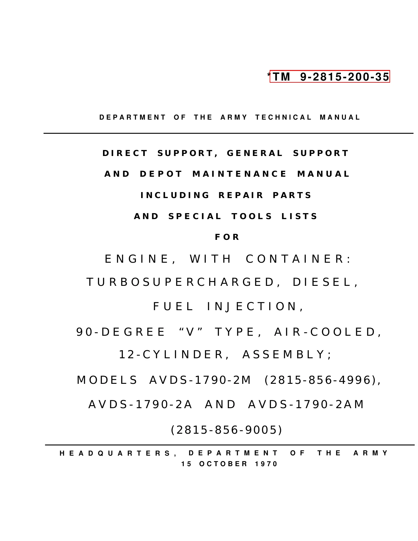
AVDS-1790-2M 2A 2AM Engine Direct Support & Depot Maintenance Manual TM 9-2815-200-35
Original price was: $44.95.$27.95Current price is: $27.95.
Complete US Army direct support, general support and depot maintenance manual for the AVDS-1790-2M, AVDS-1790-2A and AVDS-1790-2AM 12-cylinder air-cooled diesel engines, including troubleshooting, overhaul procedures, repair parts and special tools lists.
Description
AVDS-1790-2M 2A 2AM Engine Maintenance Manual TM 9-2815-200-35
This is the full TM 9-2815-200-35 Direct Support, General Support and Depot Maintenance Manual for the AVDS-1790-2M (FSN 2815-856-4996), AVDS-1790-2A and AVDS-1790-2AM (FSN 2815-856-9005) engines. These are turbosupercharged, diesel, fuel injection, 90-degree “V” type, air-cooled, 12-cylinder assemblies manufactured by Continental Motors Corp. The manual covers engine maintenance at the direct support, general support and depot levels, including removal, troubleshooting, disassembly, inspection, repair, reassembly, testing, repair parts and special tools.
File Details
- Manual Type: Direct Support, General Support and Depot Maintenance Manual including Repair Parts and Special Tools Lists
- Document Number: TM 9-2815-200-35
- Date: 15 October 1970
- Supersedes: TM 9-2815-200-34 (February 1963), TM 9-2815-200-35 (August 1960), TM 9-2815-200-35P (November 1962) and all published changes
- Engines Covered: AVDS-1790-2M, AVDS-1790-2A, AVDS-1790-2AM
- Manufacturer: Continental Motors Corp.
- Language: English
- Page Count: Approximately 780 pages
- File Format: PDF
Chapters Covered
- Chapter 1 – Introduction
- Section I. General
- Section II. Description
- Differences Between Engine Models
- Location of Engine Components
- General Description
- Accessories
- Crankcase
- Main Bearings
- Crankshaft, Flywheel, and Damper
- Connecting Rods and Bearings
- Pistons, Pins and Rings
- Cylinders and Valves
- Camshafts
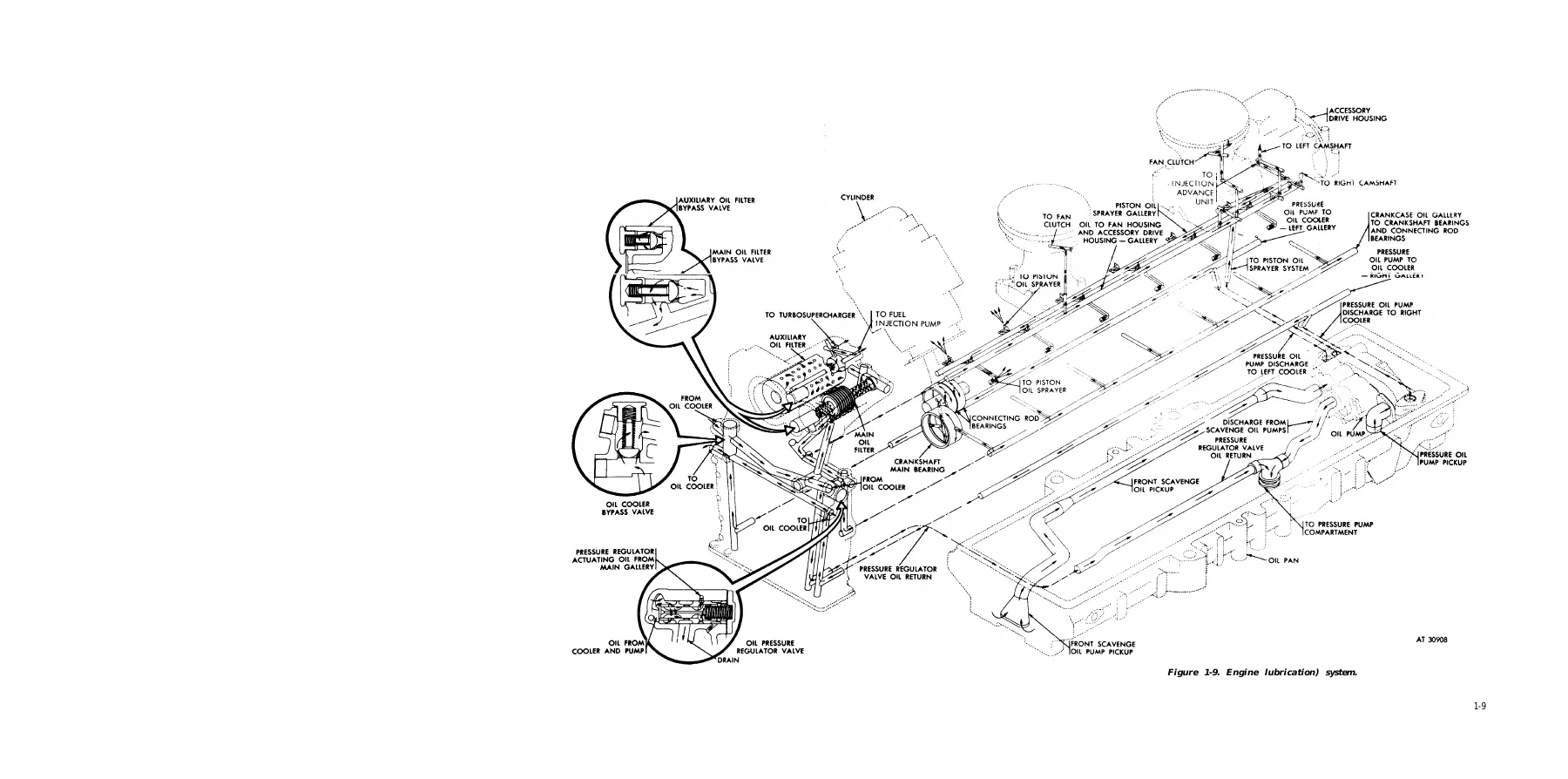
- Lubrication System
- Fuel System
- Manifold Air Induction and Heater System
- Exhaust System and Turbosupercharger
- Cooling System
- Crankcase Breather and Fire Extinguisher Systems
- Sending Units and Switches
- Engine Specifications
- Drive Ratios and Rotation
- Chapter 2 – Parts, Special Tools and Equipment, Improvised Tools and Shop Layout
- Section I. Repair and Replacement Parts
- Section II. Special Tools and Equipment
- Section III. Shop Layout
- Chapter 3 – Troubleshooting
- Section I. General
- Section II. Troubleshooting Procedures
- Engine Assembly
- Starting System
- Generating System
- Air Intake System
- Fuel System
- Lubricating System
- Cooling System
- Intake Manifold Flame Heater Fuel System
- Chapter 4 – Replacement of Engine Accessories, Components and Related Service Operations
- Section I. General
- Section II. Removal or Installation of Engine Accessories
- Section III. Main Valve, Oil Pressure Fuel/Water and Auxiliary Oil Filter Bypass Regulator Valve and Separator Filter
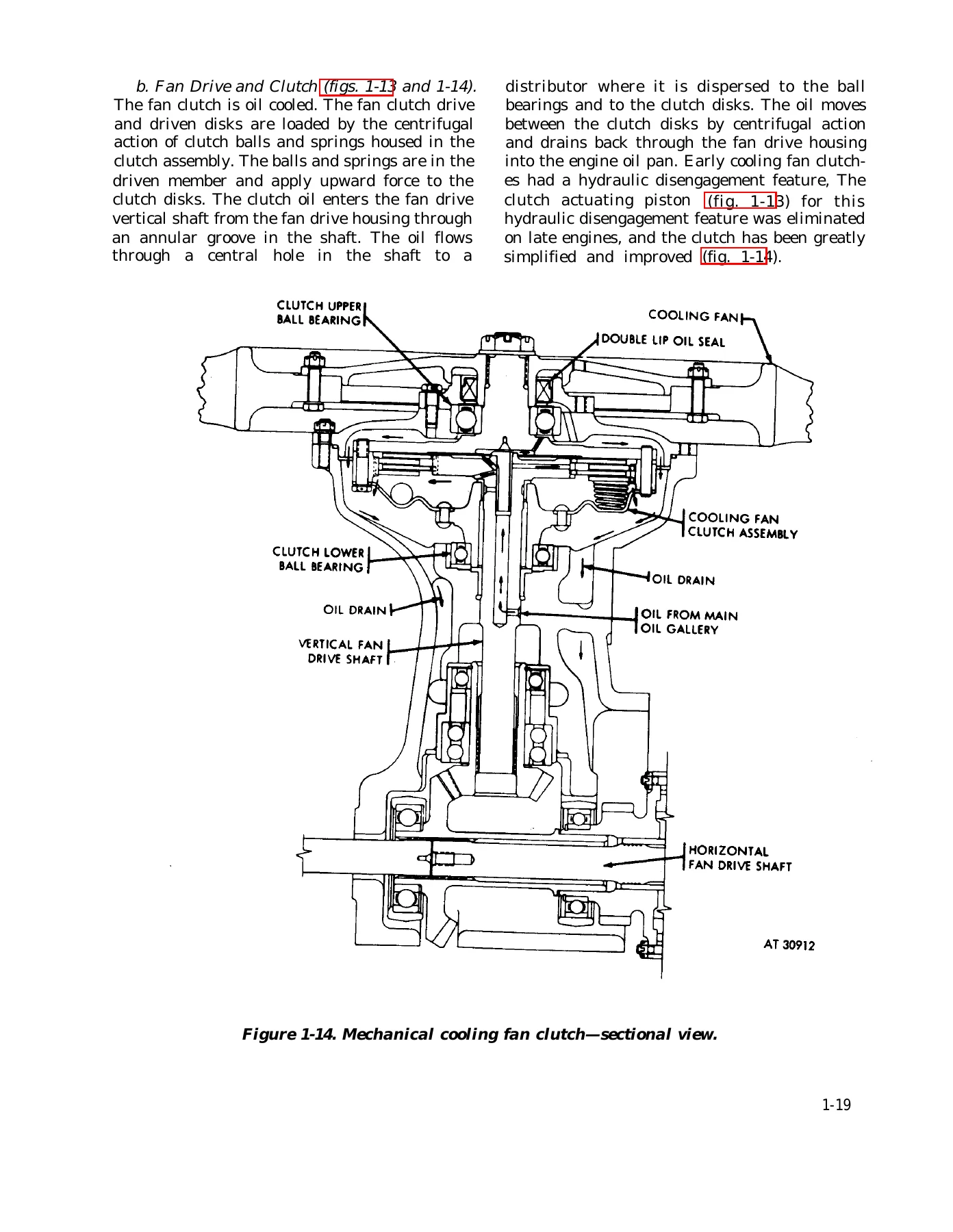
- Section IV. Cooling Fan Clutch Assembly and Fan Drive Housing Outer Flange Bearing
- Section V. Intake Manifold Tubes and Intake Manifold Assembly
- Section VI. Engine Oil Pan
- Section VII. Valve Rocker Arms, Rocker Arm Shafts and Valve Clearance Adjusting Screws
- Section VIII. Fuel Injector Nozzle and Holder Assembly
- Section IX. Flywheel and Crankshaft Oil Seal
- Section X. Service Operations (Cylinder Compression, Valve Clearance, Valve Timing)
- Chapter 5 – Disassembly of Engine
- Section I. Preparation of Engine for Disassembly
- Section II. Installation of Engine on Overhaul Stand for Disassembly into Subassemblies
- Chapter 6 – Overhaul of Engine Components
- Section I. General Cleaning, Inspection, Repair and Assembly Procedures
- Section II. Crankcase Assembly, Transmission Adapter, and Starter and Generator Drive Components
- Section III. Connecting Rod, Crankshaft and Associated Parts
- Section IV. Torsional Vibration Damper, Flywheel, Accessory Drive Gear and Transmission Drive Gearshaft
- Section V. Pistons, Rings and Piston Pins
- Section VI. Cylinder Assembly
- Section VII. Oil Pump, Oil Pan, Damper and Oil Filter Housing and Associated Parts
- Section VIII. Front Fan Drive Housing and Clutch Assembly
- Section IX. Rear Fan Drive Housing and Clutch Assembly and Accessory Drive Housing
- Section X. Camshaft and Throttle Control Cross Shaft and Fuel Injection Pump Linkage
- Section XI. Engine and Transmission Oil Coolers and Engine Cooling Fan
- Section XII. Engine Shrouding and Associated Parts
- Section XIII. Intake Manifolds, Exhaust Manifolds and Tubes, Cylinder Head Oil Drain Tubes, and Oil Filler and Indicator Tubes
- Section XIV. Generator and Starter Supports, Fuel Check Valve, Primary and Secondary Fuel Filters, and Fuel/Water Separator
- Section XV. Fuel Injection Pump Fuel Tubes, Fuel Injector Nozzle Fuel Return Tubes, Injection Pump and Turbosupercharger Oil Hoses, and Generator Air Intake and Exhaust Tubes
- Section XVI. Crankcase Breather Tubes, Fire Extinguisher Tube, Injection Pump Electrical Lead, and Manifold Heater Fuel Tubes, Filter and Electrical Components
- Section XVII. Fuel Injection Pump Drive Couplers, Fuel Injector Nozzles, Piston Oiler Nozzles and Time Totalizing Meter
- Chapter 7 – Assembly of Engine
- Section I. General
- Section II. Assembly of Engine from Subassemblies
- Chapter 8 – Engine Test and Engine Container
- Section I. Engine Test and Adjustments
- Section II. Engine and Container
- Index
- Appendix A – References
- Appendix B – Direct Support, General Support and Depot Maintenance Repair Parts and Special Tools List
- Section I. Introduction
- Section II. Repair Parts (Engine, Fuel System, Cooling System, Electrical System, Special Purpose Kits, Electrical Equipment)
- Section III. Special Tools
- Section IV. General Use Standardized Parts
- Section V. Federal Stock Number and Ordnance Part Number Indexes
What This Manual Provides
The AVDS-1790-2M 2A 2AM engine is a 12-cylinder, 90-degree V-type, four-cycle, air-cooled, turbosupercharged diesel producing 750 bhp at 2400 rpm with a 1790 cubic inch displacement. This TM 9-2815-200-35 manual is the comprehensive maintenance guide used at direct support, general support and depot levels. It covers everything from replacing individual accessories to complete engine disassembly and overhaul, component inspection and repair, reassembly, dynamometer testing and storage in the reusable shipping container.
Troubleshooting charts in Chapter 3 cover the engine assembly, starting system, generating system, air intake system, fuel system, lubricating system, cooling system and the intake manifold flame heater fuel system, listing malfunction, probable cause and corrective action. Chapter 4 covers replacement of engine accessories including the fuel pump, starter, generator, turbosupercharger and fuel injection pump, plus main and auxiliary oil filter bypass valves, oil pressure regulator, fuel/water separator filter, cooling fan clutch, intake manifold tubes, oil pan, valve rocker arms, fuel injector nozzles, flywheel and crankshaft oil seal.
Chapter 6 is the overhaul heart of the manual, covering the crankcase, transmission adapter, starter and generator drive components, connecting rods, crankshaft, torsional vibration damper, flywheel, accessory drive gear, transmission drive gearshaft, pistons, rings, piston pins, cylinder assemblies, oil pump, oil pan, damper and oil filter housing, front and rear fan drive housings and clutch assemblies, camshafts, throttle control cross shaft and fuel injection pump linkage, engine and transmission oil coolers, cooling fan, engine shrouding, intake and exhaust manifolds, cylinder head oil drain tubes, oil filler and indicator tubes, generator and starter supports, fuel check valve, fuel filters, fuel/water separator, fuel injection pump fuel tubes, fuel injector nozzle fuel return tubes, injection pump and turbosupercharger oil hoses, generator air intake and exhaust tubes, crankcase breather tubes, fire extinguisher tube, injection pump electrical lead, manifold heater fuel tubes and filter, fuel injection pump drive couplers, fuel injector nozzles, piston oiler nozzles and the time totalizing meter.
Chapter 7 covers assembly of the engine from subassemblies including starter drive gearshaft, generator and idler gears, piston oiler nozzles, crankshaft and connecting rod assembly, accessory drive gear, crankshaft oil seal, transmission adapter, flywheel, starter and generator drive adapters, vibration damper, sending units, oil pump, oil tubes, pistons and pins, cylinder assemblies, cylinder air deflectors, crankshaft damper and oil filter housing, oil pan, fan drives, housings, bases, camshafts, fuel injection pump, rocker arm covers, nozzle and holder assemblies, cylinder deflectors, shrouds, turbosupercharger oil inlet hose, fire extinguisher tube, fuel injection pump oil inlet hose, throttle control rods and lever, turbosupercharger base, supports, tie rods, fuel inlet and return hoses, crankcase breather tubes, exhaust pipes and manifolds, fuel injector clamps, supports and tubes, oil filler and indicator tubes, rear and front shrouds, throttle linkage, fuel filters, intake manifold assemblies, cylinder head oil drain lines, manifold heater tubes, solenoids and filter, oil coolers, beams, cooling fans, shrouding and engine accessories.
Chapter 8 covers engine test and adjustments including speed range, gross horsepower, gross torque, oil consumption, fuel consumption, exhaust gas temperature, blow-by pressure, lubricating oil temperature, oil pressure, temperatures, fuel pressure, manifold pressure and exhaust smoke density. It also includes crankcase and induction system leakage test, fuel and oil system leakage test, engine run-in, engine test and adjustments, inspection of cylinders for scuffing using a borescope, quality control test, and engine container disassembly, reconditioning, preservation, installation and periodic inspection.
Appendix B provides a complete illustrated repair parts and special tools list with exploded views covering the engine assembly, crankcase, cylinder head, crankshaft, flywheel assembly, pistons, connecting rods, valves, camshafts, timing system, engine lubrication system, manifolds, accessory driving mechanisms, fuel system, fuel injector, fuel pumps, lines and fittings, turbosupercharger, engine speed governor and controls, fuel filters, engine starting aids, cooling system, deflectors and shrouds, fan assembly, electrical system, generator, starting motor, sending units and warning switches, special purpose kits, reusable shipping containers, instruments, special tools and general use standardized parts. Federal stock number and ordnance part number indexes are also included.
Why This Manual Matters
The AVDS-1790 series engines powered the M60, M60A1 and M48A3 tanks, the M728 Combat Engineer Vehicle and the M60A1 Tank Chassis Transporting Launcher. Proper maintenance, troubleshooting and overhaul of these 12-cylinder air-cooled diesels require access to the exact procedures, torque values, clearances, wear limits and parts information that this manual provides. Whether you are replacing a fuel injector nozzle, rebuilding a fan drive clutch, timing the fuel injection pump, overhauling the crankshaft and connecting rod assembly, or testing the engine on a dynamometer, this manual gives you the step-by-step instructions, illustrations and specifications needed to complete the job correctly.
Instant PDF Delivery
This AVDS-1790-2M 2A 2AM engine maintenance manual is delivered as an instant PDF download after payment. No shipping, no waiting. The file can be viewed on any device, searched for specific procedures, and printed for use in the shop or motor pool. Whether you are maintaining a single engine or running a depot overhaul line, this TM 9-2815-200-35 manual gives you the complete direct support, general support and depot maintenance information for the AVDS-1790-2M, AVDS-1790-2A and AVDS-1790-2AM engines.
Reviews
There are no reviews yet.