
Bauer B 28.3 Medium Pressure Industrial Air Compressor Instruction Manual & Replacement Parts List
Original price was: $39.95.$23.95Current price is: $23.95.
Complete instruction manual and illustrated replacement parts list for the Bauer B 28.3 medium pressure industrial air compressor, covering the IK28.3 Mod. 2 compressor block, Maple System touchscreen operation, automatic condensate drain, drive system and the ASY-1068 XL electrical panel.
Description
Bauer B 28.3 Industrial Air Compressor Manual and Parts List
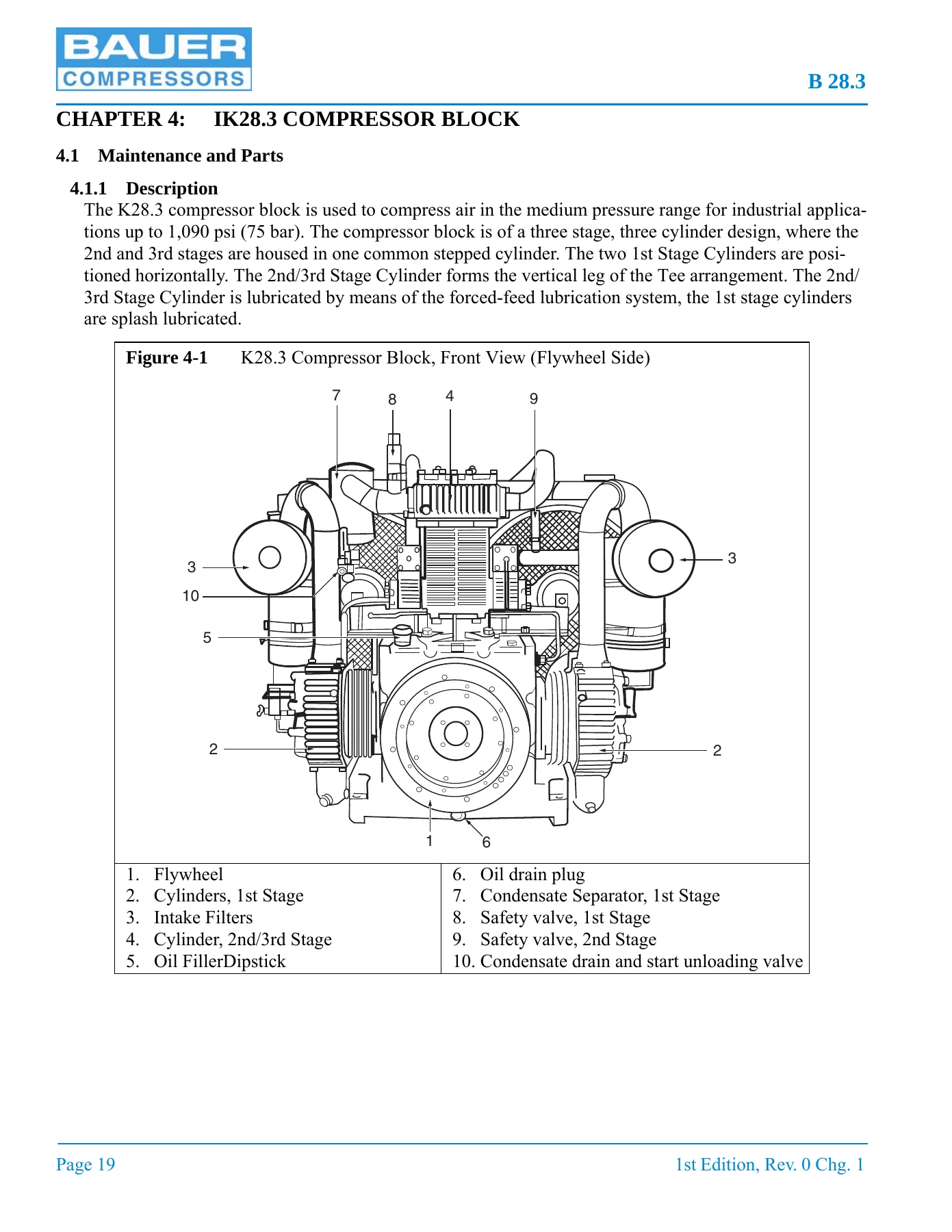
This is the full instruction manual and replacement parts list for the Bauer B 28.3 medium pressure industrial air compressor. It is written for the people who actually run and service the machine: operators working the Maple System touchscreen, and maintenance technicians tearing down valve heads, resetting oil pressure, tensioning V-belts or chasing a compressor that will not build final pressure. Everything in it is specific to this unit, from the 206 scfm / 1,080 psig ratings and the IK28.3 Mod. 2 three-stage block, right down to the individual O-rings, gaskets and stud part numbers for each assembly.
File Details
- Manual type: Instruction Manual and Replacement Parts List
- Brand: Bauer Compressors, Inc.
- Model: B 28.3 Medium Pressure Industrial Air Compressor
- Compressor block: IK28.3 Mod. 2
- Document number: MNL-114723
- Edition: 1st Edition, Rev. 0, Chg. 1
- Dates: 1st Edition August 26, 2010; Change 1 November 17, 2011
- Language: English
- Page count: 122 pages
- File format: PDF
Chapters Covered
- Chapter 1: Introduction — how to use the manual, manual safety notices, how to use the replacement parts list, how to use the appendix, specifications (B 28.3, compressor block, compressor drive, purification system applicability)
- Chapter 2: Operating Instructions; Maple System — description, emergency stop button, operator interface, run screen, main menu screen (Run, Alarms, Login, Logout, Status, Parameters, Configuration, Tools, Contact), starting and stopping the unit, screen flow
- Chapter 3: Indicators & Valves — description, replacement parts list, nonadjustable valves, pressure maintaining valve and PMV adjustment, safety valves
- Chapter 4: IK28.3 Compressor Block — maintenance and parts, air flow diagram, lubrication system (oil level check, oil change procedure, oil filter and removal, oil pump, oil pressure setting, oil strainer, oil jet), cooling system and maintenance, compressor valves and valve heads, changing 1st/2nd stage valves, changing 3rd stage valves, intake filter and dust collector, intermediate and final separators, oil and water separator, replacement parts list, troubleshooting, repair instructions, piston ring gap, automatic condensate drain system, condensate separator
- Chapter 5: Compressor Drive System — horizontal sliding description, V-belt and sheave maintenance, checking the sheave, checking the V-belt, V-belt tension, drive motor/engine maintenance, replacement parts list
- Chapter 6: Electrical Panel, ASY-1068 XL — overview, wiring diagram, panel interior access, optional equipment, AC power requirements, panel components (PLC, replacing the PLC, installing a new program, installing an EEPROM, hourmeter, transformer and fuses, motor starter, soft start, starter reset, optional communication modules, power supply), alarms, PLC inputs and outputs, analog inputs, wiring harness layout, replacement parts lists for 75 HP, 100 HP and 150 HP motor models
- Chapter 7: Appendix — safety, general safety precautions, safety warning labels, unpacking/handling/installation, ventilation (outdoor, indoor, natural, forced), electrical installation and supply, pneumatic leaks, long term storage, preserving the compressor, reactivating the compressor unit, reproducible forms, reference data, tightening torque values, torque sequence diagrams, conversion formulas, approved lubricants chart, glossary of abbreviations and acronyms, additional documents
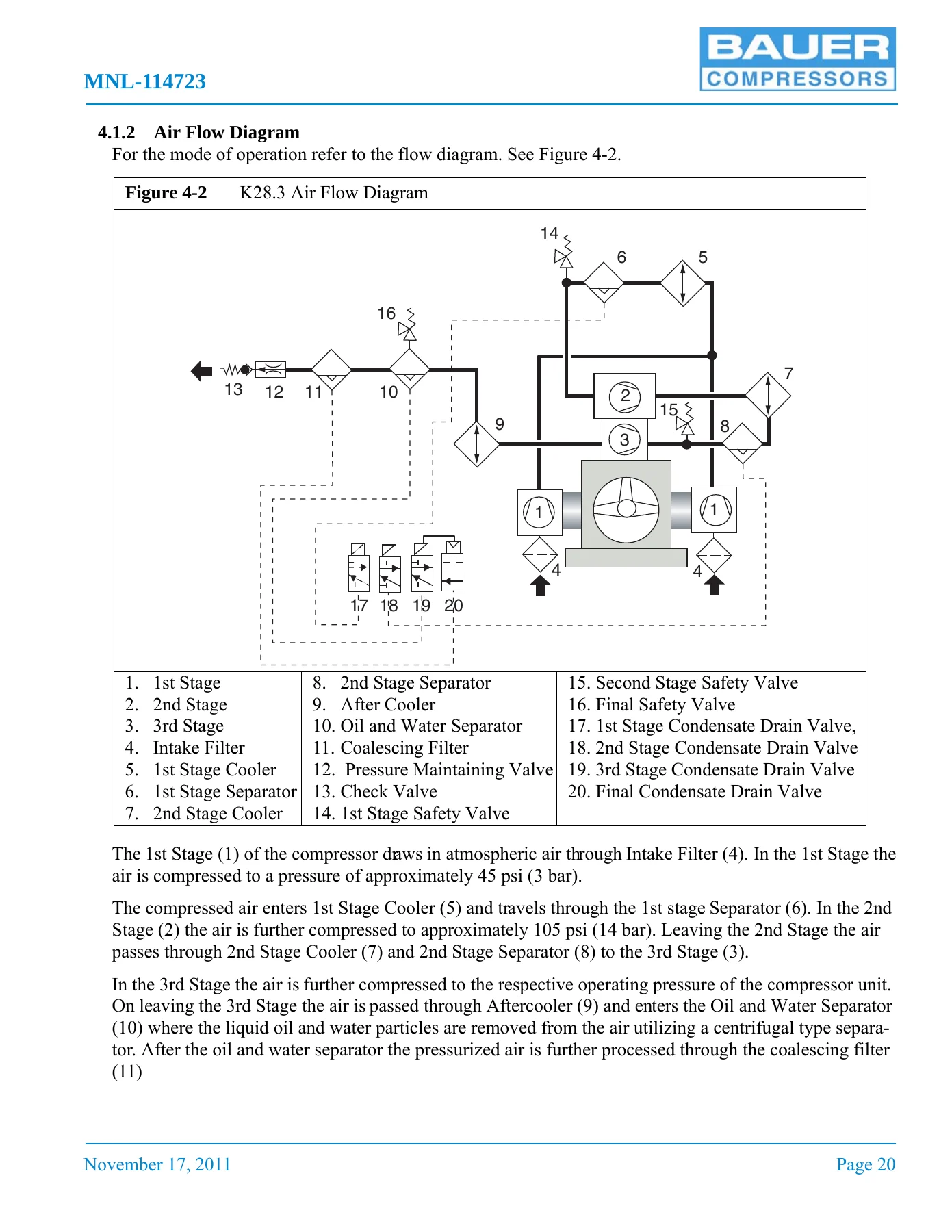
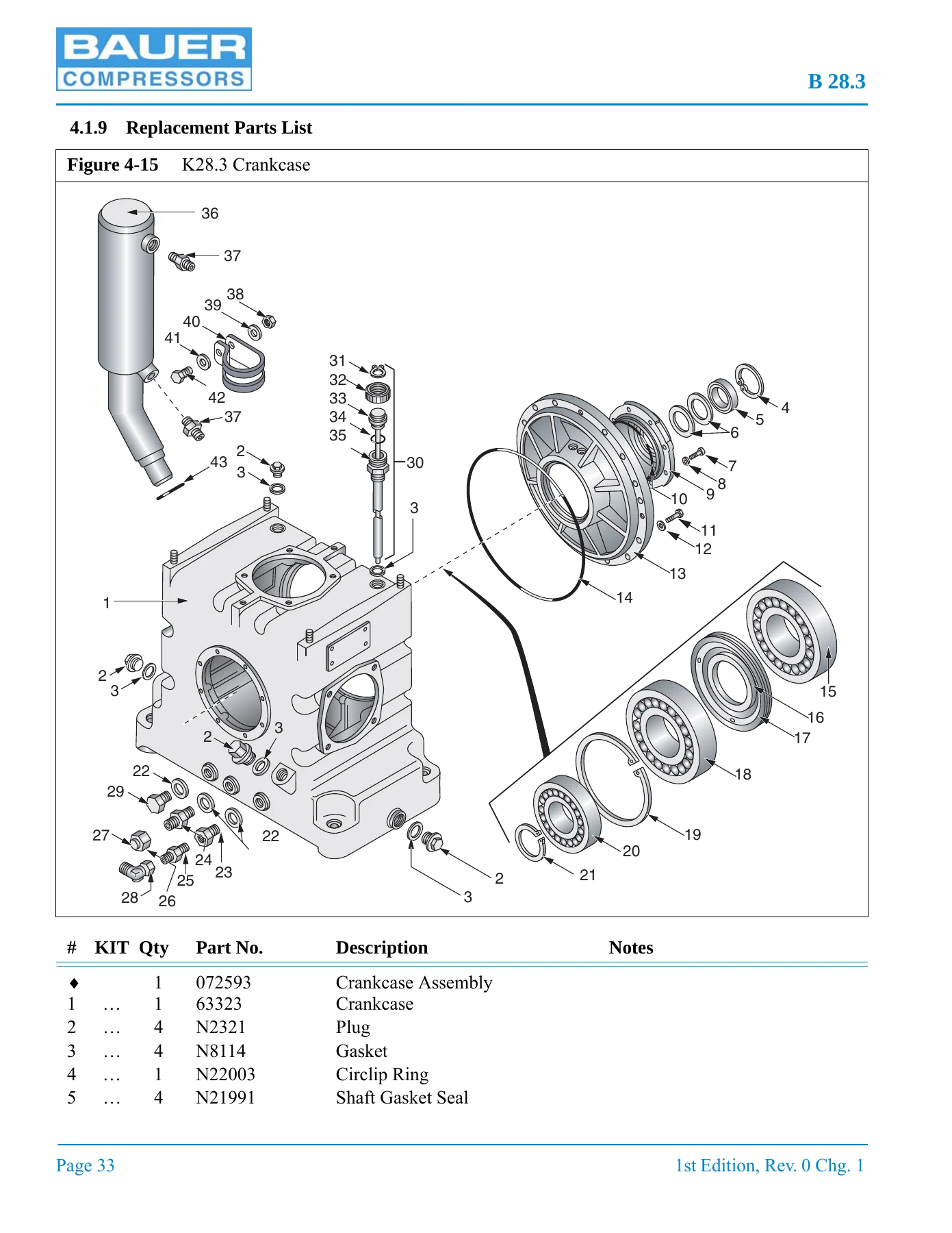
Read as a whole, this manual gives a technician a complete working picture of the B 28.3. The air flow diagram traces the medium from the intake filter through the two horizontal 1st stage cylinders, the stepped 2nd/3rd stage cylinder, the intercoolers and separators, the aftercooler, the oil and water separator, the coalescing filter, the pressure maintaining valve and the check valve to the outlet. The lubrication chapter shows how the oil pump, driven off the crankshaft through pinion gears, draws from the sump through the strainer, pushes through the full-flow cartridge filter and feeds the injection pipe. The valve chapters break down cap nuts, studs, gaskets, valve covers, O-rings, valve caps, valve gaskets and both suction and pressure valves for each stage, with separate removal and installation procedures. The parts lists go deeper still, with exploded illustrations of the crankcase, driving gear, 1st stage piston and cylinder, 2nd and 3rd stage piston and cylinder, all three valve heads, flywheel, fanwheel, intake filter, oil and water separator, lubrication system, oil pump and fanwheel drive, and both halves of the cooling system.
Diagnostics and Settings That Save Real Time
The troubleshooting tables are organised by symptom rather than by component, which is how a technician actually arrives at a problem. Compressor block faults covered include no oil pressure, low oil pressure, the compressor failing to build pressure, failing to reach final pressure or delivering insufficient output, safety valves releasing between stages, running too hot, and oil residue in the delivered air — each with the likely causes and the remedy. A separate table handles the automatic condensate drain, covering drain valves that will not open, will not close, and the 4th stage drain valve failing to open.
Adjustment values are given where they matter. Oil pressure should sit at 50 psi (3.5 bar) at nominal compressor speed, with the oil pressure switch reporting a failure below 26 psi (1.8 bar). The pressure maintaining valve is set at 500 psi (34.5 bar) +/- 100 psi (7 bar), and the manual walks through loosening the locking nut, adjusting with a hex wrench, retightening, and then verifying the opening pressure on the final pressure gauge. Maximum allowable piston ring gaps are tabulated by cylinder — 0.052 in for the 1st stage, 0.036 in for both 2nd and 3rd stage bores, and 0.032 in for the smaller 3rd stage diameter. Tightening torque values run from 7 ft-lb for 1/4 in fasteners up to 141 ft-lb for 5/8 in, with 4-bolt and 6-bolt torque sequence diagrams.
Part Numbers You Can Order From
The replacement parts lists are the reason many owners keep this document on hand. Each exploded figure carries an itemised table with item number, quantity, Bauer part number, description and notes, including assembly-level part numbers marked in the Item Number column and kit replacement intervals keyed to 1,000, 2,000 and 4,000 operating hours. In addition to the compressor block and drive, there is a full ACD system parts list covering solenoid valve options for 12 VDC, 24 VDC, 24 VAC, 115 VAC, 230 VAC and 240 VAC, plus the condensate drain valves, valve seats, valve pistons, O-rings, grooved rings and manual drain valves. The condensate separator section lists the level switch, drain valve, filter, separator, flexible hose and 7 gallon condensate tank. The electrical section carries separate parts tables for 75 HP, 100 HP and 150 HP models across 208, 230, 380, 400, 415 and 460 VAC, 50 Hz and 60 Hz, listing transformer, primary fuse, soft starter, contactor, breaker and breaker latch part numbers for each combination. The unit identification plate fields — model number, block number, serial number, quantity and manufacturing date — are shown so you know exactly what to quote when ordering.
Electrical, Control and Safety Content
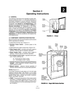
For units with the ASY-1068 XL panel and MNR-0053 Maple System operator interface, the manual documents the run screen readings, the main menu, user levels and password entry, the status screen with run time and separator count, parameters such as start pressure, shutdown pressure and separator count warning, configuration, tools, and the ACD test. Alarm descriptions cover final separator warning and shutdown cycle counts, compressor high temperature, low oil pressure, overrun timer, condensate fault and motor starter overload trip. PLC input and output tables, analog input wiring, and the HNS-0116 wiring harness layout with wire colours and pin assignments are all included. Safety content spans the danger, warning, caution and notice conventions, the warning label set used on the machine, general safety precautions for installation and service, and ventilation sizing tables for natural and forced ventilation.
Who This Manual Suits
This is a practical shop document rather than a sales brochure. It suits an operator learning the Maple System interface and the daily and weekly checks, a maintenance technician planning valve replacement at the 2,000 hour mark or an oil and filter change, and a parts person who needs to identify a gasket or a solenoid valve variant correctly on the first attempt. The scheduled maintenance forms for daily, 500, 1,000, 2,000, 3,000 hour, annual and biennial intervals, plus the record of operating hours sheets, are reproducible, so a maintenance log can be started the same day. Note that the B 28.3 is not equipped with the Bauer Purification System, and the manual states this plainly — the purification material in this document is limited accordingly.
IMAGES PREVIEW
Instant PDF Delivery
Buying this Bauer B 28.3 instruction manual and replacement parts list gives you the complete 122-page document as a downloadable PDF, delivered immediately after payment with no shipping and nothing to wait for. Open it on a laptop or tablet in the shop, print the pages you need for the job in front of you, or keep the parts list figures open beside the machine while you work. Having the correct procedures, torque values, adjustment pressures and part numbers in front of you is what separates a repair done once from a repair done three times — and with the full ACD, valve head, lubrication, cooling and electrical parts breakdowns in one file, this manual covers the B 28.3 from the intake filter to the outlet connection.


Reviews
There are no reviews yet.