
Beechcraft King Air B200 Series Wiring Diagram Manual – 2015 Reissue G PDF
Original price was: $39.95.$24.95Current price is: $24.95.
Official wiring diagrams for the King Air B200, B200C, B200GT, and B200T series, including the 2015 Reissue G update. Covers all major electrical systems, from air conditioning to lighting, for serial numbers BB-1834 and after.
Description
Complete Electrical System Documentation for the King Air B200
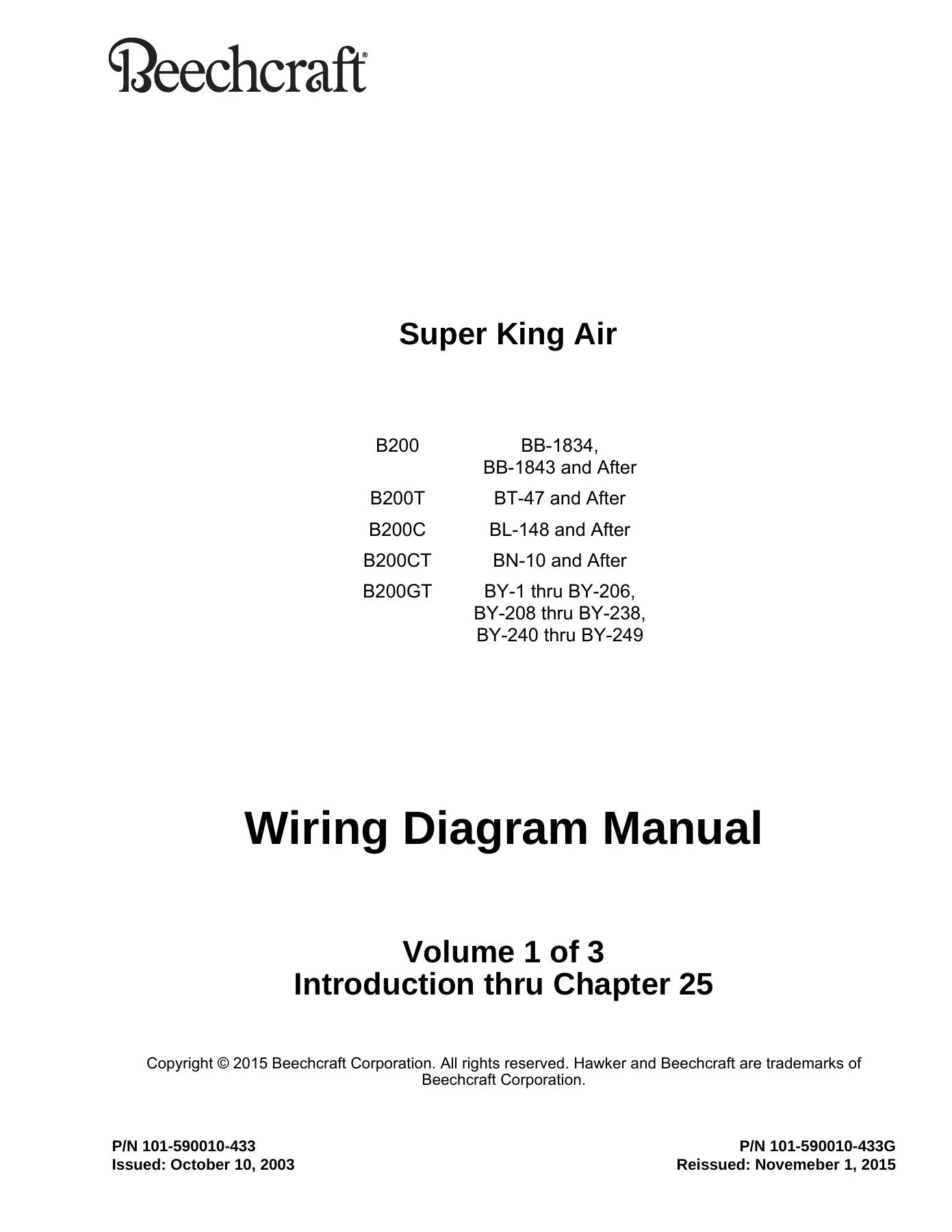
Beechcraft King Air B200 Series Wiring Diagram Manual – the definitive electrical reference for owners, maintenance technicians, and avionics shops working on the Super King Air B200, B200C, B200CT, B200GT, and B200T. This is the Reissue G edition, dated November 1, 2015, which supersedes all previous versions and includes the most up-to-date revisions for the covered serial numbers.
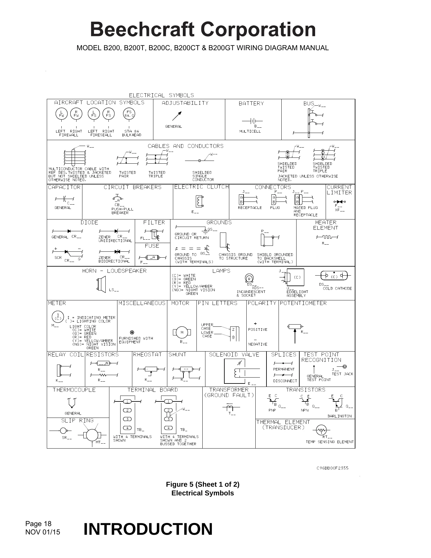
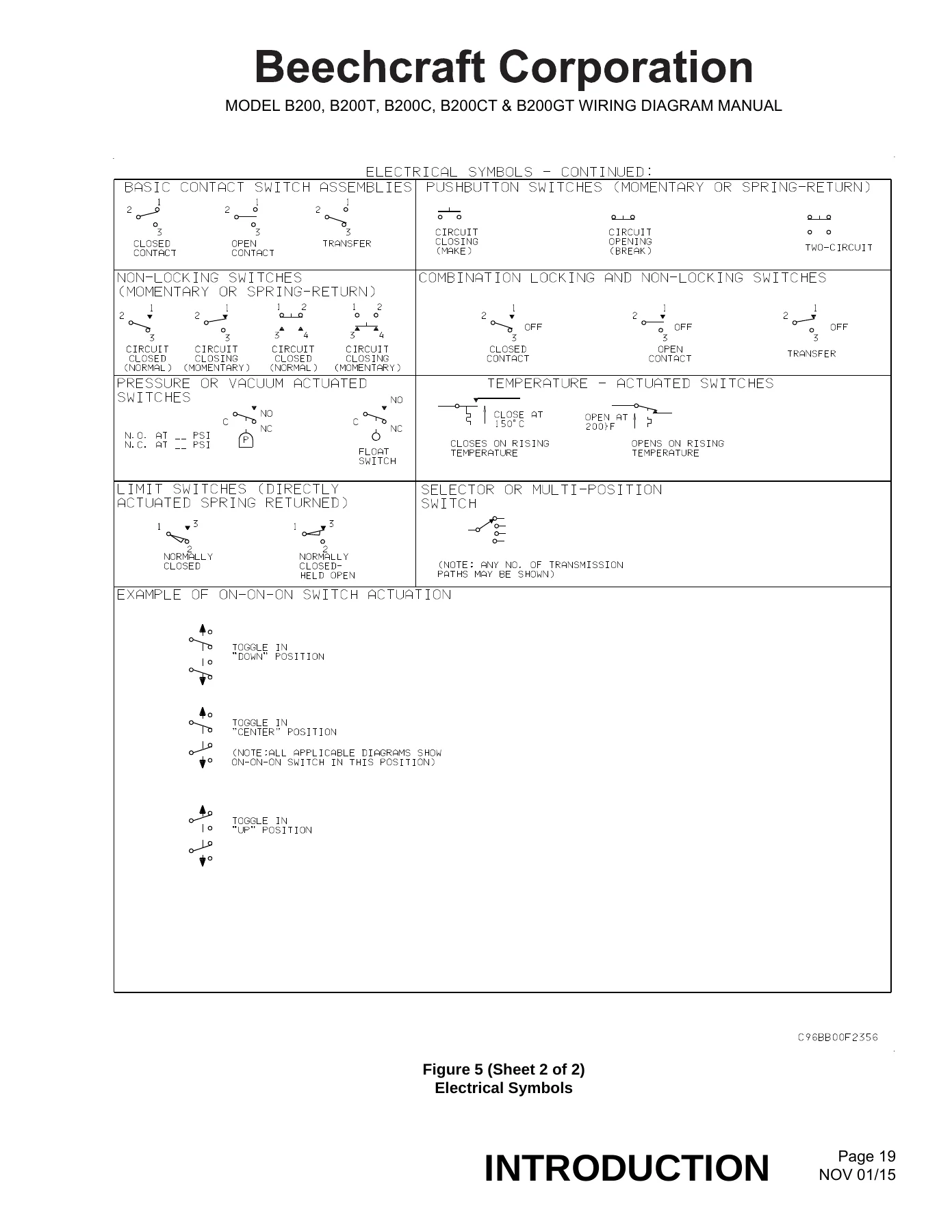
This isn’t a generic automotive manual. It is the same wiring diagram manual used by Beechcraft Corporation and authorized service centers. It provides point-to-point diagrams, equipment lists, wire run data, and circuit identification for the entire aircraft, enabling accurate troubleshooting, repair, modification, and restoration of the electrical system.
File Details
- Document Type: Wiring Diagram Manual (WDM)
- Brand / Manufacturer: Beechcraft Corporation
- Models Covered: Super King Air B200, B200C, B200CT, B200GT, B200T
- Applicable Serial Numbers: B200 BB-1834 and after, B200T BT-47 and after, B200C BL-148 and after, B200CT BN-10 and after, B200GT BY-1 through BY-206, BY-208 through BY-238, BY-240 through BY-249
- Language: English
- Total Pages: 1921+ (3 Volumes)
- File Format: PDF
- Publication Part Number: 101-590010-433
- Reissue: G (November 1, 2015)
Chapters Covered
The manual is organized according to ATA Specification 2200, making it easy to navigate. The three volumes cover the following major chapters:
- Chapter 21: Air Conditioning – Ventilation, pressurization, heating, cooling, and temperature control systems.
- Chapter 22: Auto Flight – Autopilot system wiring and components.
- Chapter 23: Communications – VHF, HF, Aircell, audio integrating, cockpit voice recorder, and ELT systems.
- Chapter 24: Electrical Power – DC generation, external power, load distribution, battery bus, main bus, and avionics buses.
- Chapter 25: Equipment/Furnishings – Control wheel clocks, chart holders, cigar lighters, and 115VAC outlets.
- Chapter 26: Fire Protection – Engine fire detection and extinguishing systems.
- Chapter 27: Flight Controls – Control wheel harnesses, rudder boost, stall warning, and flap controls.
- Chapter 28: Fuel – Fuel control panels, pump and crossfeed, quantity indicating, and warning systems.
- Chapter 30: Ice and Rain Protection – Pneumatic de-ice, engine anti-ice, pitot anti-ice, wiper control, and propeller de-ice.
- Chapter 31: Indicating/Recording Systems – Flight instruments, OAT, annunciator control, and flight display systems.
- Chapter 32: Landing Gear – Hydraulic gear control, brake de-ice, and position/warning systems.
- Chapter 33: Lights – Overhead, flight compartment, passenger, and exterior lighting systems.
- Chapter 34: Navigation – Air data systems, AHRS, GPS, DME, TCAS, EGPWS, and weather radar.
- Chapter 35: Oxygen – (Referenced in the document structure, though specific content is not detailed in the provided text).
- Chapter 38: Water/Waste – (Referenced in the document structure, though specific content is not detailed in the provided text).
- Chapter 52: Doors – (Referenced in the document structure, though specific content is not detailed in the provided text).
- Chapter 61: Propellers – (Referenced in the document structure, though specific content is not detailed in the provided text).
- Chapter 73: Engine Fuel and Controls – (Referenced in the document structure, though specific content is not detailed in the provided text).
- Chapter 74: Ignition – (Referenced in the document structure, though specific content is not detailed in the provided text).
- Chapter 76: Engine Controls – (Referenced in the document structure, though specific content is not detailed in the provided text).
- Chapter 77: Engine Indicating – (Referenced in the document structure, though specific content is not detailed in the provided text).
- Chapter 91: Charts – Extensive connector, equipment, and reference designator charts for cross-referencing.
Each chapter includes detailed wiring diagrams, equipment lists, and component identification, giving you complete visibility into the aircraft’s electrical architecture.
What You Can Do With This Manual
With the King Air B200 Wiring Diagram Manual, you can confidently perform a wide range of electrical tasks:
- Diagnose Electrical Faults: Trace circuits from power source to load, identify bad connections, and troubleshoot complex avionics issues.
- Perform Repairs: Identify wire types, connectors, and terminations to ensure correct repairs that maintain airworthiness.
- Modify or Upgrade Systems: Use the wiring diagrams to understand existing wiring and integrate new equipment safely and accurately.
- Restore or Maintain: Ensure all electrical systems, from lights to autopilot, are operating according to factory specifications.
- Cross-Reference Components: Use the included reference designator and alpha-numeric indexes to locate any part or wire quickly.
Whether you are a professional avionics technician, an A&P mechanic, or a dedicated King Air owner, this manual is an essential resource for maintaining the safety, performance, and value of your aircraft.
King Air B200 Series Wiring Diagram Manual – 2015 Reissue G. Your electrical system diagnostics and maintenance toolkit, delivered as an instant PDF download. No shipping delays, viewable on any device, printable for use in the hangar. Secure your copy today.
Reviews
There are no reviews yet.