
King Air C90A C90GT C90GTi Electrical Wiring Diagram Manual LJ-1063 and After
Original price was: $42.95.$25.95Current price is: $25.95.
Hawker Beechcraft King Air C90A, C90GT and C90GTi Electrical Wiring Diagram Manual for serials LJ-1063 and after. Reissue H, P/N 90-590024-11H, ATA point-to-point schematics, equipment lists, connector charts, zone maps, and reference-designator indexes.
Description
King Air C90A C90GT C90GTi Electrical Wiring Diagram Manual LJ-1063 and After
This file is the Hawker Beechcraft Corporation Electrical Wiring Diagram Manual for King Air models C90A, C90GT and C90GTi, effectivity LJ-1063 and After. The title-page part number is 90-590024-11, first issued December 2, 1983. The book in this download is Reissue H, P/N 90-590024-11H, dated May 1, 2013. It is written to ATA Specification 2200 and is used to identify circuits, connectors, circuit breakers, relays, lamps, switches, harness segments, and zone locations when an electrical system on these airplanes must be traced, disconnected, or rebuilt.
File Details
- Manual type: Electrical Wiring Diagram Manual (EWDM)
- Brand / models: Hawker Beechcraft King Air C90A, C90GT, C90GTi
- Effectivity: LJ-1063 and After
- Language: English
- Page count: 1327
- File format: PDF
- Document number: 90-590024-11 / 90-590024-11H
- Original issue: December 2, 1983
- Reissue H: May 1, 2013
Scope of the Wiring Book
The King Air C90A C90GT C90GTi Electrical Wiring Diagram Manual LJ-1063 and After is a point-to-point drawing set. Wire routing through structure is not shown, and mechanical parts callouts are omitted except where they are electrical. Diagrams are drawn with airplane power off, doors shut and locked, control surfaces streamlined, and weight on the landing gear unless a figure note states otherwise. Wires land on terminal boards and bus bars in the same physical order shown on the schematic.
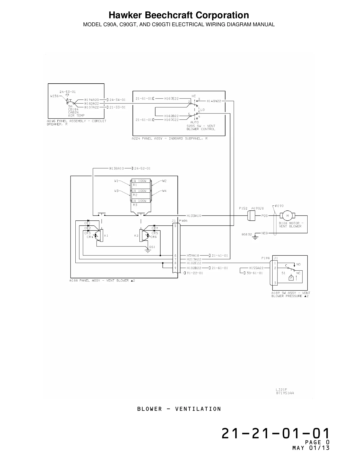
Every figure is paired with an equipment list: reference designator, part number, nomenclature, install zone, and usable-on code. When a circuit changed during production, the same unit number is issued as a new configuration. Ventilation-blower sheet 21-21-01-01 covers LJ-1063 through LJ-1534; 21-21-01-02 covers LJ-1535 and after. Battery-and-external-power, right circuit-breaker panel, flap control, landing-gear warning, and many lighting sheets follow the same pattern. UK-only, except-UK, C90SE, and JMSDF-trainer arrangements are called out on the chapter tables of contents rather than mixed into a single “typical” drawing.
The Introduction usable-on table defines codes A through D plus FE (figure effectivity) and “no code listed,” which means every airplane named on the title page. Chapter references printed on a schematic send the reader to another ATA number in this book—often Chapter 91—for a full connector parts breakdown.
How to Read ATA Numbers, Indexes, and Designators
Four numbering levels appear on the lower outside corner of each data page: chapter, section, unit, and configuration. Chapter 24 is Electrical Power. Section 50 inside that chapter is electrical load distribution. Unit 01 of that section is battery and external power. The last digit selects the serial block.
Front matter includes the Letter of Transmittal for Reissue H, the List of Effective Revisions from the 1983 original through 11B, 11C, 11D, 11E, 11F, 11G, and 11H, a Record of Revisions page, and the Introduction. The Introduction explains publication layout, abbreviation tables, class letters for reference designators, wire-code construction, approved wire-type policy, electrical symbols (two sheets), and airplane zone maps (two sheets). Printed-manual users also receive a Reference Designator Index (pages 1 through 148), Numerical Index-Alpha (pages 1 through 30), and Numerical Index-Numerical (pages 1 through 83). Those indexes point a designator or part number back to chapter-section-unit-configuration in the equipment lists.
Class letters used in this EWDM include A (assembly), AR (amplifier), B (motor, blower, pump), BS (bonding strap), BT (battery), C (capacitor), CB (circuit breaker), CP (adapter/connector), CR (diode), DS (annunciator, indicator, lamp), E (miscellaneous electrical), F (fuse/current limiter), FL (filter), G (generator), GS (ground stud), HR (heater), HT (headset), J (receptacle/jack), K (relay), L (inductor), LS (horn), M (clock, instrument, meter), MG (inverter), MK (microphone), P (plug), PS (power supply), Q (transistor), R (resistor/potentiometer), S (switch), SP (splice), T (transformer), TB (terminal board), TC (thermocouple), TP (test point), TR (transmitter), W (cable), XDS (lampholder), and XF (fuse holder). A detail part drawn inside an assembly outline carries the parent designator first: TB1 on fuel-control panel A124 is listed as A124TB1.
Chapters Covered
- Introduction — layout, ATA numbering, abbreviations, class letters, usable-on codes, wire codes, delta notes, electrical symbols, zone locations
- Reference Designator Index; Numerical Index-Alpha; Numerical Index-Numerical
- Chapter 21 Environmental / Air Conditioning — distribution; ventilation blower; cabin pressurization control; bleed-air pressurization valves; ambient-air pressurization control; electric heat; cabin cooling; cabin temperature control
- Chapter 23 Communications — speech communication; pilot and copilot microphone switches
- Chapter 24 Electrical Power — overhead meter panel; left inboard subpanel; AC generation and inverters; inverter harness W300; left and right DC generation; generator overtemperature (UK only); bus-tie control; battery and external power; left and right DC power panels; right circuit-breaker panel including C90SE single-avionics and dual-avionics layouts; center bus; triple-fed bus; avionics buses
- Chapter 25 Equipment / Furnishings — control-wheel clocks (standard and optional); optional control-wheel chartholders; optional cabin cigarette lighter; optional buffet/galley refreshment bar
- Chapter 26 Fire Protection — left and right engine fire detection (optional and UK-only); optional engine fire extinguishing
- Chapter 27 Flight Controls — pilot and copilot control-wheel harnesses with and without pitch-trim switch; rudder boost including C90SE; stall-warning indicator; elevator trim control; electrical flap control; flap-position indicator
- Chapter 28 Fuel — fuel control panel (except-UK and UK-only configurations); wing fuel vent heater; fuel boost pump and crossfeed; fuel transfer; left and right fuel quantity
- Chapter 30 Ice and Rain Protection — pneumatic deice control; left and right engine anti-ice; pitot anti-ice including kit 90-3118-1; windshield anti-ice; windshield wiper control; propeller deice control
- Chapter 31 Indicating / Recording Systems — flight hour meter; digital outside air temperature including C90SE; annunciator control; annunciator warning (except-UK and UK-only)
- Chapter 32 Landing Gear — hydraulic landing-gear control; hydraulic position indication; hydraulic landing-gear warning
- Chapter 33 Lights — overhead control panel; indirect instrument lights; engine-instrument and flight-instrument lights; gyro and avionics panel lights; electroluminescent power supply; outside-air-temperature light; overhead, subpanel and pedestal lighting; control-panel lighting; side-panel lighting; passenger, cargo/service, exterior and ice-light circuits as listed in the chapter
- Chapter 34 Navigation / Pitot Static — pilot turn-and-slip indicator; copilot turn-and-slip indicator
- Chapter 61 Propellers — propeller governor test; left and right autofeather; propeller synchrophaser; propeller balancing; propeller tachometer; propeller reversing
- Chapter 73 Engine Fuel and Control — engine fuel-control heater; fuel-flow indicating
- Chapter 74 Ignition — left and right start auto-ignition and fuel-control purge valve
- Chapter 76 Engine Controls — emergency fuel shutdown
- Chapter 77 Engine Indicating — turbine tachometer power; torquemeter power; interstage turbine temperature
- Chapter 79 Oil — oil-pressure indicating; oil-temperature indicating; chip detector including JMSDF trainer sheets; engine oil-pressure warning (UK and except-UK)
- Chapter 91 Charts and Wiring Diagrams — No. 1 and No. 2 left and right firewall connectors; left and right landing-gear safety-switch connectors; nose disconnect; cabin and subpanel grounding connectors; relay-panel connectors and related pin charts
Across those chapters the King Air C90A C90GT C90GTi Electrical Wiring Diagram Manual LJ-1063 and After shows how generator, battery, external-power, inverter, center-bus, triple-fed-bus and avionics-bus power reach blowers, pressurization valves, electric heat, cooling, pumps, flap motors, landing-gear valves, lights, ignition, propeller governors, fuel-quantity probes, ITT circuits, oil sensors and warning lamps. The equipment list beside each schematic is the source for the procurable breaker, relay, connector, lamp or transmitter part number. Chapter 91 closes the loop when a firewall, nose or cabin disconnect must be opened and rebuilt pin for pin.
Wire Codes, Zones and Drawing Notes
Wire identification follows the military-style code drawn in Introduction Figure 2: circuit-function letter, wire number, segment letter, AWG size, and optional suffixes. Circuit-function letters used in this EWDM are C (control surfaces), D (miscellaneous instruments), E (engine instruments), F (flight instruments), G (landing gear), H (heating, ventilating and deicing), J (ignition), K (engine control), L (lighting), M (miscellaneous electrical), P (DC power), Q (fuel and oil), V (DC power for A/C systems), W (warning/emergency) and X (AC power). Suffix N marks a ground-return conductor. Phase letters A, B or C mark three-phase AC. Suffix V marks an ungrounded single-phase conductor. Thermocouple suffixes printed in the book are CHROM, CONST, ALME, COP, IRON and ALUM. Identification is required within three inches of each junction; wires shorter than six inches need no imprint. Where an imprint cannot be applied, a non-metallic sleeve carries the code. Replacement wire must be the same type and size; if type cannot be determined the Introduction directs the user to Hawker Beechcraft Customer Support.
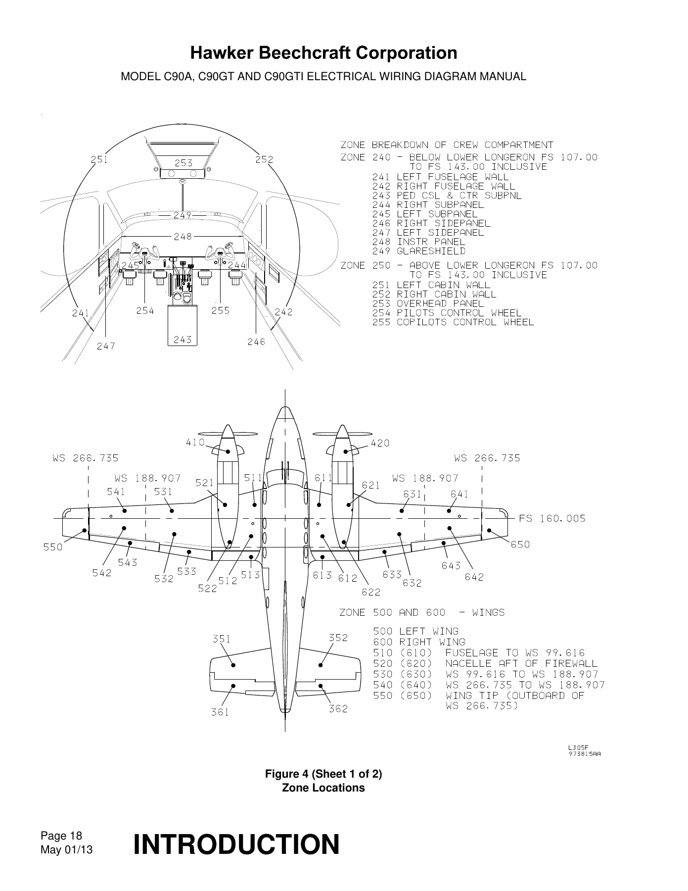
Zone maps (Introduction Figure 4, two sheets) number the airframe from 100 through 800 so the equipment-list Zone column can be read against structure. Crew-compartment zones 240 and 250 split the cockpit below and above the lower longeron. Wing zones 500 and 600 run from the fuselage outboard to the tip. Empennage is 300, powerplants 400, doors 800, gear wells 700. Fuselage-station and wing-station callouts are printed on the drawings. An underlined pin letter on a chart is lowercase. All connectors on the charts are viewed from the back of the connector.
Delta notes used on figures cover twisted-pair lay (one twist per length equal to seven outside diameters), complete assembly-level reference designators, duplicated left/right harness numbers, optional equipment that is capped and stowed when not installed, and shielding-pigtail practice for 131681AA22-0 (131681AE20-0 on engine harnesses). Notes 7, 8 and 9 send the reader to the separate Model C90GTi Avionics Wiring Diagram Manual, P/N 90-590024-175, for detailed avionics interconnects. That avionics manual is not part of this PDF.
Publications This EWDM Points To
The Introduction states that the owner or operator must use the latest revision of the publications referenced here. Titles listed as supplements are the Model C90 Series and E90 Illustrated Parts Catalog P/N 90-590012-17; Model C90GTi Illustrated Parts Catalog P/N 90-590024-173; King Air Series Component Maintenance Manual P/N 101-590097-13; King Air 90 Series Maintenance Manual P/N 90-590012-13; Model C90GTi Avionics Wiring Diagram Manual P/N 90-590024-175; King Air and Airliner Series Printed Circuit Board Manual P/N 98-39117; and King Air Structural Inspection and Repair Manual P/N 98-39006. Service bulletins issued by Hawker Beechcraft Corporation are described as an integral part of the information in this book. Those other manuals are not included in this download.
The Introduction also warns that only parts obtained from sources approved by Hawker Beechcraft Corporation are to be used, and that any maintenance that disconnects flight-control cables, plumbing, electrical connectors or wiring requires identification of each side before separation and a functional check after reconnection. Optional equipment is not always separated from standard equipment in the drawings; some harnesses are installed in every airplane and capped and stowed when the option is absent from the work order.
Work This Manual Supports
Keep the King Air C90A C90GT C90GTi Electrical Wiring Diagram Manual LJ-1063 and After at the bench when a bus will not pick up, a flap motor is dead, a firewall connector must be rebuilt, a pressurization-control sheet has to match the data plate, or a reference designator has to become a part number before an order is placed. Configuration letters and pin charts matter on these airframes because left/right harnesses, UK versus except-UK panels, C90SE avionics layouts and later serial lighting packages are not interchangeable by appearance. After payment the PDF is delivered immediately — no shipping wait — for viewing on any device and printing the sheets needed for the job.
Reviews
There are no reviews yet.