★ TRUSTED BY 321,897+ PROFESSIONALS WORLDWIDE
🏒
Trusted Business
Verified & Licensed
πŸ›‘οΈ
Virus Free Files
100% Safe Downloads
πŸ”’
Secure Payment
SSL Protected
⚑
Instant Delivery
Available Immediately
Sale!

Beechjet 400A / Hawker 400XP (Model 400A) FAA Approved Airplane Flight Manual – PDF

Original price was: $39.95.Current price is: $23.95.

Complete 1002-page FAA Approved Airplane Flight Manual for the Beechjet 400A and Hawker 400XP (Model 400A), P/N 128-590001-167B, reissued June 23, 2011. Covers limitations, emergency and abnormal procedures, normal procedures, performance, weight & balance, and all supplements for the JT15D-5 / JT15D-5R powered 400A.

⚑
Instant PDF Download
Available immediately
πŸ’Ύ
Save to Your Device
Download & keep forever
πŸ›‘οΈ
Antivirus Scanned
100% virus-free
🌍
Trusted Worldwide
175,000+ customers

Description

Beechjet 400A / Hawker 400XP (Model 400A) FAA Approved Airplane Flight Manual – PDF

The Beechjet 400A / Hawker 400XP (Model 400A) FAA Approved Airplane Flight Manual is the complete pilot-side operational manual for the Hawker Beechcraft 400A series, issued as P/N 128-590001-167B with a reissue date of June 23, 2011. This PDF combines the current AFM text with its Log of Temporary Changes, Log of Revisions, Log of Supplements, and the manufacturer-approved supplement pack into a single reference package covering the Beechjet 400A and Hawker 400XP by serial number.

File Details

  • Manual Type: FAA Approved Airplane Flight Manual (AFM) with supplements
  • Brand / Publisher: Hawker Beechcraft Corporation
  • Models Covered: Beechjet 400A, Hawker 400XP (Model 400A)
  • Engines Covered: Pratt & Whitney Canada JT15D-5, JT15D-5R
  • Document Number: P/N 128-590001-167B
  • Reissue Date: June 23, 2011
  • Language: English
  • Page Count: 1002 pages
  • File Format: PDF

Chapters Covered

  • Introduction, Certification Basis, Notations, Use of the Flight Manual, Revising the Flight Manual, Kit List
  • Section 1 – General
  • Section 2 – Operating Limitations (Airspeed Limitations, Instrument Markings for RK-1 thru RK-97 and RK-98 and After, Power Plant, Engine Limits, Thrust Reverser Limits, Starter/Generator, External Power Assisted Start, Battery Start, Generator Assisted Start, In-Flight Operation, Oil Specification, Weight Limits, Structural Limitations, Take-off Weight, Landing Weight, Fuel System, Approved Engine Fuels & Additives, Fuel Temperature Limitations, Fuel Management, Hydraulic System, Cabin Pressurization, Maneuvering Load Factors, Occupancy Limits, Avionic System, Autopilot, EFIS, TCAS, Flight Management System, Kinds of Operations, All Operations, Take-off and Landing Operations, En Route Operations)
  • Section 3 – Emergency Procedures (Engine Failure During Takeoff Below/Above V1, Engine Fire, Engine Fire Detector Failure, Engine Shutdown or Failure In Flight, Dual Engine Flameout, Engine Failure In Landing Configuration, Engine Failure Autopilot Coupled, Low Oil Pressure, Low Fuel Pressure, Inadvertent Thrust Reverser Deployment On Takeoff and In Flight, Main Landing Gear Ground Safety Switch Failure, Inadvertent Overspeed, Emergency Landing, Loss of Airspeed Indication, Ditching Procedures, Fire and Smoke Protection, Electrical Fire or Smoke, Environmental System Smoke or Odor, Smoke Removal, Cabin Decompression, Oxygen Duration, Emergency Descent, Overpressurization, Windshield Overheat, Wing Anti-Ice Overheat, Horizontal Stab Ice Protection Failure, Loss of Both Generators, Battery Overheat, Trim Systems Malfunctions, Pitch/Roll/Rudder Trim Runaway, Power Brake Failure, Autopilot Disengagement, Autopilot Trim Fail, Autopilot Overspeed Recovery, Flight Director Malfunctions, Maximum Altitude Losses, Air Data Computer Failure, Electronic Flight Display Messages, PFD/MFD/ND/CDU Messages, Master Annunciator Panels)
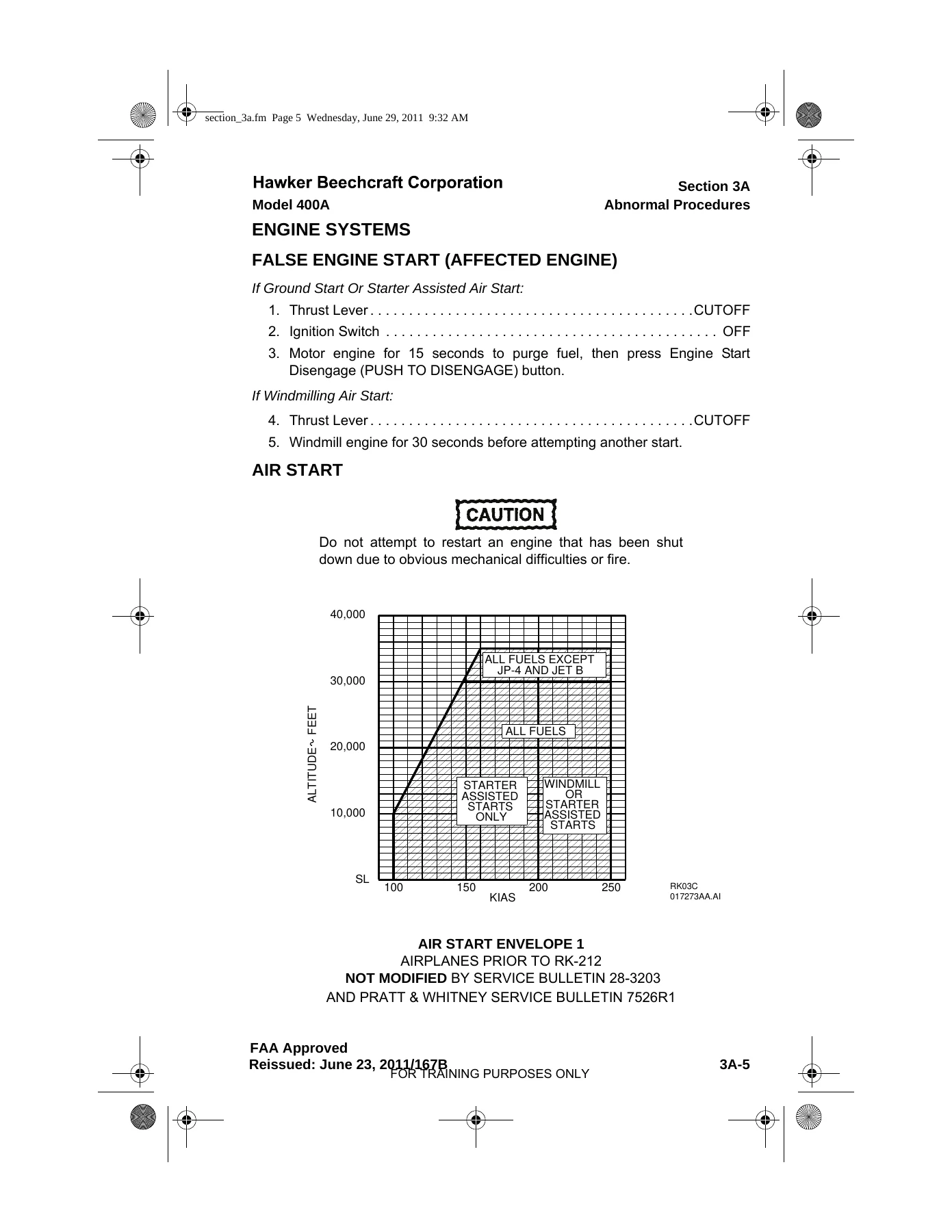
  • Section 3A – Abnormal Procedures (False Engine Start, Air Start Envelope 1 and 2, Pre-Start Check, Starter Assisted Start, Windmilling Start, Post-Start Check, Thrust Reverser Arm and Unlock Annunciators, High Oil Temperatures, Oil Filter Bypass, Engine Anti-Ice System Inoperative, EFC Failure, One Engine Inoperative Approach and Landing, Single Engine Reversing, One Engine Inoperative with a Reverser Deployed, Approach Climb, No-Flap Approach and Landing, Flaps 10Β° Approach and Landing, Landing with Ice Accumulation, Side Window Landing, Inadvertent Icing Encounter, Ice Detector Fail, Turbulent Air Penetration, Stall Warning Failure, Wing Tank Overpressure, Jet Pump Failure, Low Fuel Transfer Pressure, Low Fuel Quantity, Low Engine Fuel Feed Tank Quantity, Fuel Filter Bypass, Air Conditioning Overpressure/Overtemperature, Refrigeration Air Conditioning Malfunction, Bleed Air Duct Failure, Cabin Air Temperature, Defog Overtemperature, Vacuum Source Failure, Cabin or Aft Fuselage Door Unlocked, Windshield Cracked, Battery Feeder Failure, Emergency Bus Feeder Failure, Bus Feeder Failure, Battery Cutoff, Single Generator Failure, Inverter Failure, Pitot Heat Failure, Rudder Boost Failure, Take-Off Mistrim, Main/Aft Flap Asymmetry, Elevator/Rudder Control Binding, Jammed Stabilizer/Elevator/Spoiler/Rudder, Low Hydraulic Fluid Quantity, Low/High Hydraulic Pressure, Landing Gear Handle Lock, Landing Gear Not Down and Locked, Alternate Gear Extension, Anti-Skid Failure, Yaw Damp Failure, Single/Dual RTU Failure, Radio Remote Tuning Disabled, Electronic Flight Display Messages)
  • Section 4 – Normal Procedures (Preflight Inspection, Cockpit/Cabin Inspection, Exterior Inspection, Cabin Door, Left/Right Nose, Right/Left Wing, Right/Left Nacelle, Empennage, Aft Baggage Compartment, Before Starting Engines, Starting Engines, Before Taxi, Taxi, Anti/Deice System Preflight Check, Engine and Wing Anti-Ice Checks, Horizontal Stabilizer Deice System Check, Before Takeoff, Takeoff, After Takeoff, Anti/Deice Systems In-Flight Operation, Climb FL180, Cruise, Fuel Management Procedures, Descent, Approach, Before Landing, Landing, Balked Landing, After Landing, Shutdown, Turnaround, Autopilot and Flight Director Preflight Checks and In-Flight Operation, Vertical Synchronization, Pitch/Turn Knob, Turbulence Mode, Autopilot Transfer, Yaw Damp Operation, Automatic Trim Operation, Mode Selection, Go-Around, Heading, Navigation, Approach, Half Bank, Vertical Speed, Level Change, Speed Hold, VNAV, Altitude Hold, FD Off, Flight Management System Programming, In-Flight Operation, TCAS Preflight Checks, Ground Operation, In-Flight Operation)
  • Section 5 – Performance (Performance Limitations, Acoustic Levels, Supplemental Acoustic Levels, Operational Factors, Flight Test Performance Conditions, Definitions, General Information on Using Graphs, Pressure Altitude, Procedures for Use of Take-off Performance Charts, Take-off Weight Analysis, Take-off Flap Setting Selection, ECS OFF Takeoff, Icing-Conditions Takeoff, Take-off Flight Path Profile, Obstacle Clearance Analysis, Example Close-In and Distant Obstacle Clearance, Take-off Speeds, Approach and Landing Performance, Landing Weight Analysis, ECS OFF Approach/Landing, Icing-Conditions Approach/Landing, Unfactored and Factored Landing Distance, Take-off Speeds and Field Length Tables and Correction Graphs for Flaps 0Β°, 10Β° and 20Β°, Net Take-off Flight Path Segments, Enroute Net Climb Gradient, Maximum Landing Weight Charts, Landing Brake Energy, Accelerate-Stop Brake Energy, Turnaround Time)
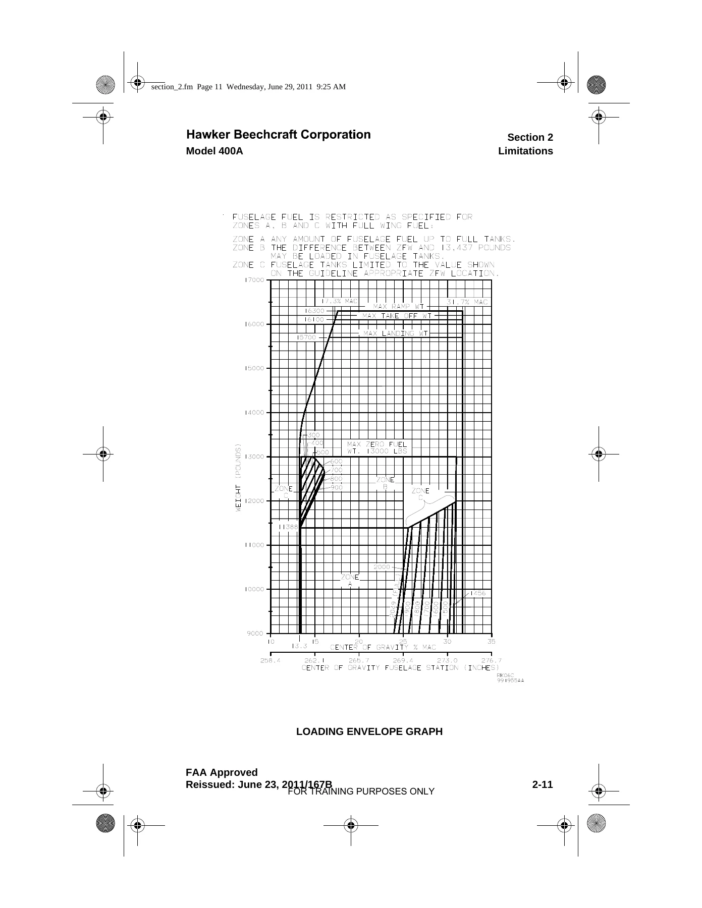
  • Section 6 – Weight & Balance / Equipment List (Basic Empty Weight and Balance, Sample Loading, Weight and Balance Terminology, Basic Empty Weight and Balance Form, Empty Weight and Balance Record, Dimensional Data, Airplane Loading Form Instructions, Weight and Balance Loading Form, Loading Envelope Table and Graph, Zero Fuel Weight Table, Usable Fuel Moment Table, Payload Data for RK-1 thru RK-97 / RK-98, RK-110 thru RK-379 / RK-380 and After, Cabin Arrangement Diagrams, Unusable Fuel, Engine Oil, Personnel Movement, Weighing Instructions)
  • Section 7 – Supplements (Log of Supplements, HF-9000, Category II Operation, German Registered Airplanes, FDR, Mod Drawing 004359, AMS-5000 with and without FMS-97, WG ICE TEMP LO Annunciator, Austrian Registered Airplanes, Increased Gross Take-Off Weight to 16,300 Pounds, Optional Galley Configurations, JAR-OPS 1 Wet/Contaminated Runway Operation, Mode S Enhanced Surveillance, Honeywell AFIS, EGPWS with RAAS, Collins GPS-4000S, CDL, TDR-94D ADS-B Out)
  • Manufacturer Approved Supplements (Deicing/Anti-Icing Fluids Type I, II, III, IV; Wet or Contaminated Runways; Metric Conversion Factors; Standard Instrument Departure Charts)

Complete PDF Bookmark Tree

Complete Bookmarks

The complete bookmarks in the β€œBeechjet 400A / Hawker 400XP (Model 400A) FAA Approved Airplane Flight Manual – PDF” are as follows:

BEECHJET 400A / HAWKER 400XP AIRPLANE FLIGHT MANUAL P/N 128-590001-167p. 1
TITLE PAGEp. 3
EXPORT STATEMENTp. 4
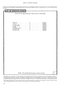
LIST OF EFFECTIVE PAGESp. 5
LOG OF TEMPORARY CHANGESp. 6
LOG OF REVISIONSp. 16
SECTION 1 – GENERALp. 36
Introductionp. 37
Certification Basisp. 37
Notationsp. 37
Section 2 – Operating Limitationsp. 37
Section 3 – Emergency Proceduresp. 37
Section 3A – Abnormal Proceduresp. 38
Section 4 – Normal Proceduresp. 38
Section 5 – Performancep. 38
Section 6 – Weight & Balance/Equip Listp. 38
Section 7 – Supplementsp. 38
Use of the Flight Manualp. 38
Revising the Flight Manualp. 39
Supplier-Issued STC Supplementsp. 40
Kit Listp. 40
SECTION 2 – LIMITATIONSp. 41
Airspeed Limitationsp. 43
Instrument Markingsp. 45
RK-1 thru RK-97p. 45
RK-98 and Afterp. 46
Power Plantp. 47
Number of Enginesp. 47
Engine Manufacturerp. 47
Engine Model Numberp. 47
Engine Limitsp. 47
Footnotesp. 47
Thrust Reverser Limitsp. 48
Starter/Generatorp. 48
External Power Assisted Start (Starter Limitation)p. 48
Battery Start (Battery Limitation)p. 49
RK-1 thru RK-97; Nickel-Cadmium Batteryp. 49
RK-98 and After; Lead Acid Batteryp. 49
Generator Assisted Startp. 49
In-Flight Operation (Maximum)p. 49
Oil Specificationp. 49
Weight Limitsp. 50
Structural Limitationsp. 50
Take-off Weightp. 50
Landing Weightp. 52
Fuel Systemp. 52
Fuel Limitsp. 52
Approved Engine FuelsRK-1 thru RK-507 NOT MODIFIED by Kit 128-9008p. 52
RK-106 thru RK-507 MODIFIED by Kit 128-9008and RK-508 and Afterp. 52
Approved Fuel Additivesp. 52
RK-1 thru RK-507 NOT MODIFIED by Kit 128-9008and Kit 128-9009p. 52
RK-508 thru RK-529 NOT MODIFIED by Kit 128-9009p. 52
RK-106 thru RK-507 MODIFIED by Kit 128-9008and Kit 128-9009p. 53
RK-508 thru RK-529 MODIFIED by Kit 128-9009and RK-530 and Afterp. 53
Fuel Temperature Limitationsp. 53
Fuel Managementp. 53
Hydraulic Systemp. 53
Cabin Pressurization Systemp. 53
Maneuvering Load Factorsp. 53
Occupancy Limitsp. 53
Avionic Systemp. 54
Generalp. 54
Autopilotp. 54
EFISp. 55
TCAS (If Installed)p. 55
Flight Management Systemp. 55
Kinds of Operationsp. 57
All Operationsp. 57
Take-off and Landing Operationsp. 59
En Route Operationsp. 60
SECTION 3 – EMERGENCY PROCEDURESp. 61
Engine Systemsp. 63
Engine Failure During Takeoff (Below V1 – Takeoff Aborted)p. 63
Engine Failure During Takeoff (Above V1 – Takeoff Continued)p. 63
Engine Firep. 64
Engine Fire Detector Failure (L or R FIRE DET FAILAnnunciator Illuminated)p. 65
Engine Shutdown or Failure In Flightp. 65
Dual Engine Flameoutp. 66
Engine Failure In Landing Configurationp. 66
Engine Failure (Autopilot Coupled)p. 67
Low Oil Pressurep. 67
Low Fuel Pressure (L or R FUEL PRESS LO Annunciator Illuminated)p. 67
Inadvertent Thrust Reverser Deployment DuringTakeoff (Below V1 – Takeoff Aborted)p. 68
Inadvertent Thrust Reverser Deployment DuringTakeoff (Above V1 – Takeoff Continued)p. 68
Inadvertent Thrust Reverser DeploymentIn Flight (UNLOCK/DEPLOY Annunciator Illuminated)p. 69
Main Landing Gear Ground Safety Switch Failure on Takeoffp. 69
Operationsp. 70
Inadvertent Overspeedp. 70
Emergency Landingp. 70
Loss of Airspeed Indicationp. 70
Ditching Proceduresp. 72
Fire and Smoke Protectionp. 73
Electrical Fire or Smokep. 74
Environmental System Smoke or Odorp. 76
Smoke Removalp. 77
Environmental Systemsp. 77
Cabin Decompression (CABIN PRESSURE LO AnnunciatorIlluminated)p. 77
Oxygen Durationp. 78
Emergency Descentp. 79
Overpressurization (CABIN PRESSURE HI Annunciator Illuminated)p. 80
Windshield Overheat (WSHLD OV HT AnnunciatorIlluminated)p. 80
Wing Anti-Ice Overheat (WING OV HT AnnunciatorIlluminated)p. 80
Horizontal Stab Ice Protection System Failure (H STAB ICE FAILAnnunciator Illuminated)p. 81
Electrical Systemsp. 81
Loss of Both Generators (L and R GEN OFFAnnunciators Illuminated)p. 81
Battery Overheatp. 84
Flight Control Systemsp. 85
Trim Systems Malfunctionsp. 85
Pitch Trim Runaway or Failurep. 85
Roll Trim Runaway or Failurep. 85
Rudder Trim Runaway or Failurep. 86
Wheel Brake Systemsp. 86
Power Brake Failurep. 86
Avionic Systemsp. 87
Autopilotp. 87
Autopilot Disengagementp. 87
Autopilot Trim Fail (AP PITCH TRM FAIL or AP ROLL TRM FAILAnnunciator Illuminated)p. 87
Autopilot Overspeed Recoveryp. 88
Flight Director Malfunctionsp. 88
Maximum Altitude Lossesp. 88
Air Data Computer Failurep. 88
Electronic Flight Display Messagesp. 89
Primary Flight Displays (PFD)p. 89
Multifunction Display (MFD)and Navigation Display (ND)p. 91
Control Display Units (CDU)p. 91
Master Annunciator Panel (Red Annunciators)RK-1 thru RK-97p. 92
Master Annunciator Panel (Red Annunciators)RK-98 and Afterp. 93
SECTION 3A – ABNORMAL PROCEDURESp. 94
Engine Systemsp. 98
False Engine Start (Affected Engine)p. 98
Air Startp. 98
Pre-Start Check (Inoperative Engine)p. 99
Starter Assisted Start (Inoperative Engine)p. 100
Windmilling Start (Inoperative Engine)p. 100
Post-Start Check (Affected Engine)p. 100
Thrust Reverser Arm Annunciator Illuminated In Flightp. 100
Thrust Reverser Unlock Annunciator Illuminated In Flightp. 101
High Oil Temperaturesp. 101
Oil Filter Bypass (L or R O FLTR BYPASSAnnunciator Illuminated)p. 101
Engine Anti-Ice System Inoperative(L or R ENG ICE TEMP LO Annunciator Illuminated)p. 102
EFC Failure (L or R ENG EFC OFF Annunciator Illuminated)p. 102
Operationsp. 102
One Engine Inoperative Approach and Landingp. 102
Single Engine Reversingp. 103
One Engine Inoperative Approach and Landingwith a Reverser Deployedp. 103
Approach Climb (One Engine Go-Around)p. 104
No-Flap Approach and Landingp. 104
Flaps 10Β° Approach and Landingp. 105
Landing with Ice Accumulation on the Wingsp. 106
Side Window Landingp. 107
Inadvertent Icing Encounterp. 107
Ice Detector Fail (ICE DET FAIL Annunciator Illuminated)p. 108
Turbulent Air Penetrationp. 108
Stall Warning Shaker/Supplemental Stall RecognitionSystem Failure (L or R STALL WRN FAILAnnunciator Illuminated)p. 108
Fuel Systemsp. 109
Wing Tank Overpressure (L or R WG TK OV PRESS AnnunciatorIlluminated)p. 109
Jet Pump Failurep. 109
Low Fuel Transfer Pressure (L or R F XFR PRESS LO AnnunciatorIlluminated)p. 109
Failure of Aft Fuselage Fuel to Transferp. 110
Low Fuel Quantity (L or R FUEL LEVEL LOAnnunciator Illuminated)p. 110
Low Engine Fuel Feed Tank Quantity (L or R FUEL FEEDAnnunciator Illuminated)p. 110
Fuel Filter Bypass (L or R F FLTR BYPASSAnnunciator Illuminated)p. 111
Environmental Systemsp. 111
Air Conditioning System Overpressure or Overtemperature(AIR COND FAIL Annunciator Illuminated)p. 111
Refrigeration Air Conditioning Malfunctionp. 111
Bleed Air Duct Failure (BL AIR DCT FAIL Annunciator Illuminated)p. 111
Cabin Air Temperature (CABIN AIR OV HT Annunciator Illuminated)p. 112
Defog Overtemperature (DEFOG AIR OV HT Annunciator Illuminated). .3A-20Vacuum Source Failurep. 113
Vacuum Source Failurep. 113
Cabin or Aft Fuselage Door Unlocked (DOOR UNLOCK AnnunciatorIlluminated)p. 113
Windshield Crackedp. 113
Outer Glass Plyp. 114
Either Acrylic Structural Plyp. 114
Both Acrylic Structural Pliesp. 114
Electrical Systemsp. 115
Battery Feeder Failure (BATT FDR FAIL Light Illuminated)(Overhead Panel)p. 115
Emergency Bus Feeder Failure (EMER BUS FDR FAIL AnnunciatorIlluminated)p. 115
Bus Feeder Failure (L or R BUS FDR FAIL Annunciator Illuminated). . . 3A-23Battery Cutoff (BATT CUT OFF Annunciator Illuminated)p. 116
Battery Cutoff (Batt Cut Off Annunciator Illuminated)p. 116
Single Generator Failure (GEN OFF Annunciator Illuminated)p. 116
Inverter Failure (INV 1 FAIL or INV 2 FAIL Annunciator Illuminated)p. 116
Pitot Heat Failure (PITOT HT OFF Annunciator Illuminated)p. 117
Flight Control Systemsp. 117
Speed Brakes Remain Extended (SPD BRAKE EXT AnnunciatorIlluminated)p. 117
Rudder Boost Failure (RDR BST FAIL Annunciator Illuminated)p. 117
Take-Off Mistrim (Horn Sounds)p. 118
Main Flap Asymmetry (FLAP ASYM Annunciator Illuminated)p. 118
Aft Flap Asymmetry (FLAP ASYM Annunciator Not Illuminated)p. 119
Elevator/Rudder Control System Bindingp. 119
Jammed Stabilizerp. 120
Nose Down Positionp. 120
Nose Up Positionp. 120
Jammed Elevatorp. 120
Jammed Spoilerp. 120
Jammed Rudderp. 120
Hydraulic Systemsp. 121
Low Hydraulic Fluid Quantity (HYD LEVEL LOAnnunciator Illuminated)p. 121
Low Hydraulic Pressure (L or R H PMP PRESS LOAnnunciator Illuminated)p. 121
High Hydraulic Pressurep. 122
Landing Gear Systemsp. 122
Landing Gear Handle Lockp. 122
Landing Gear Not Down and Lockedp. 122
Alternate Gear Extensionp. 123
Wheel Brake Systemsp. 123
Anti-Skid System Failure (ANTISKID FAIL Annunciator Illuminated)p. 123
Avionic Systemsp. 124
Yaw Damp Failurep. 124
Single Radio Tuning Unit (RTU) Failurep. 124
Dual Radio Tuning Unit (RTU) Failurep. 124
Tuning Radios with Radio Remote Tuning Disabled(RMT TUNE DSABL)p. 124
Electronic Flight Display Messagesp. 125
Primary Flight Displays (PFD)p. 125
Multifunction Display (MFD)and Navigation Display (ND)p. 127
Sensor Display Units (SDU)p. 128
Control Display Units (CDU)p. 128
Master Annunciator Panel (Amber Annunciators)p. 129
SECTION 4 – NORMAL PROCEDURESp. 131
Preflight Inspectionp. 134
Cockpit/Cabin Inspectionp. 134
Exterior Inspectionp. 134
Cabin Doorp. 134
Left Nosep. 134
Right Nosep. 135
Right Wingp. 135
Right Nacellep. 136
Empennagep. 136
Aft Baggage Compartmentp. 136
Left Nacellep. 136
Left Wingp. 137
Before Starting Enginesp. 137
Starting Enginesp. 142
Before Taxip. 145
Taxip. 146
Anti/Deice System (Preflight Check)p. 148
Engine and Wing Anti-Ice Systems Checkp. 148
RK-1 thru RK-354 NOT MODIFIED by Kit 128-3042 or 128-3043p. 148
RK-1 thru RK-354 MODIFIED by Kit 128-3042 or 128-3043 andRK-355 and Afterp. 149
Horizontal Stabilizer Deice System Checkp. 149
Before Takeoffp. 150
Takeoffp. 151
After Takeoffp. 151
Anti/Deice Systems (In-Flight Operation)p. 152
Generalp. 152
Engine and Wing Anti-Ice System Operationp. 153
Horizontal Stabilizer Deice System Operationp. 153
Climb (FL 180)p. 153
Cruisep. 154
Fuel Management Proceduresp. 154
Descentp. 154
Approachp. 155
Before Landingp. 155
Landingp. 156
Balked Landingp. 156
After Landingp. 157
Shutdownp. 158
Turnaroundp. 158
Autopilot and Flight Directorp. 160
Preflight Checksp. 160
In-Flight Operationp. 160
Vertical Synchronization (VERT SYNC)p. 161
Pitch Knobp. 161
Turn Knobp. 161
Turbulence Mode (TURB)p. 161
Autopilot Transfer (AP XFR)p. 161
Yaw Damp Operationp. 161
Automatic Trim Operationp. 162
Mode Selectionp. 162
Go-Aroundp. 162
Heading (HDG)p. 162
Navigation (NAV)p. 162
Approach (APPR)p. 163
Half Bank (1/2 BANK)p. 163
Vertical Speed (VS)p. 163
Level Change (LVL CHG)p. 163
Speed Hold (SPEED)p. 164
VNAVp. 164
Altitude Hold (ALT)p. 164
FD Offp. 164
Flight Management System (FMS)p. 164
Programmingp. 164
In-Flight Operationp. 165
TCAS (If Installed)p. 165
Preflight Checksp. 165
Ground Operationp. 166
In-Flight Operationp. 166
SECTION 5 – PERFORMANCEp. 169
Introduction to Performancep. 174
Performance Limitationsp. 174
Acoustic Levelsp. 174
Supplemental Acoustic Levelsp. 175
Standard Performance Conditionsp. 176
Operational Factorsp. 176
Flight Test Performance Conditionsp. 178
Definitionsp. 179
Generalp. 179
Airspeedsp. 180
Take-off Parametersp. 182
Approach and Landing Parametersp. 185
Icing Conditionsp. 185
General Information on Using Graphsp. 186
Take-off Performance (General)p. 187
Pressure Altitudep. 187
Procedures for Use of Take-off Performance Chartsp. 188
Take-off Weight Analysisp. 188
Example Conditionsp. 188
Take-off Flap Setting Selectionp. 190
ECS OFF Takeoff (if required for Weight Management)p. 190
Icing-Conditions Takeoffp. 190
Take-off Flight Path Profilep. 191
Obstacle Clearance Analysisp. 191
Example 1 – Close-In Obstacle Clearancep. 193
Example 2 – Obstacle Clearance between 400and 1500 ftp. 195
Take-off Speedsp. 195
Approach and Landing Performancep. 196
Procedures for Use of Approach and Landing Performance Chartsp. 196
Landing Weight Analysisp. 196
ECS OFF Approach/Landingp. 196
Icing Conditions Approach/Landingp. 196
General Information on Using Graphsp. 197
Unfactored Landing Distancep. 197
Factored Landing Distance for Part 91 Subpart K Operationsp. 197
Factored Landing Distance for Part 121 and Part 135 Operationsp. 197
Graphs Generalp. 198
Air Temperature Envelope and Relationshipof Ambient Air Temperature to ISAp. 198
Ram Air – Ambient Air Temperature Conversionp. 199
Wind Componentsp. 200
Calibrated Stall Speeds – Idle Thrustp. 201
Buffet Boundaryp. 202
Airspeed Correctionp. 203
Airspeed Correction – Normal System – Take-off Ground Rollp. 204
Mach Correctionp. 205
Altimeter Correction – Standby Systemp. 206
Take-off Thrust Setting – Takeoff, Approach and Landing Climbp. 207
Maximum Continuous Thrust Setting – Final Segment &En Route Climbp. 208
FLAPS 0Β° TAKEOFFp. 209
Graphsp. 209
Maximum Take-off Weight – ECS (ON) – Flaps 0Β°to Achieve Take-off Climb Requirementsp. 209
Maximum Take-off Weight – ECS (OFF) – Flaps 0Β°to Achieve Take-off Climb Requirementsp. 210
Maximum Take-off Weight Limited by Maximum Brake Energy – Flaps 0Β°p. 211
Tablesp. 212
Notes for Take-off Speeds and Field Length Tables Flaps 0Β°p. 212
Associated Conditionsp. 212
Simplified Take-off Performancep. 212
Take-off Speeds and Field Length Tables – Flaps 0Β°p. 213
Graphsp. 224
Take-off Decision Speed (V1) Correction – Flaps 0Β°p. 224
Take-off Field Length Correction – Flaps 0Β°p. 225
Take-off Flight Path Profile – Flaps 0Β°p. 226
Net Take-off Flight Path – First Segment – Flaps 0Β°One Engine Inoperativep. 227
Net Take-off Flight Path – Second Segment – Flaps 0Β° -One Engine Inoperativep. 228
Net Take-off Flight Path – Third Segment Acceleration – Flaps 0Β° -One Engine Inoperativep. 229
Net Take-off Flight Path – Final Segment – OneEngine Inoperativep. 230
Close-in Take-off Path – Flaps 0Β°p. 231
Distant Take-off Flight Pathp. 232
Enroute Net Climb Gradient – One Engine Inoperativep. 233
FLAPS 10Β° TAKEOFFp. 234
Graphsp. 234
Maximum Take-off Weight – ECS (ON) – Flaps 10Β° – toAchieve Take-off Climb Requirementsp. 234
Maximum Take-off Weight – ECS (OFF) – Flaps 10Β° – toAchieve Take-off Climb Requirementsp. 235
Maximum Take-off Weight Limited by Maximum Brake Energy – Flaps 10Β°p. 236
Tablesp. 237
Notes for Take-off Speeds and Field Length Tables Flaps 10Β°p. 237
Associated Conditionsp. 237
Simplified Take-off Performancep. 237
Take-off Speeds and Field Length Tables – Flaps 10Β°p. 238
Graphsp. 249
Take-off Decision Speed (V1) Correction – Flaps 10Β°p. 249
Take-off Field Length Correction – Flaps 10Β°p. 250
Take-off Flight Path Profile – Flaps 10Β°p. 251
Net Take-off Flight Path – First Segment – Flaps 10Β° – OneEngine Inoperativep. 252
Net Take-off Flight Path – Second Segment – Flaps 10Β° – OneEngine Inoperativep. 253
Net Take-off Flight Path – Third Segment Acceleration – Flaps 10Β° – One Engine Inoperativep. 254
Net Take-off Flight Path – Final Segment – OneEngine Inoperativep. 255
Close-in Take-off Flight Path – Flaps 10Β°p. 256
Distant Take-off Flight Pathp. 257
Enroute Net Climb Gradient – One Engine Inoperativep. 258
FLAPS 20Β° TAKEOFFp. 259
Graphsp. 259
Maximum Take-off Weight – ECS (ON) – Flaps 20Β° – toAchieve Take-off Climb Requirementsp. 259
Maximum Take-off Weight – ECS (OFF) – Flaps 20Β° – toAchieve Take-off Climb Requirementsp. 260
Tablesp. 261
Notes for Take-off Speeds and Field Length Tables Flaps 20Β°p. 261
Associated Conditionsp. 261
Simplified Take-off Performancep. 261
Take-off Speeds and Field Length Tables – Flaps 20Β°p. 262
Graphsp. 273
Take-off Decision Speed (V1) Correction – Flaps 20Β°p. 273
Take-off Field Length Correction – Flaps 20Β°p. 274
Take-off Flight Path Profile – Flaps 20Β°p. 275
Net Take-off Flight Path – First Segment – Flaps 20Β° – OneEngine Inoperativep. 276
Net Take-off Flight Path – Second Segment – Flaps 20Β° – OneEngine Inoperativep. 277
Net Take-off Flight Path – Third SegmentAcceleration – Flaps 20Β° – One Engine Inoperativep. 278
Net Take-off Flight Path – Final Segment – One Engine Inoperativep. 279
Close-in Take-off Flight Path – Flaps 20Β°p. 280
Distant Take-off Flight Pathp. 281
Enroute Net Climb Gradient – One Engine Inoperativep. 282
APPR/LDG & TURNAROUNDp. 283
Graphsp. 283
Maximum Landing Weight – to Achieve Approach Climb Requirements – All Anti-Ice Systems (OFF)p. 283
Maximum Landing Weight – to Achieve Approach Climb Requirements – All Anti-Ice Systems (ON)p. 284
Maximum Landing Weight Limited by Maximum Brake Energyp. 285
Approach Climb Gradient – One Engine Inoperativep. 286
Balked Landing Climb Gradientp. 287
Unfactored Landing Distancep. 288
Factored Landing Distance for Part 91 Subpart K Operationsp. 289
Factored Landing Distance for Part 121 and Part 135 Operationsp. 290
Landing Brake Energyp. 291
Accelerate-Stop Brake Energy – Flaps 0Β°p. 292
Accelerate-Stop Brake Energy – Flaps 10Β°p. 293
Accelerate-Stop Brake Energy – Flaps 20Β°p. 294
Turnaround Timep. 295
SECTION 6 – WEIGHT AND BALANCE/EQUIPMENT LISTp. 296
Basic Empty Weight and Balance – Actualp. 297
Sample Loadingp. 298
Weight and Balance Terminologyp. 299
Basic Empty Weight and Balance Formp. 301
Empty Weight and Balance (BEW) Recordp. 302
Dimensional Datap. 303
Airplane Loading Form Instructionsp. 304
Introductionp. 304
Computing Procedurep. 304
Weight and Balance Loading Formp. 305
Loading Envelope Tablep. 307
Loading Envelope Graphp. 310
Zero Fuel Weight Tablep. 311
Usable Fuel Moment Tablep. 313
Payload DataRK-1 thru RK-97, RK-99 thru RK-109p. 314
Cabin Arrangement Diagram/Payload Locations RK-1 thru RK-97, RK-99 thru RK-109p. 315
Payload Data RK-98, RK-110 thru RK-379p. 316
Cabin Arrangement Diagram/Payload LocationsRK-98, RK-110 thru RK-379p. 317
Payload Data RK-380 and Afterp. 318
Cabin Arrangement Diagram/Payload LocationsRK-380 and Afterp. 319
Unusable Fuelp. 320
Engine Oilp. 320
Personnel Movementp. 320
Weighing Instructionsp. 321
SECTION 7 – SUPPLEMENTSp. 322
Log of Supplementsp. 323
128-590001-99 Rev 3 – Collins HF-9000 High Frequency Communications Systemp. 327
128-590001-103 Rev 2 – Category II Operation with Collins FCS-850 AFCS and Pro Line 4 EFIS (3/4 Tube System)p. 331
128-590001-123 Rev 1 – German Registered Airplanesp. 336
128-590001-165 Rev 3 – Fairchild F-1000 Series FDR (RK-117 and RK-119 thru RK-139)p. 340
128-590001-191 – Airplanes Modified by Mod Drawing 004359p. 344
128-590001-195 Rev 4 – Dual Collins AMS-5000 AMS and Dual Collins APS-4000 FDAS without FMS-97 (RK-118, RK-140 thru RK-224 that have not complied with Service Bulletin No. 34-3228, and RK-225 and After)p. 348
128-590001-207 Rev 2 – Dual Collins AMS-5000 Avionics Management System and Dual Collins APS-4000 Flight Director Autopilot System with FMS-97 (RK-118, RK-140 thru RK-224 that have complied with Service Bulletin No. 34-3228, and RK-225 and After)p. 367
128-590001-213 Rev 1 – Fairchild F1000 or FA2100FDR Series Flight Data Recorder (FDR) (RK-245 and After)p. 387
128-590001-219 Rev 5 – Management System and Dual Collins APS-4000 Flight Director Autopilot System (RK-118, RK-1440 thru RK-302 that have complied with Service Bulletin No. 34-3356, and RK-303 and After)p. 391
128-590001-221 Rev 1 – Category II Operation with the Dual Collins AMS-5000 AMS and Dual Collins APS-4000 FDAS (3/4 Tube System)p. 412
128-59001-223 Rev 1 – For Airplanes Equipped with Honeywell MK V Enhanced Ground Proximity Warning System (EGPWS) (RK-329 thru RK-529)p. 417
128-590001-229 Airplanes Qualified for Operations in RVSM Airspace (3/4 Tube System)p. 435
128-590001-233 – WG ICE TEMP LO Annunciator Installed by Kit 128-3042 or 128-3043p. 440
128-590001-241 – Austrian Registered Airplanes (RK-148 only)p. 445
128-590001-249 – For Airplanes Equipped with Honeywell MK V EGPWS Installed IAW STC ST09536SC (RK-328 and Prior)p. 450
128-590001-251 – Airplanes Modified by Mod Drawing 009-480p. 469
128-590001-269 Rev 3 – Increased Gross Takeoff Weight to 16,300 Poundsp. 473
128-590001-283 – Optional LH Fwd Galley, RK-340 and After When Installed IAW drawing 128-530491-77 and -75p. 582
128-590001-287 – Optional RH Fwd Galley and LH Fwd Storage Cabinet, RK-345 and After When Installed IAW Dwgs 128-530491-77 and -75p. 586
128-590001-291 Rev 1 – Operation on Wet or Contaminated Rwys for Airplanes Operating IAW JAR-OPS 1p. 591
128-590001-303 – Operation on Wet or Contaminated RWYs For Airplanes Operating IAW JAR-OPS for 16,300 Pound Gross Takeoff Weight Aircraftp. 660
128-590001-313 Rev 1 – Mode S Enhanced Surveillance Serials RK-418 and After or Those Airplanes which have Complied with SB 34-3716p. 718
128-590001-315 – Airplanes Equipped with Honeywell AFIS RK-483 and Afterp. 722
128-590001-317 – Beechjet 400A Incorporating Honeywell AFIS installed IAW STC ST10356SCp. 728
128-590001-321 – For Airplanes Equipped with Honeywell MK V Enhanced Ground Proximity Warning System, with EGPWC P/N 965-0976-040 Containing S/W 224-224 (EGPWS) and those with RAAS when Modified by Kit 128-3415 (RK-329 and After)p. 734
128-590001-325 – For Airplanes Equipped with Collins GPS-4000S Global Positioning System. Airplane Serial Numbers RK-548 and After or Those Airplanes Which Have Complied with Service Bulletin SB 34-3861p. 755
128-590001-329 – For Operation on Wet or Contaminated Runways with Thrust Reversers for Airplanes Operating in Accordance with Joint Aviation Requirements (JAR-OPS1) for 16,300 Pound Gross Take-off Weight Airplanesp. 760
128-590001-333 – Configuration Deviation List (CDL)p. 828
128-590001-0355 – Rockwell Collins TDR-94D Transponder with ADS-B Out (DO 260B) for Airplanes with Kit 128-3419p. 840
Title Pagep. 840
Log of Revisionsp. 841
Contentsp. 842
Section 1 – Generalp. 842
Section 2 – Limitations – No Changep. 843
Section 3 – Emergency Procedures – No Changep. 843
Section 3A – Abnormal Proceduresp. 843
Avionic Systemsp. 843
ADS-B Out Dail (ADS-B Fail Annunciators Illuminated)p. 843
Section 4 – Normal Proceduresp. 844
Before Taxip. 844
After Landingp. 844
Shutdownp. 844
Section 5 – Perfomance – No Changep. 844
Section 6 – Weight and Balance / Equipment List – No Changep. 844
Manufacturer Approved Log of Supplementsp. 845
128-590001-237 Rev 4 – Operation with Type I, II, III and/or IV Deicing/Anti-Icing Fluidp. 846
128-590001-263 Rev 2 – Operation on Wet or Contaminated Runwaysp. 858
128-590001-301 – Operation on Wet or Contaminated Runways at 16,300 Poundsp. 921
128-590001-307 – Metric Conversion Factorsp. 982
128-590001-327 – Standard Instrument Departure Chartsp. 988

Across its seven AFM sections and full supplement pack, this Beechjet 400A / Hawker 400XP manual gives the flight crew a complete operational reference. Limitations, emergency and abnormal procedures, normal checklists, performance charts, and weight & balance data are all written directly for the Model 400A airframe and its JT15D engines, matching the serial-number effectivity used by Beechjet 400A and Hawker 400XP operators.

What This Manual Enables

  • Operating the Beechjet 400A and Hawker 400XP within approved airspeed, weight, altitude, fuel, and system limitations
  • Managing every emergency and abnormal checklist the FAA has approved for the 400A
  • Computing take-off and landing performance, obstacle clearance, brake energy, and climb gradients
  • Completing accurate weight and balance loading with the current loading envelope
  • Reviewing anti/deice, fuel, hydraulic, electrical, and avionics system operation
  • Applying the correct temporary changes and supplements that affect limitations, procedures, or performance

Because the Model 400A is certified under 14 CFR Part 25 and Part 36, the exact limitations and procedures in this AFM are what make a flight legal and safe. Crews who rely on second-hand notes or outdated revisions risk operating outside approved envelopes, misreading a fuel or weight limit, or following a procedure that no longer matches the installed configuration. Keeping the correct AFM on board is required – and keeping the correct revision level is just as important.

IMAGES PREVIEW

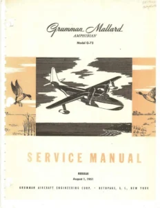
Beechjet 400A / Hawker 400XP (Model 400A) FAA Approved Airplane Flight Manual - PDF β€” PDF page 1 preview
Beechjet 400A / Hawker 400XP (Model 400A) FAA Approved Airplane Flight Manual - PDF β€” PDF page 51 preview
Beechjet 400A / Hawker 400XP (Model 400A) FAA Approved Airplane Flight Manual - PDF β€” PDF page 98 preview

This Beechjet 400A / Hawker 400XP (Model 400A) FAA Approved Airplane Flight Manual PDF is delivered instantly after payment. There is no shipping, no waiting, and no physical book to keep current by hand. Open the file on a laptop, tablet, or phone, print only the pages you need for a given flight, or load it on a shop computer for reference. The complete 1002-page Beechjet 400A / Hawker 400XP FAA Approved Airplane Flight Manual is ready to use the moment your download completes.
Reviews

There are no reviews yet.

Be the first to review “Beechjet 400A / Hawker 400XP (Model 400A) FAA Approved Airplane Flight Manual – PDF”

What Our Customers Say

β˜…β˜…β˜…β˜…β˜… Live reviews from customers
Loading customer reviews...
0
    0
    Your Cart
    Your cart is emptyReturn to Shop
    πŸ›’
    Recently Purchased
    πŸ•’ verified order