
Bell B35C MKII B40CR B40CM 6×6 ADT 6 Speed Parts Manual 872074 PDF
Original price was: $44.95.$26.95Current price is: $26.95.
Illustrated parts manual 872074 for Bell B35C MKII, B40CR MKII and B40CM MKII 6×6 ADT 6 speed machines – exploded views and numbered parts lists for engine, drivetrain, hydraulics, pneumatics, electrics, frame and body.
Description
Bell B35C MKII, B40CR MKII and B40CM MKII 6×6 ADT 6 Speed Parts Manual – Document 872074
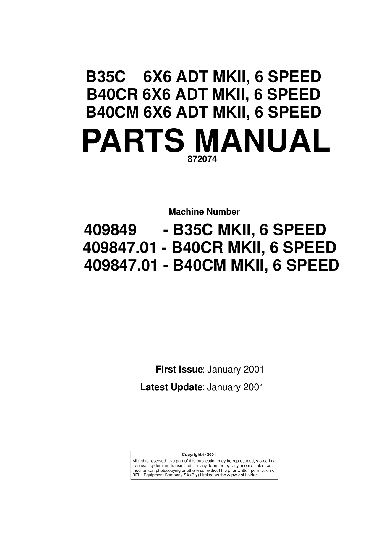
This Bell B35C MKII B40CR B40CM 6×6 ADT 6 Speed Parts Manual 872074 PDF is the illustrated parts catalogue for the Bell Equipment MKII six speed six wheel drive articulated dump trucks. It was produced for machine numbers 409849 (B35C MKII, 6 speed) and 409847.01 (B40CR MKII and B40CM MKII, 6 speed), with a first issue and latest update both dated January 2001. Every assembly in the book is presented as a pictorial breakdown with a matching numbered parts list, so a component seen on the drawing can be traced straight to its part number, description, quantity and, where relevant, the machine variant it belongs to.
Because the three truck models share a common drivetrain, chassis and cab architecture while differing in engine rating, axle ratio and cooling pack, the listings use remark columns to separate what fits a B35C MKII from what fits a B40CR MKII or B40CM MKII. That detail is what makes this manual useful in a parts department or workshop: it stops a B35C part number being ordered for a B40C machine, and it shows which components carry over across the range.
File Details
- Manual type: Illustrated parts manual (parts catalogue)
- Brand / manufacturer: Bell Equipment
- Models covered: B35C MKII, B40CR MKII, B40CM MKII – 6×6 ADT, 6 speed
- Document number: 872074
- First issue: January 2001
- Latest update: January 2001
- Machine numbers: 409849, 409847.01
- Language: English
- Page count: 436
- File format: PDF
Chapters Covered
- Section 1 – General Information
- VIN identification and VIN structure breakdown
- Technical documentation bulletin record
- List of abbreviations
- Serial number plates and their locations
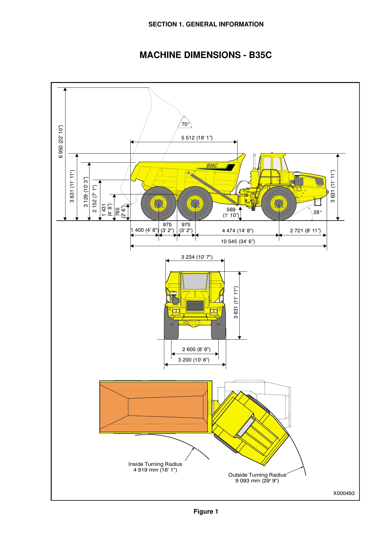
- Ordering information and machine dimensions
- Section 2 – Engine
- Engine and miscellaneous parts
- Engine to transmission coupling parts
- Air cleaner layout, pre cleaner and air cleaner assembly
- Exhaust assembly
- Fuel system, engine kill assembly and throttle assembly
- Intercooler circuit layout
- Engine cooling system and water level sender unit
- Section 3 – Drivetrain
- Transmission and miscellaneous parts
- Transmission cooling layouts
- Transfer case, input shaft assembly and idler shaft assembly
- Propshaft layouts and propshaft assemblies
- Oscillation through drive assembly
- Front suspension and axle, suspension struts RHS and LHS, rear suspension
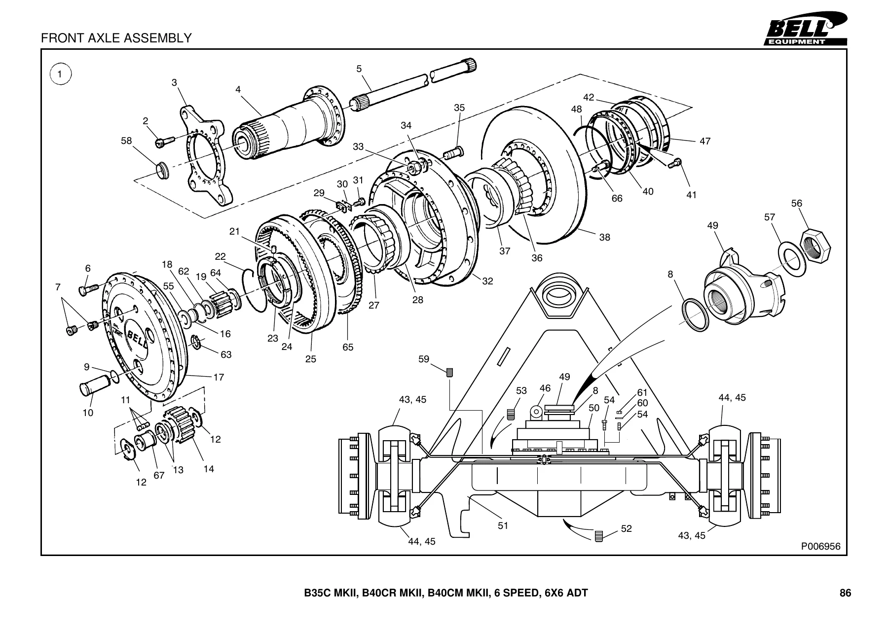
- Front axle assembly and front differential assembly
- Thru-drive axle assembly and thru-drive differential assembly
- Rear axle assembly and rear differential assembly
- Brake system and axle / brake pipe guards
- Brake caliper assembly, park brake and park brake assembly
- Wheel set
- Section 4 – Hydraulics
- Hydraulic system with emergency steering
- Cab tilt assembly
- Flow amplifier
- Hydraulic pump and rotation pump
- Control valve
- Steering cylinder, cab tilt cylinder and lift cylinder
- Hydraulic filter assembly
- Section 5 – Pneumatics
- Front chassis pneumatic system
- Cab pneumatic system
- Rear chassis pneumatic system
- C.T.D. layout
- Accelerator foot valve and air throttle control
- Charging valve and brake valve
- Air / hydraulic brake actuator and brake valve adaptor
- Pressure protection valve
- Unloader valve with integral air drier assembly
- Section 6 – Electrics
- Earth straps and harness earth points
- Electrical harnesses and components, front, rear and cab
- Starting and charging circuit
- Turn indicators and hazard circuit, lighting circuit, warning lights circuit, gauges circuit
- Overrev module circuit
- Airconditioner and wipe / wash circuit
- Reverse, stoplight and EVB circuit, bin and gear hold circuit
- Allison transmission HD 4560 VER 8 circuit
- Cold start circuit
- Battery balancer and radio cassette player
- Connectors 1 to 30 and plug illustrations B to E
- Instrument panels centre, LH and RH, circuit breaker box, batteries and related parts
- Windscreen wiper, rear lights, indicator and siren, headlights and front indicators, rotating beacon and interior light
- Section 7 – Frame and Body
- Cab exterior fittings, cab interior fittings and door handle assembly
- Steering column and windscreen washer reservoir
- Cab seats, seat assembly and cab mountings
- Airconditioner and heater system, evaporator / heater and condenser assembly
- Bin tilt lever assembly, bonnet assembly and bonnet latch assembly
- Front chassis and related parts, mudguard, rails and steps
- Hydraulic tank and battery box
- Exhaust stand and related parts, non slip pads
- Chassis curtains and mudguard extensions
- Articulation joint bearing assembly, articulation and oscillation assembly
- Steering cylinder mountings and oscillation lubrication pipes
- Rear frame and bin, tip cylinder mountings and bin heater assembly
- Decals and plates
Read as a whole, document 872074 gives a parts interpreter or workshop technician a complete component-level map of the B35C MKII, B40CR MKII and B40CM MKII. The engine group alone carries the oil filter assembly, starter motor, turbo gasket, fan, alternator, air conditioning compressor and belt, dipstick, injector pipe guards and the viscous hub, alongside the mounting hardware that holds the power unit in the chassis. Drivetrain coverage goes right down to individual bearings, thrust washers, circlips, planet gears, sun gears and ring gears inside the front, thru-drive and rear differential assemblies, and the brake section lists calipers, pipe guards, park brake actuator internals and the wheel set. Hydraulics and pneumatics are shown as complete circuit layouts with every hose, elbow, bulkhead fitting, T-piece, reducer and valve identified, while the electrics section breaks the machine into individual circuits – starting and charging, lighting, warning lights, gauges, cold start, transmission interface and connectors – each with its own component list. The result is a single reference that answers not only what a part is called, but where it sits in the assembly and how many are required.
Ordering Parts With Confidence
Using this manual means the part number on the order line matches the machine in the yard. The remark column flags components that apply only to B35C MKII machines or only to B40CR MKII and B40CM MKII machines, so a cylinder head cover, an axle assembly, a differential head ratio, a hydraulic tank or a cooling fan is not picked from the wrong column. Grouped quantities are printed against each item, which removes the guesswork when a single assembly consumes eight washers, twelve screws or twenty-four wheel nuts. And because the illustrations are exploded rather than photographic, components that are hidden inside an axle, a transfer case or a control valve are still visible and still numbered.
What This Parts Manual Lets You Do
With the Bell B35C MKII B40CR B40CM 6×6 ADT 6 Speed Parts Manual 872074 open on the bench, a technician can strip and rebuild the transfer case, rebuild a front or thru-drive differential with the correct bearings and wear washers, replace a suspension strut seal kit, re-pipe a hydraulic or pneumatic circuit after a hose failure, trace an electrical fault through the starting, lighting or transmission interface circuits, and order the right decal, guard or mounting plate for a body repair. Correct part numbers and correct quantities matter on machines of this size – a wrongly ordered axle component or differential ratio can idle a truck for days, and a mis-identified brake or steering part is a safety issue, not just a delay. Having the manufacturer’s own exploded views and part listings on hand turns a speculative phone call into a definite order.
IMAGES PREVIEW
Instant PDF Delivery
The manual is supplied as a downloadable PDF. There is no shipping, no waiting on a courier and no physical book to lose in the workshop. Once payment is complete the file is available immediately, and it can be opened on a laptop in the office, a tablet on the workshop floor or a phone next to the machine, with individual pages printed when a clean copy is wanted at the bench.



Reviews
There are no reviews yet.