★ TRUSTED BY 321,897+ PROFESSIONALS WORLDWIDE
🏒
Trusted Business
Verified & Licensed
πŸ›‘οΈ
Virus Free Files
100% Safe Downloads
πŸ”’
Secure Payment
SSL Protected
⚑
Instant Delivery
Available Immediately
Sale!

Benelli TRK 251 BJ250-18 Service Manual – Complete Workshop Repair Guide

Original price was: $34.95.Current price is: $20.95.

Comprehensive Benelli TRK 251 (BJ250-18) service manual covering engine, EFI, cooling, brakes, suspension, electrical, and full wiring diagrams for China, European, and non-European models.

⚑
Instant PDF Download
Available immediately
πŸ’Ύ
Save to Your Device
Download & keep forever
πŸ›‘οΈ
Antivirus Scanned
100% virus-free
🌍
Trusted Worldwide
175,000+ customers

Description

Benelli TRK 251 BJ250-18 Service Manual

This is the complete workshop service manual for the Benelli TRK 251, covering the BJ250-18 model in its China, European regulation, and non-European regulation variants. Whether you are performing routine maintenance, diagnosing an EFI fault, rebuilding the top end, or tracing an electrical gremlin through the wiring harness, this manual provides the procedures, specifications, and exploded views needed to get the job done correctly. It is the same type of document a professional technician would use in a well-equipped workshop.

File Details

  • Manual type: Motorcycle Maintenance / Service Manual
  • Brand: Benelli
  • Model: TRK 251 (BJ250-18)
  • Language: English
  • Page count: Approximately 490 pages
  • File format: PDF
  • Coverage: China, European regulation, and non-European regulation models

Chapters Covered

  • Introduction and Important Notices
  • Chapter I β€” Basic Information
    • Maintenance instructions
    • Battery installation
    • Sharp edge and solvent safety
    • Cleaning, sorting, and storing removed parts
    • Fastening sequence and locking torque
    • Gaskets, O-rings, liquid gasket, and locking agent
    • Press fitting, bearings, oil seals, circlips
    • Lubrication, engine rotation direction, wiring
    • Cable arrangement and tools
    • Model information and basic specifications
    • General technical parameters and unit conversion table
  • Chapter II β€” Regular Maintenance
    • Regular maintenance table
    • Torque and locking agent specifications
    • EFI β€” throttle control, idle speed, fuel hose, vapor recovery
    • Cooling system β€” coolant level, radiator pipes
    • Engine cylinder head and valve clearance
    • Clutch β€” control system and free stroke
    • Wheel/tire β€” pressure, wear, bearings
    • Final drive β€” chain lubrication, slack, alignment, wear
    • Brake β€” hoses, free stroke, fluid level, pad wear, brake light
    • Suspension β€” front fork, rear shock absorber
    • Steering β€” clearance, adjustment, bearing lubrication
    • Electrical β€” lights, switches, headlight accuracy, sidestand switch
    • Frame lubrication and fastener tightness
    • Replacement procedures β€” air filter, fuel hose, coolant, radiator hose, oil, brake hose, brake fluid, master cylinder rubber, caliper rubber, spark plug
  • Chapter III β€” Electronic Fuel Injection (EFI)
    • EFI system introduction and component positions
    • Technical parameters
    • Fuel tank β€” exploded view, disassembly, inspection, installation
    • Fuel vapor recovery system
    • Precautions for EFI overhaul
    • ECU β€” engine controller MT05, appearance, disassembly, installation
    • Fuel pump β€” working principle, disassembly, inspection, installation
    • Throttle body β€” working principle, sensors, cleaning, installation
    • Fuel injector β€” operation, seals, installation, replacement
    • Engine water temperature sensor
    • Intake temperature sensor
    • Inlet pressure sensor
    • Oxygen sensor
    • Idle speed stepper motor
    • Canister solenoid valve (ECP)
    • Fault maintenance and diagnosis β€” fault lamp, diagnostic apparatus, PCHUD software, fault code table
    • Common troubleshooting methods
    • Daily use and maintenance
  • Chapter IV β€” Cooling System
    • Exploded view of cooling system and water pump
    • Coolant flow diagram
    • Technical parameters
    • Coolant β€” deterioration check, level check, draining, adding, pressure test, flushing
    • Coolant reserve tank disassembly/installation
    • Water pump β€” disassembly, installation, impeller inspection
    • Radiator β€” disassembly/installation, fan, inspection, cap inspection, filler inspection
    • Thermostat β€” disassembly, installation, inspection
    • Hose and pipeline β€” installation, inspection
    • Water temperature sensor β€” disassembly, installation, inspection

    Complete PDF Bookmark Tree

    Complete Bookmarks

    The complete bookmarks in the β€œBenelli TRK 251 BJ250-18 Service Manual – Complete Workshop Repair Guide” are as follows:

    Exhaust Emission Control Informationp. 3
    It is strictly forbidden to modify the noise contrp. 5
    Prefacep. 23
    Chapter I Basic Informationp. 23
    Maintenance instructionsp. 24
    Installation of Batteryp. 25
    Sharp edge of partp. 25
    Vehiclep. 25
    Cleaning the motorcycle before disassemblyp. 26
    Sort out and clean the removed partsp. 26
    Store the removed partsp. 26
    Checkp. 26
    Replacement partp. 27
    Assembly sequencep. 27
    Fastening sequencep. 27
    Locking torquep. 27
    Forcep. 28
    Gasket, O-ringp. 28
    Liquid gasket, locking agentp. 28
    Press fittingp. 28
    Ball bearing and needle bearingp. 29
    Oil seal, grease sealp. 29
    Circlip, cotter pinp. 29
    Lubricationp. 30
    Engine rotation directionp. 30
    Wirep. 30
    Cable connector checkp. 30
    1. Disconnectp. 31
    2. Checkp. 31
    3. Checkp. 31
    4. Checkp. 31
    5. Checkp. 32
    Cable arrangementp. 32
    Toolsp. 33
    Model informationp. 33
    Chinap. 34
    Europep. 34
    Non-Europeanp. 35
    Important recognitionp. 36
    Basic specificationsp. 37
    General Technical Parametersp. 38
    Unit conversion tablep. 42
    Chapter II Regular Maintenancep. 44
    Regular maintenance tablep. 45
    Torque and locking agentp. 47
    Main locking torque specificationsp. 48
    Locking torque and related parameters of nuts, bp. 51
    Technical parametersp. 53
    Regular maintenance proceduresp. 55
    Fuel Injection System (EFI)p. 56
    Check throttle control systemp. 56
    Check fuel hose (fuel leak, hose rupture, hose insp. 57
    Check fuel vapor recovery system (models in China,p. 58
    Cooling Systemp. 60
    Inspection of cooling fluid levelp. 60
    Check radiator pipes (coolant leakage, radiator pip. 60
    Engine cylinder head and cylinder head coverp. 61
    Checking valve clearance;p. 61
    Adjusting the valve clearancep. 62
    Check whether the air inlet unit has been damagedp. 66
    Clutchp. 67
    Check if the clutch control system is normalp. 67
    Check the free stroke of clutch handlep. 67
    Wheel/tirep. 67
    Check the tire pressurep. 68
    Check wheel / tire for wearp. 68
    Check the wear of treadp. 68
    Check whether the wheel bearing has been damagedp. 69
    Final Drive Mechanismp. 69
    Check the lubrication state of drive chainp. 70
    Check whether the drive chain is slackp. 70
    Adjust drive chain slacknessp. 70
    Check wheel alignmentp. 72
    Check the wear of drive chainp. 72
    Check the wear of chain guidep. 73
    Brakep. 73
    Check brake hoses and brake lines for damage and ep. 74
    Free stroke of front brakep. 74
    Free stroke of rear brakep. 74
    Inspection of brakep. 75
    Inspection of brake fluid levelp. 75
    Inspection of wear of brake padp. 76
    Inspection of brake light switchp. 77
    Check the output voltage of speed sensorp. 77
    Suspension system:p. 79
    Check front fork / rear shock absorberp. 79
    Check the front fork shock absorber for oil leakagp. 79
    Check the rear shock absorber for oil leakagep. 80
    Steering systemp. 80
    Check steering clearancep. 81
    Adjust the steering seat properlyp. 81
    Lubricate steering stem bearingsp. 82
    Electrical Systemp. 82
    Check lights and switchesp. 83
    Step Ip. 83
    Step IIp. 84
    Step IIIp. 84
    Check the headlight accuracyp. 86
    Adjustment of headlight beamp. 87
    Check the sidestand flameout switchp. 87
    Check emergency stop switchp. 89
    Step Ip. 89
    Step IIp. 89
    Othersp. 89
    Lubricate frame partsp. 90
    Pivot shaft: lubricate it with greasep. 90
    Wire: lubricate it with greasep. 90
    Cable: lubricate it with greasep. 90
    Check the tightness of bolts, nuts and fastenersp. 91
    Bolts, nuts and fasteners to be checkedp. 91
    Replacement partp. 92
    Replace of air filter elementp. 93
    Replacement of fuel hosep. 95
    Replacement of coolantp. 96
    Replacement of radiator hosep. 99
    Replace oilp. 100
    Replacement of brake hosep. 101
    Replacement of rear brake hosep. 103
    Replacement of brake fluidp. 104
    Replacement of rubber parts of master cylinderp. 107
    Disassemble front master cylinderp. 108
    Disassembly of rear master cylinderp. 108
    Assembly of master cylinderp. 109
    Replacement of rubber parts of caliperp. 109
    Disassembly of front caliperp. 110
    Assembly of front caliperp. 110
    Disassembly of rear caliperp. 111
    Assembly of rear caliperp. 112
    Replace spark plugp. 114
    Chapter III Fuel Injection System (EFI)p. 115
    Introduction to EFIp. 117
    EFI systemp. 118
    EFI part positionp. 120
    Technical parametersp. 127
    Fuel tankp. 130
    Exploded view of fuel tankp. 130
    Fuel vapor recovery systemp. 131
    Fuel tankp. 133
    Disassemble fuel tankp. 133
    Check the fuel tankp. 134
    Install the fuel tankp. 134
    Precautions for EFI overhaulp. 134
    Precautions for EFI overhaulp. 135
    ECUp. 136
    Engine controller (MT05 ECU)p. 137
    ECU appearancep. 137
    ECU disassemblyp. 137
    ECU installationp. 137
    Precautions for ECUp. 137
    ECU Power Supply Requirementsp. 138
    ECU temperature requirementsp. 138
    fuel pumpp. 138
    Working principle of fuel pumpp. 139
    Appearance of fuel pump:p. 139
    Fuel pump compositionp. 140
    Fuel pump label and logop. 140
    Working environment of fuel pumpp. 140
    Maintenance process of fuel pump:p. 141
    Safety Protection:p. 141
    Fault diagnosis of fuel pump assembly:p. 142
    Disassembly of fuel pump assembly:p. 142
    Installation of fuel pump assembly:p. 142
    Fuel pressure release process:p. 143
    Fuel leakage check process:p. 143
    Notes for Use:p. 143
    Throttle Bodyp. 144
    Working Principle of Throttle Body:p. 145
    Appearance of Throttle Body:p. 145
    Technical parametersp. 145
    Throttle Body:p. 146
    Throttle position sensor:p. 146
    Idle air control valve:p. 146
    Operating temperature of throttlep. 146
    Disassemble throttle bodyp. 146
    Cleaning Method of Throttlep. 146
    install throttle bodyp. 146
    Notes for the Installation of Throttle Bodyp. 147
    Notes for the Use of Throttle Bodyp. 147
    Fuel injectorp. 148
    Working Principle of Fuel Injector:p. 148
    Appearance of fuel injectorp. 148
    Fuel injector sealp. 148
    O-ring Seal Connected to Oil Rail or Oil Injectionp. 149
    O-ring Seal Connected to Intake Pipe Endp. 149
    List of recommended lubricantsp. 149
    Overvoltage Impact of fuel injectorp. 149
    Temperature range of fuel injector:p. 149
    Fuel contaminants of fuel injectorp. 150
    Fuel injector harness arrangementp. 150
    Notes for Use of Fuel Injectorp. 150
    Installation requirements for fuel injectorp. 151
    Replacement Method of Fuel Injectorp. 151
    Replaceability of fuel injectorp. 152
    Blocking of Fuel Injectorp. 152
    Engine water temperature sensorp. 152
    Working principles of engine water temperature senp. 153
    Appearance of engine water temperature sensorp. 153
    Installation requirements for engine water temperap. 153
    Operating environment of engine water temperaturep. 153
    Electrical environment of engine water temperaturep. 153
    Cleaning of engine water temperature sensorp. 154
    Inlet temperature sensorp. 154
    Working principle of intake temperature sensorp. 155
    Appearance of intake temperature sensorp. 155
    Technical parametersp. 155
    Pin position definition and function diagramp. 156
    Installation position of intake temperature sensorp. 156
    Cleanp. 156
    Inlet pressure sensorp. 156
    Working principles of inlet pressure sensorp. 157
    Appearance of inlet pressure sensorp. 157
    Operating environmentp. 157
    Storage environmentp. 157
    Electrical environmentp. 158
    Pin definitionp. 158
    Locationp. 158
    Cleanp. 158
    Oxygen sensorp. 159
    Working principle of oxygen sensorp. 160
    Appearance of oxygen sensorp. 160
    Technical parametersp. 160
    Installation requirementsp. 160
    Oxygen sensor pin definition:p. 161
    Characteristic curvep. 161
    Requirements for fuel qualityp. 162
    Idle speed stepper motorp. 162
    Working principle of idle speed stepper motorp. 163
    Appearance of idle speed stepper motorp. 163
    Pin Definitionp. 164
    Characteristic parameters:p. 164
    Cleanp. 164
    Canister solenoid valve (ECP)p. 164
    Overview of working principlep. 165
    Appearancep. 165
    Pin of ECP solenoid valvep. 165
    Technical parametersp. 165
    Installation requirementsp. 166
    Fault Maintenance and Diagnosis Method of EFI Sysp. 166
    Conduct diagnosis directly using the flashing faulp. 167
    Diagnose fault using diagnostic apparatusp. 169
    Check fault using diagnostic software PCHUDp. 170
    Common troubleshooting methods for electronic fuep. 176
    Maintenance toolp. 177
    Engine working data flow displayed by diagnostic ap. 177
    Step Ip. 177
    Step IIp. 177
    Step IIIp. 178
    Simple Troubleshootingp. 178
    Daily Use and Maintenancep. 178
    Fault phenomenon-Start Faultp. 178
    Fault phenomenonβ€”Start failure with temperingp. 180
    Fault phenomenonβ€”Instable idle speedp. 180
    Fault phenomenonβ€”Too high or too low idle speed (ip. 180
    Fault phenomenonβ€”Instable idle speed with decelerap. 180
    Fault phenomenonβ€”Insufficient power of deceleratiop. 180
    Fault phenomenonβ€”Slight burning phenomenonp. 180
    Fault phenomenonβ€”Fault lamp is on, but fault codep. 180
    Fault phenomenonβ€”Extremely high fuel consumptionp. 181
    Chapter IV Cooling Systemp. 183
    Exploded view of cooling systemp. 183
    Exploded view of water pumpp. 186
    Coolant flow diagramp. 187
    Technical parametersp. 189
    Cooling fluidp. 190
    Check coolant for deteriorationp. 190
    Check coolant levelp. 190
    Drain the coolantp. 190
    Add the coolantp. 190
    Detect pressurep. 190
    Flushing Cooling Systemp. 190
    Disassembly/Installation of Coolant Reserve Tankp. 191
    Water pumpp. 191
    Disassembly of Water Pumpp. 192
    Installation of Water Pumpp. 193
    Check water pump impellerp. 193
    Radiatorp. 193
    Disassembly of Radiator and Radiator Fanp. 194
    Assembly of Radiator and Radiator Fanp. 195
    Inspection of Radiatorp. 195
    Inspection of radiator coverp. 196
    Inspection of Radiator Fillerp. 198
    Thermostatp. 198
    Disassembly of Thermostatp. 199
    Installation of Thermostatp. 200
    Inspection of Thermostatp. 200
    Hose and Pipelinep. 201
    Installation of Hosep. 202
    Check hosep. 202
    Water temperature sensorp. 202
    Disassembly / installation of water temperature sep. 203
    Check water temperature sensorp. 203
    Chapter V Enginep. 204
    Lubrication Systemp. 206
    Exploded view of fuel pumpp. 206
    Oil flow diagramp. 208
    Preparatory informationp. 208
    Technical parametersp. 209
    Fuel pumpp. 210
    Disassembly of fuel pumpp. 210
    Inspection of Fuel Pumpp. 211
    Installation of fuel pumpp. 212
    Sub-assembly of Cylinder Headp. 213
    Exploded View of Cylinder Headp. 213
    Exploded view of camshaft and valvep. 215
    Exploded view of timing drive mechanismp. 216
    Preparatory informationp. 217
    Technical parametersp. 218
    Special tools and sealantsp. 218
    Cylinder headp. 221
    Disassembly of cylinder headp. 221
    Valve decompositionp. 223
    Inspection of combustion chamberp. 223
    Inspection of cylinder head joint surfacep. 223
    Inspection of intake and exhaust springsp. 224
    Inspection of valve stemp. 224
    Inspection of valve guidep. 225
    Replacement of Valve Guidep. 225
    Adjustment of Valve Seat Ringp. 226
    Installation of Cylinder Headp. 227
    Tensionerp. 228
    Function of tensionerp. 228
    Disassembly of Tensionerp. 229
    Assembly of Tensionerp. 229
    Inspection of Tensionerp. 229
    Cylinder Block and Pistonp. 230
    Exploded View of Cylinder Bodyp. 230
    Exploded view of piston / crankshaftp. 231
    Preparatory informationp. 232
    Technical parametersp. 233
    Inspection and replacement of cylinder blockp. 234
    14.3 Disassembly of Cylinder Blockp. 234
    Installation of Cylinderp. 234
    Check cylinder blockp. 235
    Pistonp. 235
    Disassembly of Pistonp. 235
    Installation of Pistonp. 236
    Check the piston, piston pin and piston ringp. 237
    Crankshaft connecting rodp. 240
    Exploded view of crankshaft connecting rodp. 240
    Preparatory informationp. 242
    Technical parametersp. 243
    13.6 Crankshaft Connecting Rod Combinationp. 244
    Disassembly of Crankshaft Connecting Rod Combinatip. 244
    Assemblyp. 244
    Checkp. 244
    Balance shaftp. 245
    Function of balancer shaftp. 245
    Disassembly of balancer shaftp. 245
    Assembly of balancer shaftp. 246
    Inspection of balancer shaftp. 246
    Clutchp. 247
    Exploded view of clutchp. 247
    Special toolsp. 249
    Disassembly of clutchp. 250
    Disassembly of Clutchp. 252
    Installation of clutchp. 253
    Inspection of clutchp. 253
    Gearshift Mechanismp. 254
    Exploded View of Gearshift Mechanismp. 254
    Disassembly of Gearshift Mechanismp. 257
    Installation of Gearshift Mechanismp. 258
    Inspection of Gearshift Mechanismp. 258
    Disassembly of primary / auxiliary shaft componentp. 260
    Disassembly of primary / auxiliary shaft componentp. 261
    Inspection of primary / auxiliary shaft componentp. 262
    Chapter VI Finished Motorcyclep. 262
    Wheel/tirep. 267
    Exploded view of front wheel/tirep. 268
    Exploded view of rear wheel/tirep. 268
    Technical parametersp. 271
    Special toolsp. 272
    Wheel (rim)p. 272
    Disassemble front wheelp. 273
    Install front wheelp. 274
    Disassemble rear wheelp. 275
    Installation of rear wheelp. 276
    Check wheelp. 277
    Check the axlep. 278
    Adjustment of static balance of rimp. 278
    Adjustment / inspection of tire pressurep. 280
    Check tirep. 280
    Disassemble tirep. 280
    Mount tirep. 281
    Hub bearingp. 283
    Disassemble hub bearingp. 284
    Install hub bearingp. 284
    Inspection of hub bearingp. 285
    Hub bearing lubricationp. 285
    Transmission mechanismp. 286
    Exploded view of drive mechanismp. 286
    Technical parametersp. 288
    Special toolsp. 289
    Drive chainp. 289
    Check the slackness of drive chainp. 290
    Inspection of slackness of drive chainp. 290
    Inspection / adjustment of wheel alignmentp. 290
    Inspection of wear of drive chainp. 290
    Drive chain lubricationp. 290
    Disassembly of drive chainp. 290
    Installation of drive chainp. 291
    Sprocket, collar, collar bearingp. 292
    Disassembly of rear sprocketp. 293
    Installation of rear sprocketp. 293
    Disassemble collar bearingp. 294
    Install collar bearingp. 294
    Check collar bearingp. 294
    Lubricate collar bearingp. 295
    Check the damper of collarp. 295
    Check the wear of sprocketp. 295
    Check the deformation of rear sprocketp. 295
    Brakep. 297
    Exploded View of Brakep. 297
    Technical parametersp. 299
    Special toolsp. 300
    Brake lever, brake pedalp. 300
    Adjustment of position of brake leverp. 301
    Inspection of position of brake pedalp. 301
    Adjustment of position of brake pedalp. 301
    Disassembly of brake pedalp. 302
    Installation of brake pedalp. 302
    Caliperp. 304
    Disassembly of front caliperp. 304
    Disassembly of rear caliperp. 304
    Installation of caliperp. 304
    Disassembly of front caliperp. 305
    Assembly of front caliperp. 305
    Diassembly of rear caliperp. 305
    Assembly of rear caliperp. 305
    Inspection of fluid sea of caliper for leakagep. 305
    Inspection of dust seal of caliper for damagep. 305
    Inspection of the caliper piston and brake cylindep. 306
    Brake padp. 306
    Remove the front brake padp. 306
    Installation of front brake padp. 307
    Disassembly of Rear Brake Padp. 307
    Installation of Rear Brake Padp. 308
    Inspection of wear of brake padp. 308
    Master cylinderp. 308
    Disassemble front master cylinderp. 308
    Installation of front master cylinderp. 309
    Disassembly of rear master cylinderp. 310
    Installation of rear master cylinderp. 311
    Disassembly of front master cylinderp. 311
    Disassembly of rear master cylinderp. 311
    Assembly of master cylinderp. 311
    Check the master cylinder (visual inspection)p. 311
    Brake discp. 312
    Disassembly of front brake discp. 312
    Disassembly of rear brake discp. 312
    Installation of brake discp. 313
    Inspection of wear of brake discp. 313
    Inspection of deformation of brake discp. 314
    Brake fluidp. 314
    Inspection of level of brake fluidp. 314
    Replacement of brake fluidp. 314
    Exhaust the air inside the brake linep. 314
    Brake hosep. 315
    Disassembly / installation of brake hose and brakep. 315
    Inspection of Brake Hoses and Brake Linesp. 315
    Anti-lock brake system (ABS)p. 316
    Part positionp. 316
    ABS system circuit diagramp. 316
    Pin namep. 317
    ABS overhaulp. 318
    Precautions for ABS overhaulp. 319
    Overview of ABS fault removalp. 320
    ABS diagnostic flow chartp. 322
    Carry out the pre-diagnosis inspection (Phase 1)p. 324
    Carry out the pre-diagnosis inspection (Phase 2)p. 325
    Overview of diagnosisp. 326
    Check the ABS indicator (LED).p. 326
    ABS indicator (LED) is on (rotate the ignition swip. 327
    ABS indicator (LED) is on (motorcycle is driving –p. 328
    The difference between front and rear wheel speedsp. 328
    Wheel speed sensor is open or shorted (front: C008p. 329
    Check the line of wheel speed sensor (fault code:p. 329
    Relay fault (C0044-C0046)p. 329
    ABS normally open valve solenoid circuit is open-cp. 329
    ABS normally closed valve solenoid circuit is openp. 329
    ABS voltage is too high, ABS voltage is too low (tp. 329
    ABS pump or motor fault (C0070-C0074)p. 329
    Intermittent signal of wheel speed sensor (front:p. 330
    ABS wheel speed difference is too highp. 330
    Brake diode breakdown (C0062)p. 330
    Brake switch line fault (C0060-C0061)p. 330
    ABS indicator light (LED) fault (C0210-C0213)p. 330
    Speed output port fault (C0230-C0231)p. 330
    Front wheel speed sensor signal is abnormal (faultp. 331
    Rear wheel speed sensor signal is abnormal (faultp. 331
    Check ECU (fault code: C0044-C0046)p. 332
    ABS hydraulic systemp. 332
    Disassemble ABS hydraulic mechanismp. 332
    Install ABS hydraulic mechanismp. 334
    Check ABS hydraulic mechanismp. 335
    Speed sensorp. 336
    Remove front wheel speed sensorp. 336
    Install front wheel speed sensorp. 336
    Remove rear wheel speed sensorp. 336
    Install rear wheel speed sensorp. 337
    Check front wheel speed sensorp. 337
    Check the clearance of wheel speed sensorp. 338
    Check the gear ring of wheel speed sensorp. 338
    Suspension systemp. 339
    Exploded view of front suspension systemp. 340
    Exploded view of rear suspension systemp. 341
    Technical parametersp. 344
    Special toolsp. 345
    Front Shock Absorberp. 345
    Disassembly of Front Shock Absorberp. 346
    Installation of Front Shock Absorberp. 346
    Replacement of Front Shock Absorber Fluidp. 347
    Disassembly of Front Shock Absorberp. 350
    Inspection of inner tube and outer tubep. 352
    Inspection of Dust Sealp. 352
    Inspection of Spring Tensionp. 353
    Rear shock absorberp. 354
    Adjustment of pretightening force of springp. 354
    Disassembly of Rear Shock Absorberp. 355
    Assembly of Rear Shock Absorberp. 356
    Inspection of Rear Shock Absorberp. 356
    Rear rocker armp. 356
    Disassembly of Swing Armp. 357
    Installation of Swing Armp. 358
    Disassembly of Swing Arm Bearingp. 358
    Installation of Swing Arm Bearingp. 359
    Check swing arm bearingp. 359
    Check the chain guidep. 359
    Control Systemp. 359
    Exploded View of Control Systemp. 360
    Special toolsp. 362
    Control Systemp. 362
    Inspection of Control Systemp. 363
    Adjustment of Control Systemp. 363
    Handlebarp. 363
    Disassembly of Handlebarp. 364
    Installation of handlebarp. 365
    Steering stemp. 366
    Disassembly of Steering Stem and Steering Stem Beap. 367
    Installation of Steering Stem and Steering Stem Bep. 368
    Lubrication of Steering Stem Bearingp. 370
    Inspection of Deformation of Steering Stemp. 370
    Framep. 371
    Exploded View of Framep. 371
    Exploded view of left footpegp. 372
    Exploded view of right footpegp. 374
    Exploded View of Mufflerp. 376
    Exploded View of Rack and Luggage Carrierp. 378
    Exploded View of Fenderp. 381
    Exploded View of Headlight Coverp. 382
    Exploded View of Cowlingp. 385
    Exploded View of Fuel Tank Coverp. 387
    Exploded View of Seat Cushions and Coversp. 389
    Exploded View of Engine Accessoriesp. 390
    Seat Cushionp. 392
    Disassembly of seat cushionp. 392
    Installation of seat cushionp. 392
    Coverp. 392
    Disassembly of Left Coverp. 393
    Installation of Left Coverp. 393
    Disassembly of Right Coverp. 393
    Installation of Right Coverp. 393
    Disassembly of left coverp. 394
    Installation of left coverp. 394
    Disassembly of right coverp. 394
    Installation of right coverp. 394
    Rear rack and side case bracketp. 394
    Disassembly of side case bracketp. 395
    Installation of side case bracketp. 395
    Disassembly of rear rackp. 396
    Installation of rear rackp. 397
    Side coverp. 398
    Disassembly of side coverp. 398
    Installation of Side Coverp. 398
    Rear fenderp. 398
    Disassembly of rear fenderp. 399
    Installation of rear fenderp. 399
    Front fenderp. 400
    Disassembly of Front Fenderp. 400
    Installation of Front Fenderp. 400
    Windshield and cowlingp. 401
    Disassembly of windshieldp. 401
    Disassembly of cowlingp. 402
    Installation of windshield and cowlingp. 402
    Headlight cover and left and right front panelp. 403
    Disassembly of headlight coverp. 403
    Installation of headlight cover and left and rightp. 406
    Tank coverp. 406
    Disassembly of Fuel Tank Coverp. 407
    Installation of Fuel Tank Coverp. 407
    Framep. 407
    Disassembly of Framep. 408
    Installation of Framep. 408
    Inspection of Framep. 409
    Sidestandp. 409
    Disassembly of Sidestandp. 410
    Installation of Sidestandp. 410
    Left Front Footpegp. 410
    Disassembly of Left Front Footpegp. 411
    Installation of Left Front Footpegp. 411
    Left Rear Footpegp. 412
    Disassembly of Left Rear Footpegp. 413
    Installation of Left Rear Footpegp. 413
    Front Right Footpegp. 413
    Disassembly of Front Right Footpegp. 414
    Installation of Front Right Footpegp. 414
    Rear Right Footpegp. 414
    Disassembly of Rear Right Footpegp. 415
    Installation of Rear Right Footpegp. 415
    Mufflerp. 416
    Disassembly of mufflerp. 416
    Installation of Mufflerp. 417
    Disassembly/Installation of Enginep. 417
    Exploded View of Disassembly/Installation of Enginp. 418
    Disassembly of Enginep. 419
    Installation of Enginep. 424
    Chapter VII Electrical Systemp. 427
    Precautionsp. 430
    Technical parametersp. 430
    Special toolp. 431
    Electrical wiringp. 432
    Wiring checkp. 433
    Charging Systemp. 433
    Charging system circuit diagramp. 434
    Batteryp. 434
    Disassemble batteryp. 435
    Install batteryp. 435
    Activation of batteryp. 436
    First chargep. 437
    Inspection of charging statep. 439
    Alternatorp. 441
    Remove alternatorp. 441
    Check the alternatorp. 442
    Install the alternatorp. 442
    Voltage regulator/rectifierp. 442
    Remove rectifierp. 443
    Inspection of Circuit at Main Wiring Terminalp. 443
    Check rectifierp. 443
    Install rectifierp. 443
    Ignition Systemp. 444
    Ignition system circuit diagramp. 444
    Precautions for operationp. 444
    Crankshaft sensorp. 445
    Remove crankshaft position sensorp. 446
    Check crankshaft position sensorp. 446
    Ignition coilp. 446
    Remove ignition coil:p. 447
    Check ignition coilp. 447
    Installation of ignition coilp. 447
    Spark plugp. 448
    Inspection of spark plugp. 448
    Checkp. 448
    Check IC igniterp. 449
    ECU unitp. 449
    Ignition System Troubleshootingp. 449
    Starter Systemp. 451
    Starter system circuit diagramp. 451
    Starting Motorp. 451
    Remove the starter motorp. 452
    Check the starter motorp. 452
    Check the brushp. 452
    Clean and check commutatorp. 453
    Check the brush leadp. 453
    Check the right end cover assemblyp. 454
    Install the starter motorp. 454
    Starter relayp. 454
    Remove starter relayp. 455
    Inspection of action of starter relayp. 455
    Install starter relayp. 455
    Lighting Systemp. 455
    Headlightp. 456
    Disassemble headlight relay controllerp. 456
    Check headlight relay controllerp. 456
    Install headlight relay controllerp. 456
    Remove headlightp. 457
    Replace headlight bulbp. 457
    Replacement of headlight bulbp. 457
    Install headlightp. 457
    Turn signal lightp. 457
    Remove front turn signal lightp. 457
    ●Remove rear turn signal lightp. 458
    Replacement of Turn Signal Light Bulbp. 458
    Install turn signal lightp. 458
    Remove flasherp. 458
    Check flasherp. 459
    Install flasherp. 459
    Taillightp. 459
    Remove taillightp. 459
    Replacement of taillight bulbp. 460
    Install taillightp. 460
    License plate lightp. 460
    Remove license plate lightp. 460
    Replacement of license plate light bulbp. 460
    Install license plate lightp. 460
    Gaugep. 461
    Remove meterp. 461
    Install meterp. 461
    Switch and Sensor and Other Partsp. 462
    Power lock switchp. 463
    Remove power lockp. 463
    Check power lockp. 463
    Install the power lockp. 463
    Handlebar Switchp. 463
    Switch state (non-headlights are always on)p. 464
    Switch state (headlights are always on)p. 465
    Inspection of time for turning on brake lightp. 465
    Adjust the time for turning on the brake lightp. 466
    Check switchp. 466
    Connect the rear brake light switchp. 466
    Connect the sidestand switchp. 466
    Speed sensorp. 466
    Remove speed sensorp. 467
    Check the speed sensorp. 467
    Install speed sensorp. 468
    Oxygen sensorp. 469
    Remove oxygen sensorp. 469
    Check oxygen sensorp. 469
    Install oxygen sensorp. 469
    Fuel level sensorp. 469
    Remove fuel level sensorp. 470
    Check fuel level sensorp. 470
    Installation of fuel level sensorp. 470
    Hornp. 471
    Disassemble hornp. 471
    Check the hornp. 471
    Install hornp. 471
    Fanp. 471
    Remove the fanp. 472
    Check the fanp. 472
    Install the fanp. 473
    Water temperature switchp. 473
    Remove the water temperature switchp. 474
    Check the water temperature switchp. 474
    Install the water temperature switchp. 474
    Relay and fuse boxp. 474
    Remove relay and fuse boxp. 475
    Inspection of relay circuit:p. 476
    Check relay circuit (disconnect battery)p. 476
    Check relay circuit (with battery)p. 476
    Internal circuit of relay boxp. 477
    Fusep. 478
    Remove the fusep. 479
    Installation of fusep. 480
    Check the fusep. 481
    Chapter VIII Appendixesp. 482
    ●Winding method of cables, wires and hosesp. 483
    Alignment of main cable:p. 484
    Alignment of clutch:p. 491
    Alignment of brake pipe:p. 493
    Other matters:p. 497
    Troubleshooting Guidep. 499
    Diagnostic procedure for the fault that engine canp. 500
    Starter motor does not work:p. 500
    The starter motor is rotating, but the engine doesp. 500
    The engine does not run:p. 500
    Fuel does not flow:p. 500
    No sparks; sparks are weak:p. 500
    There is a problem with the fuel/air mixture:p. 501
    Too low cylinder pressure:p. 501
    It cannot run properly at a low speed:p. 501
    Sparks are weak:p. 501
    There is a problem with the fuel/air mixture:p. 501
    The cylinder pressure is low:p. 501
    Others:p. 502
    It cannot run properly at a high speed or the powep. 502
    Ignition is abnormal:p. 502
    There is a problem with the fuel/air mixture:p. 502
    The cylinder pressure is low:p. 502
    There is a click sound:p. 502
    Others:p. 502
    The temperature is too high:p. 503
    Ignition is abnormal:p. 503
    The muffler is overheated:p. 503
    There is a problem with the fuel/air mixture:p. 503
    The cylinder pressure is high:p. 503
    The output force of engine is insufficient:p. 503
    Not properly lubricated:p. 503
    The fuel cooler is abnormal:p. 503
    Meter is abnormal:p. 503
    The coolant is abnormal:p. 503
    The components of cooling system are not working pp. 503
    Overcooling:p. 504
    Meter is abnormal:p. 504
    The components of cooling system are not working pp. 504
    The clutch is not working properly:p. 504
    The clutch is slipping:p. 504
    The clutch cannot be separated properly:p. 504
    There is a problem with shifting:p. 504
    It is unable to operate the gear smoothly; controlp. 504
    Jumpp. 504
    Excessive speed change:p. 505
    The engine makes an unusual noise:p. 505
    There is a click sound:p. 505
    The piston makes a sound:p. 505
    The valve makes noise:p. 505
    The drive system makes an unusual noise:p. 505
    Clutch makes a noise:p. 505
    The drive device makes a noise:p. 506
    The drive system makes a noise:p. 506
    The frame makes an unusual noise:p. 506
    The front fork makes a noise:p. 506
    The rear shock absorber makes a noise:p. 506
    The brake disc makes a noise:p. 506
    Other noises:p. 506
    Excessive exhaust gas:p. 506
    White exhaust:p. 506
    Black exhaust:p. 506
    Brown exhaust:p. 506
    Poor performance and / or stability:p. 506
    It is difficult to rotate the handlebar:p. 506
    The handlebars vibrate or shake severely:p. 506
    The handlebar is placed on one side:p. 507
    The damping effect is not ideal:p. 507
    Brake is unable to work properlyp. 507
    Battery has failedp. 507
    Battery has run out:p. 507
    Battery is overcharged:p. 507
    Circuit Diagramp. 508

  • Chapter V β€” Engine
    • Lubrication system β€” exploded view, oil flow diagram, technical parameters, fuel pump (oil pump) disassembly, inspection, installation
    • Cylinder head sub-assembly β€” exploded views, camshaft and valve, timing drive mechanism
    • Cylinder head β€” disassembly, valve decomposition, combustion chamber inspection, joint surface inspection, valve spring inspection, valve stem inspection, valve guide inspection and replacement, valve seat ring adjustment, installation
    • Tensioner β€” function, disassembly, assembly, inspection
    • Cylinder block and piston β€” exploded views, disassembly, installation, inspection
    • Crankshaft connecting rod β€” exploded view, disassembly, assembly, inspection
    • Balance shaft β€” function, disassembly, assembly, inspection
    • Clutch β€” exploded view, special tools, disassembly, installation, inspection
    • Gearshift mechanism β€” exploded view, disassembly, installation, inspection
    • Primary/auxiliary shaft component β€” disassembly, inspection
  • Chapter VI β€” Finished Motorcycle
    • Wheel/tire β€” exploded views, technical parameters, special tools, front/rear wheel removal and installation, wheel and axle inspection, tire pressure, tire inspection, tire removal and installation, hub bearing
    • Drive mechanism β€” exploded view, technical parameters, drive chain inspection and adjustment, sprocket and collar bearing
    • Brake β€” exploded view, technical parameters, brake lever and pedal, caliper, brake pad, master cylinder, brake disc, brake fluid, brake hose, ABS (part position, circuit diagram, pin name, overhaul, diagnostic flow chart, hydraulic mechanism, speed sensor)
    • Suspension system β€” front suspension exploded view, rear suspension exploded view, technical parameters, front shock absorber, rear shock absorber, rear swing arm
    • Control system β€” exploded view, special tools, inspection, adjustment, handlebar, steering stem
    • Frame β€” exploded views (frame, footpegs, muffler, rack, fender, headlight cover, cowling, fuel tank cover, seat cushions, engine accessories), seat cushion, covers, rear rack and side case bracket, side cover, rear fender, front fender, windshield and cowling, headlight cover and panels, fuel tank cover, frame disassembly and inspection, sidestand
    • Disassembly/installation of engine β€” exploded view, removal, installation
  • Chapter VII β€” Electrical System
    • Precautions
    • Technical parameters
    • Special tools
    • Electrical wiring and wiring check
    • Charging system β€” circuit diagram, battery (disassembly, installation, activation, first charge, charging state inspection), alternator (disassembly, inspection, installation), voltage regulator/rectifier
    • Ignition system β€” circuit diagram, precautions, crankshaft sensor, ignition coil, spark plug, IC igniter, ECU unit, troubleshooting
    • Starter system β€” circuit diagram, starter motor (disassembly, inspection of brush/commutator/brush lead/end cover, installation), starter relay
    • Lighting system β€” headlight (relay controller, bulb replacement, installation), turn signal light, flasher, taillight, license plate light
    • Meters β€” disassembly, installation
    • Switch and sensor β€” power lock, handlebar switch, brake light switch, speed sensor, oxygen sensor, fuel level sensor, horn, fan, water temperature switch, relay and fuse box, fuse
  • Chapter VIII β€” Appendixes
    • Winding method of cables, wires and hoses β€” main cable alignment, clutch alignment, brake pipe alignment, other matters
    • Troubleshooting guide β€” engine start faults, low-speed running, high-speed running, overheating, clutch, shifting, unusual noises, exhaust, stability, brake, battery
    • Circuit diagram

This Benelli TRK 251 service manual is a comprehensive technical document that goes far beyond a simple owner’s handbook. It provides the complete factory-level procedures for maintaining, repairing, and diagnosing the BJ250-18 motorcycle across all major systems. The engine chapter alone covers the lubrication system, cylinder head, cylinder block and piston, crankshaft connecting rod, balance shaft, clutch, and gearshift mechanism with exploded views, disassembly sequences, inspection criteria, and installation torque values. The EFI chapter dives into the Delphi MT05 engine controller, fuel pump, throttle body, fuel injector, oxygen sensor, and the full diagnostic fault code table with troubleshooting flow charts. The brake chapter includes complete ABS coverage with hydraulic mechanism diagnostics and speed sensor testing.

What sets this manual apart is the level of measurement detail. Valve clearance specifications, cylinder bore limits, piston ring end gaps, connecting rod clearances, brake disc thickness limits, drive chain wear limits, fork oil levels, and electrical resistance values are all provided with standard and allowable limit columns. The wiring diagrams and cable routing sections are especially valuable for anyone chasing electrical faults or reassembling a motorcycle after major work. The regular maintenance chapter provides a structured schedule with torque specifications for every major fastener.

What This Manual Enables You to Do

With this Benelli TRK 251 repair guide on hand, you can confidently tackle everything from a routine oil change and valve clearance check to a complete engine teardown and rebuild. The manual walks you through removing and installing the fuel tank, servicing the air filter, replacing the coolant, bleeding the brakes, adjusting the drive chain, setting the steering stem bearing preload, and testing the charging system. For electrical work, the manual provides step-by-step diagnostics for the ignition system, starter circuit, lighting system, and all sensors, including the speed sensor, oxygen sensor, and fuel level sensor.

Having the correct procedures and specifications matters because the TRK 251 combines a relatively high-compression single-cylinder engine with a modern electronic fuel injection system and optional ABS. Torque values that are too low can cause fasteners to loosen under vibration; too high and you risk stripping threads or warping components. Valve clearances outside the specified range will affect engine performance and can lead to burnt valves. The EFI system is sensitive to air leaks and incorrect sensor readings, and the manual’s diagnostic flow charts help isolate the exact cause rather than replacing parts blindly. The ABS system requires careful bleeding procedures and correct tire pressure to function properly, both of which are covered in detail.

IMAGES PREVIEW

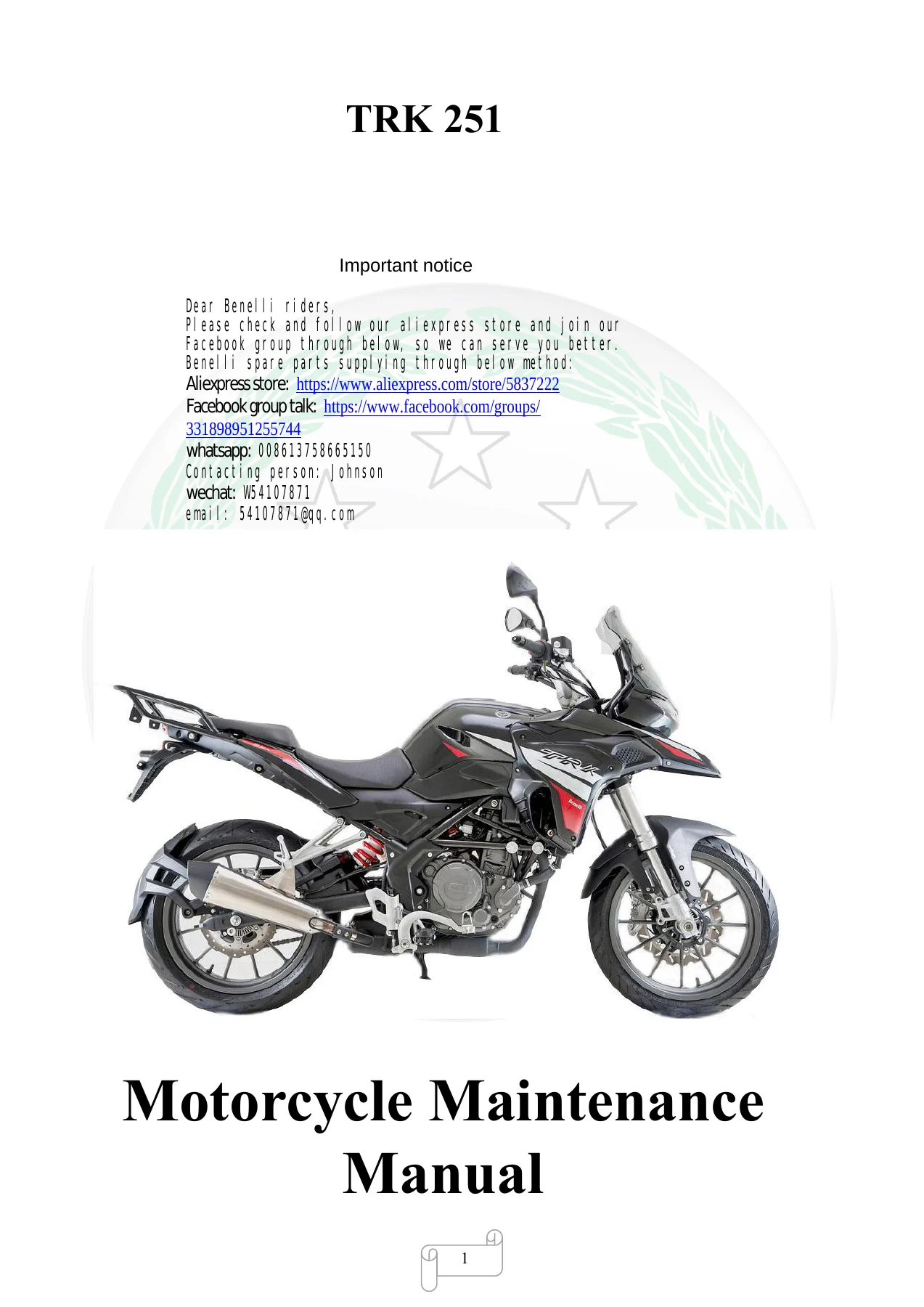
Benelli TRK 251 BJ250-18 Service Manual - Complete Workshop Repair Guide β€” PDF page 1 preview
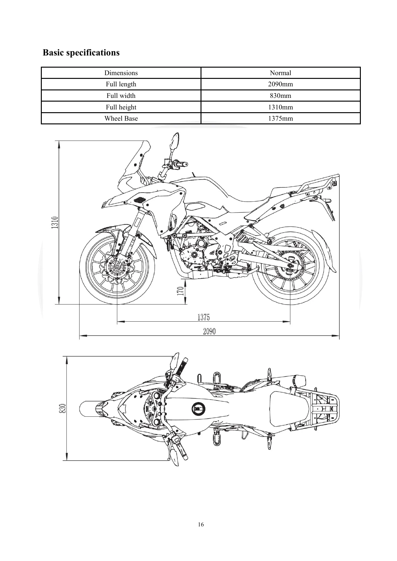
Benelli TRK 251 BJ250-18 Service Manual - Complete Workshop Repair Guide β€” PDF page 38 preview
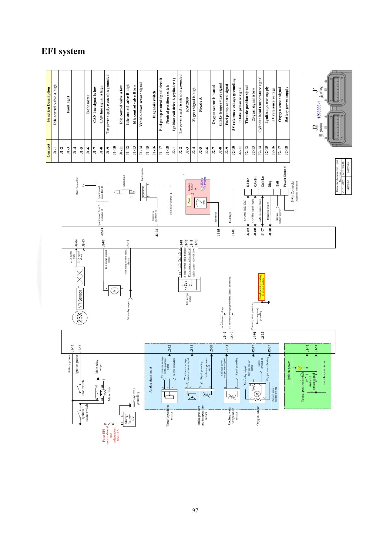
Benelli TRK 251 BJ250-18 Service Manual - Complete Workshop Repair Guide β€” PDF page 119 preview

This manual is delivered as an instant PDF download. There is no shipping, no waiting for a physical book, and no restrictions on how many times you print or view it. You can access it on any device β€” laptop, tablet, or smartphone β€” and print only the pages you need for the job at hand. Whether you are a professional mechanic or a dedicated owner who prefers to maintain their own motorcycle, this Benelli TRK 251 workshop manual gives you the information to do the job right.
Reviews

There are no reviews yet.

Be the first to review “Benelli TRK 251 BJ250-18 Service Manual – Complete Workshop Repair Guide”

What Our Customers Say

β˜…β˜…β˜…β˜…β˜… Live reviews from customers
Loading customer reviews...
0
    0
    Your Cart
    Your cart is emptyReturn to Shop
    πŸ›’
    Recently Purchased
    πŸ•’ verified order