★ TRUSTED BY 321,897+ PROFESSIONALS WORLDWIDE
🏢
Trusted Business
Verified & Licensed
🛡️
Virus Free Files
100% Safe Downloads
🔒
Secure Payment
SSL Protected
Instant Delivery
Available Immediately
Sale!

Bobcat 425 Excavator Service Manual (2007) – PDF Repair & Maintenance Guide 6904866

Original price was: $39.95.Current price is: $24.95.

Complete 726-page Bobcat 425 Excavator Service Manual, publication 6904866, revision 425-1 dated 15 July 2007. Covers Standard Arm and Long Arm machines from serial A1HW11001 and above – hydraulics, undercarriage, upperstructure, electrical, engine service, heater and full specifications in one instant PDF download.

Instant PDF Download
Available immediately
💾
Save to Your Device
Download & keep forever
🛡️
Antivirus Scanned
100% virus-free
🌍
Trusted Worldwide
175,000+ customers

Description

Bobcat 425 Excavator Service Manual (2007) – Complete PDF Repair & Maintenance Guide

This is the full Bobcat 425 Excavator Service Manual, publication number 6904866, issued under Revision No. 425-1 and dated 15 July 2007. It is the shop-level reference for the 425 compact excavator in both Standard Arm and Long Arm Option configurations, and it applies to machines from serial number A1HW11001 and above. Everything is contained in a single 726-page English-language document, divided into eight numbered sections that run from routine maintenance through hydraulic valve overhaul, undercarriage rebuild, electrical diagnosis and complete engine teardown.

The Bobcat 425 Excavator Service Manual is written for the person actually doing the work: it pairs step-by-step removal and installation procedures with disassembly and assembly sequences, torque figures, testing methods, adjustment values and troubleshooting charts. Whether you are chasing a slow swing circuit, resealing a boom cylinder, resetting track tension or pulling the Kubota engine apart, this manual gives you the procedure and the numbers to do it correctly the first time.

File Details

  • Manual type: Service / repair manual
  • Brand: Bobcat
  • Model: 425 Excavator (Standard Arm and Long Arm Option)
  • Document number: 6904866 (11-06)
  • Revision: 425-1, dated 15 July 2007
  • Serial coverage: A1HW11001 and above
  • Language: English
  • Page count: 726 pages
  • Format: PDF

IMAGES PREVIEW

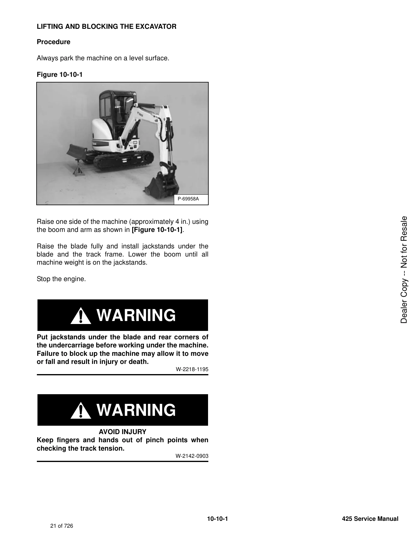
Bobcat 425 Excavator Service Manual (2007) - PDF Repair & Maintenance Guide 6904866 — PDF page 21 preview
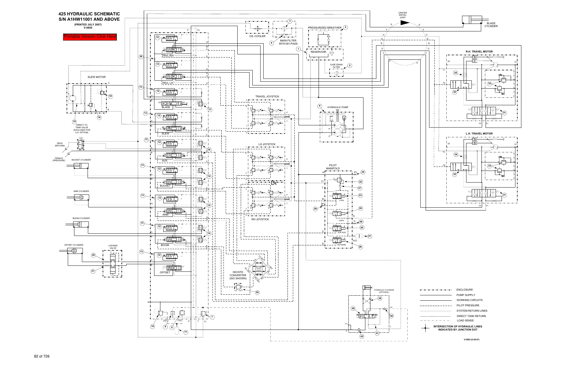
Bobcat 425 Excavator Service Manual (2007) - PDF Repair & Maintenance Guide 6904866 — PDF page 82 preview
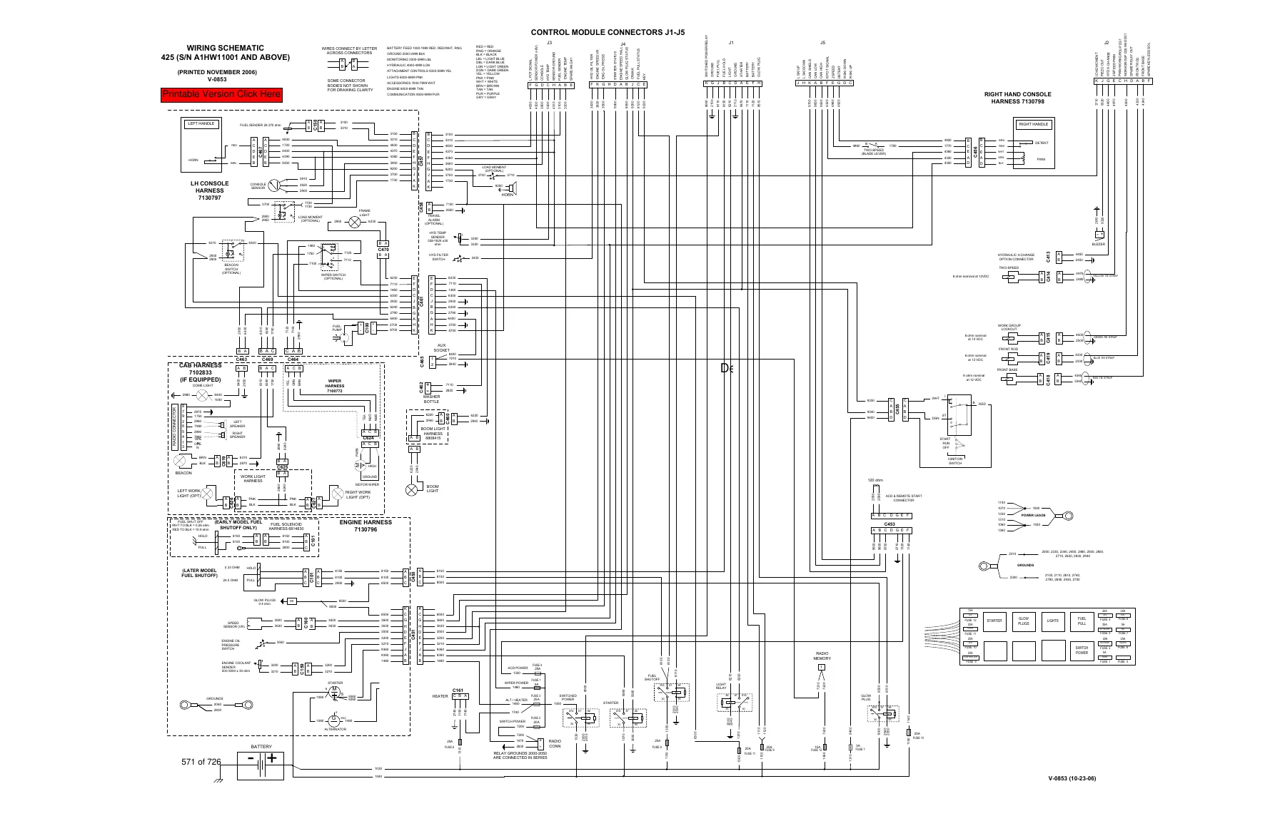
Bobcat 425 Excavator Service Manual (2007) - PDF Repair & Maintenance Guide 6904866 — PDF page 571 preview

Chapters Covered

  • Safety and Maintenance (Section 10) – daily check, service schedule, air cleaner service, engine cooling system, engine lubrication system, fuel system, hydraulic system, lifting and blocking the excavator, lubricating the excavator, excavator storage and return to service
  • Hydraulic System (Section 20) – hydraulic system information and troubleshooting, main relief valve, port relief valves, crossport relief valves, pressure reducing valve, hydraulic control valve, hydraulic pump, manifold assembly / accumulator, travel motor, swing motor, swing motor drive carrier, swivel joint, control pattern selector valve, left and right control levers (joysticks), travel control valve, hydraulic filter, case drain filter, hydraulic reservoir, oil cooler, direct to tank valve, non-pressurized accumulator, hydraulic X-Change valve
  • Undercarriage (Section 30) – blade, track frame components, checking and adjusting track tension, rubber track removal and installation, steel track removal and installation, front idler, track rollers, track guide, swing circle gear
  • Upperstructure & Swing Section (Section 40) – upperstructure removal and installation, canopy, cab, seat and seat mount, right console, left console, blade control, upperstructure slew lock, floor mat and floor panels, boom swing pedal, travel lever / pedals, fuel tank, horn, swing frame, boom, arm, bucket, tailgate, X-Change, right and left side covers, counterweight
  • Electrical System and Analysis (Section 50) – electrical system information, battery, alternator, starter, lights, magnetic lockout sensor, fuel level sender, diagnostic service codes
  • Engine Service (Section 60) – engine information, engine speed control, spark arrestor muffler, air cleaner, engine cooling system, lubrication system, fuel system, cylinder head, crankshaft and pistons, camshaft and timing gears, flywheel and housing
  • Heater (Section 70) – heater system, regular maintenance, troubleshooting, heater unit, heater coil, blower fan, heater valve
  • Specifications (SPEC) – excavator specifications, torque specifications for bolts, hydraulic connection specifications, hydraulic fluid specifications, conversions

Read as a whole, this Bobcat 425 Excavator Service Manual functions as a single-source technical library for one machine. The hydraulic section alone walks through the closed-centre control valve section by section – inlet, right travel, left travel, blade, slew, auxiliary, bucket, arm, boom, boom swing and outlet – with the gasket, O-ring, spool, spring and compensator details for each. The engine portion covers the Kubota four-cylinder diesel down to cylinder head disassembly, valve clearance adjustment, injection pump timing, piston ring gap measurement, crankshaft bearing clearances and flywheel housing removal. Electrical coverage includes the fuse and relay layout, harness connector identification, alternator and starter test routines, and a full diagnostic service code list. It is the kind of manual you keep on the bench rather than the shelf.

What This Bobcat 425 Service Manual Lets You Do

  • Run the correct daily, 50-hour, 100-hour, 250-hour, 500-hour and 1000-hour service schedule on a 425 excavator
  • Test and adjust the main relief valve, port relief valves and crossport relief valves with the specified target pressures and acceptable ranges
  • Remove, disassemble, inspect, reseal and reassemble the boom, arm, bucket, boom swing and blade cylinders, including torque values for the piston nut and head
  • Troubleshoot the hydraulic circuit, cylinder circuit, swing circuit and travel circuit using the dedicated troubleshooting charts
  • Remove and install the hydraulic pump, travel motors, swing motor, swing motor drive carrier and swivel joint
  • Take apart and rebuild the hydraulic control valve section by section
  • Diagnose electrical faults using the wiring schematic and the diagnostic service code list
  • Remove, disassemble and reassemble the engine, cylinder head, crankshaft, pistons, camshaft and timing gears
  • Check and adjust track tension on both rubber and steel tracks, and remove or install the track assemblies
  • Remove and install the upperstructure, boom, arm, bucket, swing frame, counterweight, cab and canopy

Complete PDF Bookmark Tree

Complete Bookmarks

The complete bookmarks in the “Bobcat 425 Excavator Service Manual (2007) – PDF Repair & Maintenance Guide 6904866” are as follows:

MAINTENANCE SAFETYp. 3
ALPHABETICAL INDEXp. 5
CONTENTSp. 7
FOREWORDp. 9
SAFETY INSTRUCTIONSp. 11
Fire Preventionp. 13
SERIAL NUMBER LOCATIONSp. 15
Excavator Serial Numberp. 15
Engine Serial Numberp. 15
DELIVERY REPORTp. 16
EXCAVATOR IDENTIFICATIONp. 17
SAFETY AND MAINTENANCEp. 19
LIFTING AND BLOCKING THE EXCAVATORp. 21
Procedurep. 21
UPPERSTRUCTURE SLEW LOCKp. 23
Operationp. 23
LIFTING THE EXCAVATORp. 25
Procedurep. 25
OPERATOR CAB (ROPS / TOPS)p. 27
Descriptionp. 27
Cab Doorp. 27
Front Windowp. 28
Front Wiperp. 29
Window Washer Reservoirp. 29
Right Side Windowp. 30
Heating, Ventilation, and Air Conditioning Ductp. 31
TRANSPORTING THE EXCAVATOR ON A TRAILERp. 33
Loading And Unloadingp. 33
Fasteningp. 33
TAILGATEp. 35
Opening And Closingp. 35
RIGHT SIDE COVERp. 37
Opening And Closingp. 37
SERVICE SCHEDULEp. 39
Chartp. 39
AIR CLEANER SERVICEp. 41
Daily Checkp. 41
Replacing Filter Elementsp. 41
ENGINE COOLING SYSTEMp. 43
Cleaningp. 43
Checking Levelp. 44
Removing And Replacing Coolantp. 45
FUEL SYSTEMp. 47
Fuel Specificationsp. 47
Filling The Fuel Tankp. 47
Fuel Filtersp. 48
Draining The Fuel Tankp. 50
Removing Air From The Fuel Systemp. 50
ENGINE LUBRICATION SYSTEMp. 51
Checking And Adding Engine Oilp. 51
Engine Oil Chartp. 51
Removing And Replacing Oil Filterp. 52
HYDRAULIC SYSTEMp. 53
Checking And Adding Fluidp. 53
Hydraulic Fluid Chartp. 53
Removing And Replacing The Hydraulic Filterp. 54
Removing And Replacing The Case Drain Filterp. 54
Removing And Replacing The Hydraulic Fluidp. 55
LUBRICATING THE EXCAVATORp. 57
Lubrication Locationsp. 57
TRAVEL MOTORp. 61
Checking And Adding Oilp. 61
Removing And Replacing Oilp. 61
SPARK ARRESTOR MUFFLERp. 63
Cleaning Procedurep. 63
ALTERNATOR BELTp. 65
Belt Adjustmentp. 65
Belt Replacementp. 65
SEAT BELTp. 67
Inspection And Maintenancep. 67
PIVOT PINSp. 69
Inspection And Maintenancep. 69
EXCAVATOR STORAGE AND RETURN TO SERVICEp. 71
Storagep. 71
Return to Servicep. 71
STOPPING THE ENGINE AND LEAVING THE EXCAVATORp. 73
Procedurep. 73
Emergency Exitsp. 74
HYDRAULIC SYSTEMp. 75
HYDRAULIC/HYDROSTATIC SCHEMATIC
HYDRAULIC SYSTEM INFORMATIONp. 83
Glossary Of Hydraulic / Hydrostatic Symbolsp. 83
Troubleshooting The Hydraulic Circuitp. 87
Troubleshooting The Cylinder Circuitp. 88
Troubleshooting The Swing (Upperstructure Slew) Circuitp. 89
Troubleshooting The Travel Circuitp. 90
BOOM CYLINDERp. 91
Testingp. 91
Removal And Installationp. 94
Parts Identificationp. 97
Disassemblyp. 98
Assemblyp. 100
ARM CYLINDERp. 103
Testingp. 103
Removal And Installationp. 105
Parts Identificationp. 107
Disassemblyp. 108
Assemblyp. 110
BOOM SWING CYLINDERp. 113
Testingp. 113
Removal And Installationp. 115
Parts Identificationp. 116
Disassemblyp. 117
Assemblyp. 119
BUCKET CYLINDERp. 123
Testingp. 123
Removal And Installationp. 125
Parts Identificationp. 126
Disassemblyp. 127
Assemblyp. 129
BLADE CYLINDERp. 133
Testingp. 133
Removal And Installationp. 135
Parts Identificationp. 136
Disassemblyp. 137
Assemblyp. 139
MAIN RELIEF VALVEp. 143
Testing And Adjusting The Main Relief Valvep. 143
PORT RELIEF VALVESp. 147
Testing And Adjusting Port Relief Valve Pressurep. 147
CROSSPORT RELIEF VALVESp. 149
Testing And Adjusting The Crossport Relief Valvesp. 149
PRESSURE REDUCING VALVEp. 153
Testing And Adjusting The Pressure Reducing Valvep. 153
HYDRAULIC CONTROL VALVEp. 155
Descriptionp. 155
Removal And Installationp. 156
Parts Identificationp. 159
Disassemblyp. 160
Right Travel Valve Section Disassembly And Assemblyp. 162
Left Travel Valve Section Disassembly And Assemblyp. 166
Blade Valve Section Disassembly And Assemblyp. 170
Slew Valve Section Disassembly And Assemblyp. 179
Auxiliary Valve Section Disassembly And Assemblyp. 184
Bucket Valve Section Disassembly And Assemblyp. 189
Arm Valve Section Disassembly And Assemblyp. 194
Boom Valve Section Disassembly And Assemblyp. 199
Boom Swing Valve Section Disassembly And Assemblyp. 204
Inlet Section Disassembly And Assemblyp. 209
Assemblyp. 214
HYDRAULIC PUMPp. 221
Descriptionp. 221
Torque Adjustmentp. 222
Testing The Piston Pumpp. 223
Testing Auxiliary Hydraulic Flowp. 224
Removalp. 225
Installationp. 226
Coupler Removal And Installationp. 227
Parts Identification (Piston Pump)p. 228
Disassemblyp. 229
Piston Pump Disassemblyp. 230
Piston Pump Assemblyp. 236
Assemblyp. 242
MANIFOLD ASSEMBLY / ACCUMULATORp. 243
Descriptionp. 243
Removal And Installationp. 243
Parts Identificationp. 245
Disassembly And Assemblyp. 246
TRAVEL MOTORp. 255
Descriptionp. 255
Removal And Installationp. 255
Parts Identificationp. 256
Disassemblyp. 257
Assemblyp. 267
SWIVEL JOINTp. 279
Descriptionp. 279
Removal And Installationp. 279
Parts Identificationp. 281
Disassemblyp. 282
Assemblyp. 283
SWING MOTORp. 287
Descriptionp. 287
Removal And Installationp. 287
Parts Identificationp. 289
Disassemblyp. 290
Assemblyp. 295
SWING MOTOR DRIVE CARRIERp. 301
Descriptionp. 301
Removal And Installationp. 301
Parts Identificationp. 302
Disassemblyp. 303
Assemblyp. 305
CONTROL PATTERN SELECTOR VALVEp. 309
Descriptionp. 309
Removal And Installationp. 309
Parts Identificationp. 310
Disassembly and Assemblyp. 311
RIGHT CONTROL LEVER (JOYSTICK)p. 313
Descriptionp. 313
Testingp. 313
Handle Removal And Installationp. 314
Removal And Installationp. 318
Parts Identificationp. 321
Disassemblyp. 322
Assemblyp. 327
LEFT CONTROL LEVER (JOYSTICK)p. 333
Descriptionp. 333
Testingp. 333
Handle Removal And Installationp. 334
Removal And Installationp. 337
Parts Identificationp. 339
Disassemblyp. 340
Assemblyp. 345
TRAVEL CONTROL VALVEp. 351
Removal and Installationp. 351
Parts Identificationp. 352
Disassembly And Assemblyp. 353
HYDRAULIC FILTERp. 357
Descriptionp. 357
Housing Removal And Installationp. 357
CASE DRAIN FILTERp. 359
Descriptionp. 359
Removal And Installationp. 359
HYDRAULIC RESERVOIRp. 361
Descriptionp. 361
Removal And Installationp. 361
OIL COOLERp. 363
Descriptionp. 363
Removal And Installationp. 363
DIRECT TO TANK VALVEp. 365
Desciptionp. 365
Removal And Installationp. 365
Parts Identificationp. 366
Disassembly And Assemblyp. 367
NON-PRESSURIZED ACCUMULATORp. 369
Desciptionp. 369
Removal And Installationp. 369
HYDRAULIC X-CHANGE VALVEp. 371
Removal And Installationp. 371
Parts Identificationp. 373
Disassemblyp. 374
Assemblyp. 382
UNDERCARRIAGEp. 391
BLADEp. 393
Descriptionp. 393
Removal And Installationp. 393
TRACK FRAME COMPONENTSp. 395
Descriptionp. 395
Track Lug Heightp. 395
Checking Tensionp. 396
Adjusting Tensionp. 397
Rubber Track Removal And Installationp. 399
Steel Track Removal And Installationp. 402
Idler (Front) Removal And Installationp. 405
Idler (Front) Parts Identificationp. 406
Idler (Front) Disassemblyp. 407
Idler (Front) Assemblyp. 409
Coil Spring Assembly And Cylinder Disassembly And Assemblyp. 412
Roller Removal and Installationp. 413
Roller Parts Identificationp. 414
Roller Disassemblyp. 415
Roller Assemblyp. 417
Track Guide Removal And Installationp. 419
Track Damage Identificationp. 420
SWING CIRCLE GEARp. 431
Removal And Installationp. 431
UPPERSTRUCTURE & SWING SECTIONp. 433
UPPERSTRUCTUREp. 437
Descriptionp. 437
Removalp. 437
Installationp. 440
CANOPYp. 443
Removal And Installationp. 443
CABp. 447
Removal And Installationp. 447
Door Removal And Installationp. 452
Front Window Removal And Installationp. 453
Right Side Rear Sliding Window Removal And Installationp. 456
Right Side Front Sliding Window Removal And Installationp. 456
Glass Removalp. 457
Right Side Front And Rear Sliding Window Weather Strip Removal And Installationp. 458
Right Side Front And Rear Sliding Window Wiper Strip Removal And Installationp. 458
Glass Installationp. 459
SEAT AND SEAT MOUNTp. 465
Seat Mount Removal And Installationp. 465
Seat Removal And Installationp. 466
RIGHT CONSOLEp. 467
Descriptionp. 467
Console Cover Removal And Installationp. 467
Console Base Cover Removal And Installationp. 468
LEFT CONSOLEp. 471
Descriptionp. 471
Joystick Console Cover (Bottom) Removal And Installationp. 471
Joystick Console Cover (Top) Removal And Installationp. 472
Compression Spring Removal And Installationp. 473
Compression Spring Disassembly And Assemblyp. 473
Lever Removal And Installationp. 475
Joystick Console Frame Removal And Installationp. 477
Joystick Console Frame Disassembly And Installationp. 478
Left Rear Console Cover Removal And Installationp. 479
Left Rear Console Frame Removal And Installationp. 480
Left Rear Console Frame Disassembly And Assemblyp. 482
BLADE CONTROLp. 483
Removal And Installationp. 483
Disassembly And Assemblyp. 483
Linkage Removal And Installationp. 484
Linkage Disassembly And Assemblyp. 486
UPPERSTRUCTURE SLEW LOCKp. 487
Removal and Installationp. 487
FLOOR MAT AND FLOOR PANELp. 489
Descriptionp. 489
Removal And Installationp. 489
BOOM SWING PEDALp. 493
Descriptionp. 493
Removal And Installationp. 493
Disassembly And Assemblyp. 494
Linkage Removal And Installationp. 496
TRAVEL LEVER / PEDALSp. 497
Descriptionp. 497
Removal And Installationp. 497
Disassembly And Assemblyp. 498
Adjustmentp. 500
Linkage Removal And Installationp. 502
FUEL TANKp. 503
Removal And Installationp. 503
HORNp. 507
Removal And Installationp. 507
SWING FRAMEp. 509
Descriptionp. 509
Removal And Installationp. 509
Hose Routingp. 513
Bushing Removal And Installationp. 514
Swing Frame Bushing Removal And Installationp. 514
BOOMp. 517
Descriptionp. 517
Removal And Installationp. 517
ARMp. 521
Descriptionp. 521
Removal And Installationp. 521
Arm To Boom Bushing Removal And Installationp. 522
Arm To Bucket And Bucket Link Bushing Removal And Installationp. 522
BUCKETp. 525
Removal And Installation (Pin-On X-Change)p. 525
Removal And Installation (Bolt-On X-Change)p. 531
Removal And Installation (Pin-On Attachment)p. 537
Bucket Teeth Removal And Installationp. 538
Bucket Side Cutting Edge Removal And Installationp. 539
TAILGATEp. 541
Removal And Installationp. 541
Latch Removal And Installationp. 541
X-CHANGEp. 543
Pin-On Removal And Installationp. 543
Pin-On Disassembly and Assemblyp. 544
X-CHANGE (HYDRAULIC)p. 545
Removal And Installationp. 545
Parts Identificationp. 548
Disassemblyp. 549
Assemblyp. 554
RIGHT SIDE COVERp. 563
Removal And Installationp. 563
Latch Removal And Installationp. 563
COUNTERWEIGHTp. 565
Descriptionp. 565
Removal And Installation (Long Arm Counterweight)p. 565
Removal And Installation (Standard Counterweight)p. 566
LEFT SIDE COVERp. 567
Removal And Installationp. 567
ELECTRICAL SYSTEM AND ANALYSISp. 569
ELECTRICAL SCHEMATICS
ELECTRICAL SYSTEM INFORMATIONp. 573
Glossary Of Electrical Symbolsp. 573
Harness Connectorsp. 576
Troubleshootingp. 578
Descriptionp. 579
Fuse And Relay Location / Identificationp. 579
BATTERYp. 581
Removal And Installationp. 581
Servicingp. 582
Using A Booster Battery (Jump Starting)p. 583
ALTERNATORp. 585
Belt Adjustmentp. 585
Belt Replacementp. 585
Charging System Inspectionp. 586
Descriptionp. 587
Testsp. 587
Alternator Output Testp. 588
Full Field Testp. 588
Alternator Regulator Testp. 589
Alternator Regulator Test With Voltmeterp. 589
Removal And Installationp. 590
Parts Identificationp. 591
STARTERp. 593
Testingp. 593
Removal And Installationp. 594
Parts Identificationp. 595
LIGHTSp. 597
Upperstructure Light Removal And Installationp. 597
Upperstructure Light Disassembly And Assemblyp. 597
Boom Light Removal And Installationp. 598
Boom Light Disassembly And Assemblyp. 598
MAGNETIC LOCKOUT SENSORp. 599
Testing Left Console Magnetic Lockout Sensorp. 599
Left Console Magnetic Lockout Sensor Removal And Installationp. 600
FUEL LEVEL SENDERp. 603
Removal And Installationp. 603
Testingp. 604
DIAGNOSTIC SERVICE CODESp. 605
Descriptionp. 605
Service Codes Listp. 606
ENGINE SERVICEp. 607
ENGINE INFORMATIONp. 609
Descriptionp. 609
Specificationsp. 610
Torque Valuesp. 614
Troubleshootingp. 615
Removal And Installationp. 616
Engine Mount Replacementp. 620
Compression – Checkingp. 621
ENGINE SPEED CONTROLp. 623
Removal And Installationp. 623
SPARK ARRESTOR MUFFLERp. 625
Removal And Installationp. 625
AIR CLEANERp. 627
Removal And Installationp. 627
ENGINE COOLING SYSTEMp. 629
Radiator Removal And Installationp. 629
Radiator Disassembly and Assemblyp. 631
Water Pump Removal And Installationp. 631
Water Pump Disassembly And Assemblyp. 632
Thermostat Housing Removal And Installationp. 632
Testing The Thermostatp. 633
LUBRICATION SYSTEMp. 635
Oil Pan Removal And Installationp. 635
Oil Pump Removal And Installationp. 635
Oil Pump Inspectionp. 636
Engine Oil Pressure – Testingp. 637
FUEL SYSTEMp. 639
Fuel Camshaft Removal And Installationp. 639
Fuel Camshaft Governor Disassembly And Assemblyp. 639
Fuel Shutoff Solenoid – Checkingp. 640
Fuel Shutoff Solenoid Removal And Installationp. 641
Fuel Injection Pump Removal And Installationp. 642
Timing The Injection Pumpp. 644
Fuel Injector Removal And Installationp. 646
Fuel Injector Nozzles Pressure – Checkingp. 648
Nozzle Spray Conditionp. 649
Valve Seat Tightnessp. 649
CYLINDER HEADp. 651
Glow Plug – Testingp. 651
Glow Plug Removal And Installationp. 652
Valve Clearance Adjustmentp. 652
Valve Timing – Checkingp. 653
Cylinder Head Removal And Installationp. 654
Cylinder Head Disassembly and Assemblyp. 656
Cylinder Head – Servicingp. 656
Cylinder Head Top Clearancep. 657
Valve Guide – Checkingp. 657
Reconditioning The Valve And Valve Seatp. 658
Valve Springp. 660
Valve Tappetsp. 661
Rocker Arm And Shaft – Checkingp. 661
CRANKSHAFT AND PISTONSp. 663
Piston And Connecting Rod Removal And Installationp. 663
Piston And Connecting Rod – Servicingp. 665
Cylinder Bore Checkingp. 667
Connecting Rod Alignmentp. 668
Crankshaft And Bearings Removal And Installationp. 668
Crankshaft And Bearings – Servicingp. 670
CAMSHAFT AND TIMING GEARSp. 675
Timing Gearcase Cover Removal And Installationp. 675
Timing Gears Backlash – Checkingp. 677
Idler Gear And Shaft Removal And Installationp. 677
Camshaft – Servicingp. 678
Idler Gear And Shaft Servicingp. 680
FLYWHEEL AND HOUSINGp. 681
Flywheel Housing Removal And Installationp. 681
Hydraulic Pump Coupler Removal And Installationp. 682
Flywheel Removal And Installationp. 683
Rear End Plate Removal And Installationp. 683
HEATERp. 685
HEATER SYSTEMp. 687
Descriptionp. 687
Componentsp. 687
REGULAR MAINTENANCEp. 689
Filter Element Removal And Installationp. 689
Heater Coilp. 690
TROUBLESHOOTINGp. 691
Blower Motor Does Not Operatep. 691
Blower Motor Operates Normally, But Air Flow Is Insufficientp. 691
Electrical Systemp. 692
HEATER UNITp. 697
Removal And Installationp. 697
HEATER COILp. 699
Removal And Installationp. 699
BLOWER FANp. 701
Removal And Installationp. 701
HEATER VALVEp. 703
Removal And Installationp. 703
SPECIFICATIONSp. 705
EXCAVATOR SPECIFICATIONSp. 707
425 With Standard Armp. 707
425 With Long Arm Optionp. 709
Performancep. 711
Controlsp. 711
Enginep. 711
Hydraulic Systemp. 712
Hydraulic Cylindersp. 712
Hydraulic Cycle Timesp. 712
Electricalp. 712
Instrumentationp. 712
Drive Systemp. 713
Slew Systemp. 713
Undercarriagep. 713
Crawler Track Designp. 713
Capacitiesp. 713
Fuel Tankp. 713
Tracksp. 713
Typep. 713
Ground Pressurep. 713
TORQUE SPECIFICATIONS FOR BOLTSp. 715
Torque For General SAE Boltsp. 715
Torque For General Metric Boltsp. 716
HYDRAULIC CONNECTION SPECIFICATIONSp. 717
O-ring Face Seal Connectionp. 717
Straight Thread O-ring Fittingp. 718
Tubelines And Hosesp. 718
Flare Fittingp. 719
Port Seal Fittingp. 720
HYDRAULIC FLUID SPECIFICATIONSp. 721
Specificationsp. 721
CONVERSIONSp. 723
Decimal And Millimeter Equivalentsp. 723
U.S. To Metric Conversion Chartp. 723
SMR
425-1

Specifications and Reference Data Included

Because this is the full shop manual rather than a condensed owner’s guide, it also carries the reference data a technician reaches for mid-job: torque specifications for general SAE and metric bolts, hydraulic connection tightening torques for O-ring face seal, straight thread O-ring, flare and port seal fittings, engine torque values, service limits and clearances for valves, pistons, rings, crankshaft journals and bearings, hydraulic cylinder bore and stroke data, system relief pressures for both the Standard Arm and Long Arm machines, and full excavator specifications for operating weight, digging force, travel speed, pump capacity and capacities. The hydraulic schematic and the wiring schematic for the 425 (serial A1HW11001 and above) are reproduced in the document as well.

Who This Bobcat 425 Excavator Service Manual Is For

This manual suits independent excavator mechanics, fleet maintenance departments, owner-operators who service their own 425, and anyone rebuilding a hydraulic or engine component on the bench. It is equally useful as a reference for setting up a machine after major repair, checking that relief pressures and clearances are back within specification, and confirming torque values before final assembly. If your machine falls outside serial A1HW11001 and above, the procedures may still apply but component differences are possible – always confirm by serial number before ordering parts or following a specific service operation.

Why Correct Procedures and Specifications Matter on a 425

Compact excavators run tight hydraulic tolerances and high system pressures. Guessing at a relief valve setting, reusing a damaged O-ring, or torquing a cylinder nut to the wrong figure can turn a straightforward reseal into a repeat failure – or worse, damage the pump. The Bobcat 425 Excavator Service Manual removes the guesswork by giving the exact procedure, the correct sequence, the target pressure and the acceptable range for the job in front of you. That is the difference between a repair that holds and one that comes back.

Instant PDF Delivery

The Bobcat 425 Excavator Service Manual 6904866 is delivered as a digital PDF the moment your order is complete – no shipping, no waiting, no physical book to lose in the shop. Open it on a laptop, tablet or phone at the machine, print only the pages you need for the job, and keep the full 726-page document on file for every future repair. One download covers the whole machine.
Reviews

There are no reviews yet.

Be the first to review “Bobcat 425 Excavator Service Manual (2007) – PDF Repair & Maintenance Guide 6904866”

What Our Customers Say

★★★★★ Live reviews from customers
Loading customer reviews...
0
    0
    Your Cart
    Your cart is emptyReturn to Shop
    🛒
    Recently Purchased
    🕒 verified order