Description
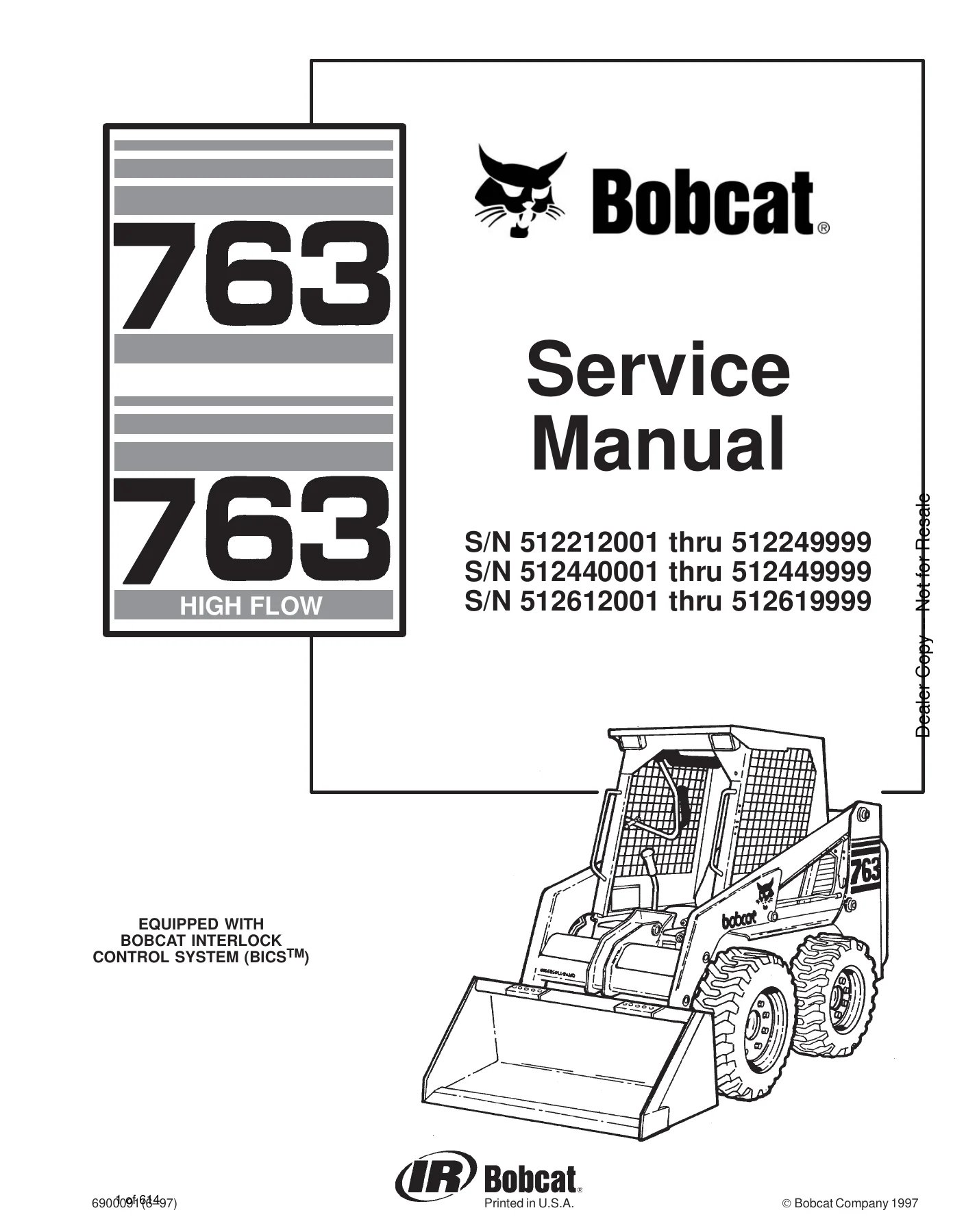
Bobcat 763 & 763 High Flow Skid-Steer Loader Service Manual – Publication 6900091
This is the full workshop service manual for the Bobcat 763 and 763 High Flow (763H) skid-steer loaders, Bobcat publication number 6900091. It is the manual a technician opens when the machine needs a hydraulic pump torn down, a hydrostatic drive motor timed, a final drive chain replaced, a Kubota V2203E engine rebuilt, or an Advanced Hand Control fault isolated. At 614 pages it covers every major system on the loader, from the control valve stack to the chaincase and the BICS interlock wiring, with the torque values, service limits and step-by-step procedures written out in full.
File Details
- Manual type: Skid-Steer Loader Service Manual (shop/repair)
- Brand: Bobcat
- Models covered: 763, 763 High Flow (763H)
- Publication number: 6900091
- Edition/date: Original 1997 printing, revised through January 2002
- Language: English
- Page count: 614 pages
- File format: PDF
- Serial number coverage: S/N 512212001 thru 512249999, S/N 512440001 thru 512449999, S/N 512612001 thru 512619999
Chapters Covered
The Bobcat 763 / 763H service manual is divided into ten numbered sections plus a full alphabetical index. The top-level contents are:
- Preventive Maintenance – Service schedule, lifting and blocking, towing, transporting, stopping the loader, lift arm support device, operator cab raising/lowering, seat bar restraint systems (foot pedal, mechanical hand control and advanced hand control versions), lubrication, air cleaner, alternator belt, drive belt (spring-loaded and fixed idler versions), engine cooling, engine lubrication, fan gearbox, final drive chaincase, fuel system, hydraulic/hydrostatic fluid and filters, reservoir breather cap, spark arrestor muffler, tire maintenance, Bob-Tach, remote start switch
- Hydraulic System – Hydraulic system information, troubleshooting, lift and tilt cylinder service, hydraulic cylinder disassembly and assembly, control valve (both early and late serial ranges), BICS valve, main relief valve, hydraulic pump (including 763H high flow pump), hydraulic filter housing, hydraulic fluid reservoir, control pedals, select valve (763H), pedal interlock linkage, lift lock by-pass valve, tilt lock valve
- Hydrostatic System – Hydrostatic system information, charge pressure checking, replenishing valve function, troubleshooting, hydrostatic drive motor (early and 30 Series), hydrostatic pump, drive belt housing, spring-loaded and fixed drive belt tensioner pulleys, oil cooler
- Drive System – Parking brake, parking brake disc, traction lock guides, chaincase fluid and covers, motor carrier, axle seal, axle, sprocket and bearings, drive chain
- Main Frame – Bob-Tach, fuel tank and level sender, lift arms, operator cab, cab gas cylinder, operator seat, rear grill, rear door, rear lights, seat bar (gas cylinder and compression spring versions)
- Electrical System – Electrical system information, fuse location, troubleshooting, battery, alternator tests and disassembly, starter (Delco Remy and Denso versions), standard instrument panel, front lights, relay switches
- Engine Service – Engine removal and installation, engine mount replacement, engine speed control, radiator, muffler, blower housing/fan gearbox, air cleaner, flywheel, engine compression, glow plugs, fuel injection pump and timing, fuel injection nozzles, cylinder head, valves/seats/guides, valve clearance, rocker arm and shaft, timing gearcase cover, idler gear and camshaft, timing gears, fuel camshaft, crankshaft gear, oil pump, piston and connecting rod, crankshaft and bearings, cylinder bore, water pump
- Systems Analysis – Bobcat Interlock Control System (BICS) inspection and troubleshooting for both early and late serial ranges, BICS controller, seat and seat bar sensors, traction lock, Bobcat Operation Sensing System (BOSS) diagnostic tool, monitor service codes, operation sensing system unit, RPM sensor, sender and sensor service checks
- Specifications – Loader specifications, engine specifications, hydraulic connection specifications, torque specifications, standard torque for bolts, decimal and millimeter equivalents, US to metric conversion
- Advanced Hand Control System (AHC) – AHC components, troubleshooting, actuator voltage test, handle control unit test, AHC/PWM controller, control handle with push-button float, hydraulic control valve for AHC machines, BICS valve
In practical terms, this manual gives a technician the full workshop path through the loader. You can pull hydraulic flow and pressure readings on the gear pump and the 763H high flow pump, tear down and reseal a lift or tilt cylinder, rebuild the hydrostatic pump and time the drive motor, adjust the steering linkage to neutral, replace axle bearings and sprockets through the chaincase covers, set the Kubota V2203E valve clearances, time the injection pump with shims, and diagnose any BICS or AHC fault from the flashing-light codes. Every section that involves a torque value, a clearance, a service limit or a pressure specification carries that figure alongside the procedure, which is what separates this from a parts diagram or an owner’s booklet.
Complete PDF Bookmark Tree
Complete Bookmarks
The complete bookmarks in the “Bobcat 763 & 763 High Flow Skid-Steer Loader Service Manual 1997 – PDF Download” are as follows:
MAINTENANCE SAFETYp. 3
ALPHABETICAL INDEXp. 5
+CONTENTSp. 7
FOREWORDp. 9
SAFETY INSTRUCTIONSp. 11
FIRE PREVENTIONp. 12
SERIAL NUMBER LOCATIONSp. 13
LOADER SERIAL NUMBERp. 13
ENGINE SERIAL NUMBERp. 13
DELIVERY REPORTp. 13
BOBCAT LOADER IDENTIFICATIONp. 14
+PREVENTIVE MAINTENANCEp. 15
SERVICE SCHEDULEp. 17
+LIFTING AND BLOCKING THE LOADERp. 18
TRANSPORTING THE BOBCAT LOADERp. 19
TOWING THE LOADERp. 19
STOPPING THE BOBCAT LOADERp. 19
+LIFTING THE LOADERp. 20
+LIFT ARM SUPPORT DEVICEp. 21
Engaging The Lift Arm Support Devicep. 21
Disengaging The Lift Arm Support Devicep. 22
+OPERATOR CABp. 23
Descriptionp. 23
Emergency Exitp. 23
Raising The Operator Cabp. 24
Lowering The Operator Cabp. 25
+SEAT BAR RESTRAINT SYSTEM (Foot Pedals)p. 26
Descriptionp. 26
Seat Bar Inspectionp. 26
Seat Bar Maintenancep. 26
+SEAT BAR RESTRAINT SYSTEM (Mechanical Hand Controls)p. 27
Descriptionp. 27
Seat Bar Inspectionp. 27
Seat Bar Maintenancep. 27
+SEAT BAR RESTRAINT SYSTEM (Advanced Hand Controls)p. 28
Descriptionp. 28
Seat Bar Inspectionp. 28
Seat Bar Maintenancep. 28
+AIR CLEANER SERVICEp. 29
Replacing Filter Elementp. 29
+FUEL SYSTEMp. 31
Fuel Specificationsp. 31
Filling The Fuel Tankp. 31
Fuel Filterp. 31
Removing Air From The Fuel Systemp. 32
+ENGINE LUBRICATION SYSTEMp. 33
Checking Engine Oilp. 33
Oil Chartp. 33
Replacing Oil And Filterp. 33
+ENGINE COOLING SYSTEMp. 35
Cleaning The Cooling Systemp. 35
Checking The Coolant Levelp. 35
Replacing The Coolantp. 36
+ALTERNATOR BELTp. 37
Adjusting The Alternator Beltp. 37
+FAN GEARBOXp. 37
Checking And Maintainingp. 37
+HYDRAULIC/HYDROSTATIC SYSTEMp. 38
Checking And Adding Fluidp. 38
Replacing Hydraulic/Hydrostatic Filterp. 38
Replacing Hydraulic Fluidp. 39
Hydraulic Reservoir Breather Capp. 40
+SPARK ARRESTOR MUFFLERp. 41
+TIRE MAINTENANCEp. 42
Wheel Nutsp. 42
Tire Rotationp. 42
Tire Mountingp. 42
+FINAL DRIVE TRANSMISSION (CHAINCASE)p. 43
Checking And Adding Oilp. 43
Replacing Oil In The Chaincasep. 43
+DRIVE BELTp. 44
Adjusting The Drive Belt Equipped With The Spring Loaded Drive Idlerp. 44
Adjusting The Drive Belt Equipped With The Fixed Drive Idlerp. 46
Drive Belt Replacementp. 47
+LUBRICATION OF THE BOBCAT LOADERp. 48
+BOB–TACHp. 50
Inspection And Maintenancep. 50
+REMOTE START SWITCHp. 51
+HYDRAULIC SYSTEMp. 53
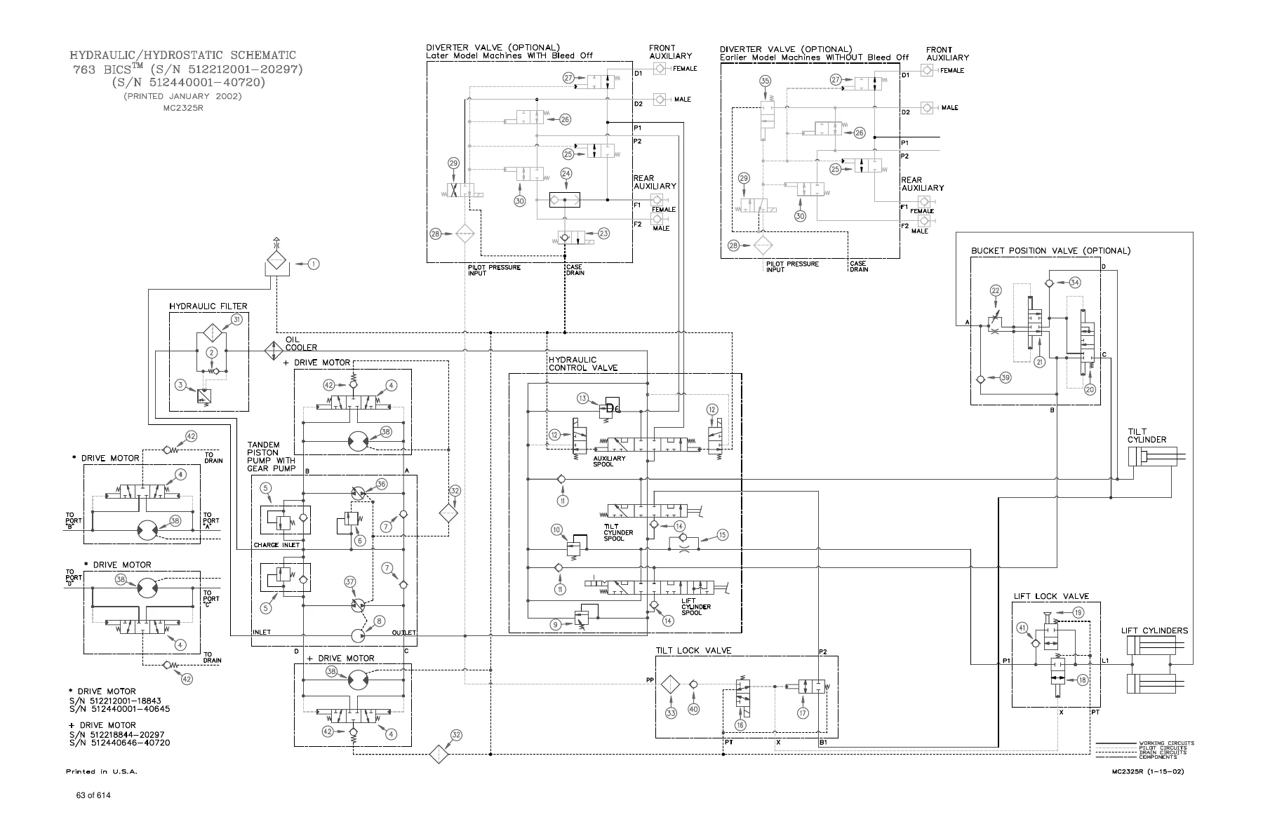
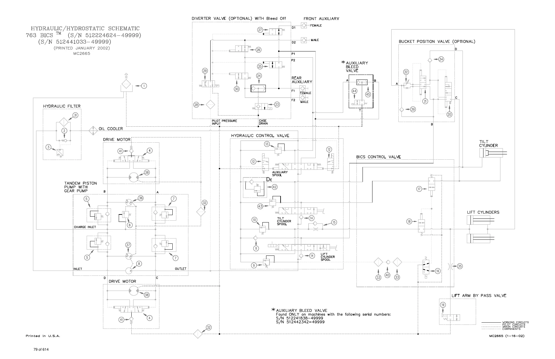
HYDRAULIC/HYDROSTATIC SCHEMATICSp. 57
TROUBLESHOOTINGp. 85
+HYDRAULIC SYSTEM INFORMATIONp. 86
Tightening Procedurep. 86
+LIFT CYLINDER(S)p. 87
Checking The Lift Cylinder(s) For Internal Leakagep. 87
Removal And Installationp. 87
+TILT CYLINDERp. 88
Checking The Tilt Cylinder For Internal Leakagep. 88
Removal And Installationp. 88
Rod End Seal Replacementp. 89
+HYDRAULIC CYLINDER IDENTIFICATIONp. 90
Lift Cylinder Componentsp. 90
Tilt Cylinder Componentsp. 91
+HYDRAULIC CYLINDERSp. 92
Disassemblyp. 92
Assemblyp. 94
+BICS™ VALVE (S/N 512220298 & Above, 512440721 & Above and 512612258 & Above)p. 100
Removalp. 100
Lift Arm By–Pass Orifice Disassemblyp. 101
Check Valve Disassemblyp. 101
Lock Valve Disassemblyp. 102
BICS™ Valve Solenoid Disassemblyp. 103
BICS™ Valve Solenoid Assemblyp. 104
Lock Valve Assemblyp. 105
Check Valve Assemblyp. 105
Lift Arm By–Pass Orifice Assemblyp. 106
Installationp. 107
+CONTROL VALVE (S/N 512220298 & Above, 512440721 & Above and 512612258 & Above)p. 108
Removal And Installationp. 108
Identification Chartp. 111
Disassemblyp. 112
Lift Base End Restrictor Disassemblyp. 112
Load Check Valve Disassemblyp. 112
Main Relief Valve Disassemblyp. 113
Port Relief Valve Disassemblyp. 114
Anti–Cavitation Valve Disassemblyp. 115
Rubber Boot Disassemblyp. 116
Lift Spool And Detent Disassemblyp. 117
Tilt Spool And Centering Spring Disassemblyp. 120
Auxiliary Spool Disassemblyp. 122
Auxiliary Electric Solenoid Disassemblyp. 123
Port–Auxiliary Section Disassemblyp. 124
Cleaning And Inspectionp. 124
Port–Auxiliary Section Assemblyp. 125
Auxiliary Electric Solenoid Assemblyp. 125
Auxiliary Spool Assemblyp. 126
Tilt Spool And Centering Spring Assemblyp. 127
Lift Spool And Detent Assemblyp. 129
Rubber Boot Assemblyp. 131
Anti–Cavitation Valve Assemblyp. 132
Port Relief Valve Assemblyp. 133
Main Relief Valve Assemblyp. 134
Load Check Valve Assemblyp. 134
Spool Seal Installationp. 136
+CONTROL VALVE (S/N 512220297 & Below,512440720 & Below and 512612257 & Below)p. 137
Removal And Installationp. 137
Identification Chartp. 140
Disassembly And Assemblyp. 141
Load Check Valvep. 141
Main Relief Valvep. 142
Port Relief Valvep. 142
Anti–Cavitation Valvep. 143
Rubber Bootp. 144
Lift Spool Detentp. 145
Tilt Centering Springp. 149
Auxiliary Spoolp. 150
Auxiliary Electric Solenoidp. 151
Plug/Port Relief Valvep. 152
Inspectionp. 152
Identification And Installation Of Spool Sealp. 153
+MAIN RELIEF VALVEp. 154
Checkingp. 154
Adjustmentp. 155
Removal And Installationp. 155
+HYDRAULIC PUMPp. 156
Removal And Installationp. 156
Checking The Output Of The Hydraulic Pumpp. 158
Checking The Output Of The High Flow Hydraulic Pump (763H)p. 160
Disassembly And Assemblyp. 161
Inspectionp. 163
Identificationp. 163
Removal And Installation (763H)p. 164
Identification (763H)p. 167
Disassembly And Assembly (763H)p. 168
+HYDRAULIC FILTER HOUSINGp. 171
Removal And Installationp. 171
+HYDRAULIC FLUID RESERVOIRp. 172
Removal And Installationp. 172
+CONTROL PEDALSp. 173
Removal And Installationp. 173
Pedal Adjustmentp. 173
+SELECT VALVE (763H)p. 174
Checking the Main Relief Valve in High Horsepower Select Valvep. 174
Removal And Installationp. 175
Disassembly And Assembly (New Style Valve)p. 177
Solenoid Testing (New Style Valve)p. 178
Disassembly And Assembly (Old Style Valve)p. 179
Solenoid Testing (Old Style Valve)p. 180
+PEDAL INTERLOCK LINKAGEp. 181
Removal And Installationp. 181
Adjustmentp. 182
+LIFT LOCK BY–PASS VALVEp. 183
Removal And Installation (S/N 512220298 & Above, S/N 512440721 & Above, S/N 512612258 & Above)p. 183
Removal And Installation (S/N 512220297 & Below, S/N 512440720 & Below, S/N 512612257 & Below)p. 185
Disassembly And Assembly (S/N 512220297 & Below, S/N 512440720 & Below, S/N 512612257 & Below)p. 186
+TILT LOCK VALVEp. 187
Removal And Installation (S/N 512220297 & Below, S/N 512440720 & Below, S/N 512612257 & Below)p. 187
Disassembly And Assembly (S/N 512220297 & Below, S/N 512440720 & Below, S/N 512612257 & Below)p. 189
+HYDROSTATIC SYSTEMp. 191
TROUBLESHOOTINGp. 193
+HYDROSTATIC SYSTEM INFORMATIONp. 194
Replenishing Valve Functionp. 194
Checking Charge Pressurep. 194
+CONTROL PANELp. 195
Removal And Installationp. 195
Steering Shock Removal And Installationp. 196
Steering Shaft Removal And Installationp. 196
Steering Shaft Disassembly And Assemblyp. 196
Steering Lever Removal And Installationp. 197
Rubber Boot Replacementp. 197
+STEERING LINKAGEp. 198
Removal And Installationp. 198
Steering Linkage Adjustmentp. 200
Steering Neutral Adjustmentp. 202
+HYDROSTATIC DRIVE MOTORp. 204
Removal And Installationp. 204
Identification (S/N 512218843 & Below, S/N 512612191 & Below & S/N 512440645 & Below)p. 205
Disassembly And Assembly (S/N 512218843 & Below, S/N 512612191 & Below & S/N 512440645 & Below)p. 206
nspection (S/N 512218843 & Below, S/N 512612191 & Below & S/N 512440645 & Below)p. 211
Timing The Hydrostatic Motor (S/N 512218843 & Below, S/N 512612191 & Below & S/N 512440645 & Below)p. 212
+HYDROSTATIC MOTOR 30 SERIESp. 213
Identification (S/N 512218844 & Above, S/N 512612192 & Above, & S/N 512440646 & Above)p. 213
Disassembly (S/N 512218844 & Above, S/N 512612192 & Above, & S/N 512440646 & Above)p. 214
Assembly (S/N 512218844 & Above, S/N 512612192 & Above, & S/N 512440646 & Above)p. 219
+HYDROSTATIC PUMPp. 225
Removal And Installationp. 225
Identification MODEL: 763p. 228
Disassembly And Assemblyp. 230
Inspectionp. 238
Swashplate Pre–Loadp. 240
+DRIVE BELT HOUSINGp. 241
Removal And Installationp. 241
+SPRING LOADED DRIVE BELT TENSIONER PULLEYp. 243
Removal And Installationp. 243
Identificationp. 244
Disassemblyp. 245
Assemblyp. 246
+FIXED DRIVE BELT TENSIONER PULLEYp. 248
Removal And Installationp. 248
Identificationp. 249
Disassemblyp. 250
Assemblyp. 252
Checking Pulley End Playp. 256
+OIL COOLERp. 256
Removal And Installationp. 256
+DRIVE SYSTEMp. 257
+PARKING BRAKEp. 259
Removal And Installationp. 259
Disassembly And Assemblyp. 259
+PARKING BRAKE DISCp. 260
Removal And Installationp. 260
+TRACTION LOCK GUIDESp. 261
Disassemblyp. 261
Assemblyp. 262
+CHAINCASE FLUIDp. 264
Removing Oil From The Chaincasep. 264
+CHAINCASE COVERSp. 265
Center Chaincase Cover Removal And Installationp. 265
Front Chaincase Cover Removal And Installationp. 266
Rear Chaincase Cover Removal And Installationp. 266
+MOTOR CARRIERp. 267
Shaft Seal Replacementp. 267
Removal And Installationp. 269
Disassemblyp. 270
Assemblyp. 271
+AXLE SEALp. 275
Removal And Installationp. 275
+AXLE, SPROCKET AND BEARINGSp. 277
Removal And Installationp. 277
+DRIVE CHAINp. 281
+MAIN FRAMEp. 283
+SEAT BAR (W/GAS CYLINDER)p. 285
Removal And Installationp. 285
Assemblyp. 287
Compressing the Gas Cylinderp. 288
+SEAT BAR (W/COMPRESSION SPRING)p. 289
Removal And Installationp. 289
Assembling Componentsp. 292
Compression Spring Disassembly And Assemblyp. 292
+OPERATOR CAB GAS CYLINDERp. 293
Removal And Installationp. 293
Disassembly And Assemblyp. 293
+OPERATOR CABp. 294
Removal And Installationp. 294
+OPERATOR SEATp. 297
Removal And Installationp. 297
+BOB–TACHp. 298
Removal And Installationp. 298
Bob–Tach Lever And Wedgep. 300
Bob–Tach Stopsp. 301
+LIFT ARMSp. 302
Removal And Installationp. 302
+REAR GRILLp. 306
Removal And Installationp. 306
+FUEL TANKp. 307
Removal And Installationp. 307
Fuel Level Senderp. 308
+REAR DOORp. 309
Removal And Installation (2 piece door)p. 309
Removal And Installation (One Piece Door)p. 310
Hood Removal And Installation (Two Piece Door)p. 311
Door Latch Removal And Installationp. 311
Door Latch And Catch Adjustmentp. 312
+REAR LIGHTSp. 313
Removal and Installation (One Piece Door)p. 313
+ELECTRICAL SYSTEMp. 315
ELECTRICAL SCHEMATICSp. 321
TROUBLESHOOTINGp. 373
+ELECTRICAL SYSTEM INFORMATIONp. 374
Descriptionp. 374
Fuse Location (Standard & BOSS® Option)p. 374
+BATTERYp. 375
Removal And Installationp. 375
Servicing The Batteryp. 376
Using A Booster Battery (Jump Starting)p. 377
+ALTERNATORp. 378
Alternator Output Testp. 378
Rectifier (Diode) Testp. 379
Alternator Regulator Testp. 379
Removal And Installationp. 380
Adjusting The Alternator Beltp. 380
Disassembly And Inspectionp. 381
Stator Continuity Testp. 381
Stator Ground Testp. 381
Rotor Continuity Testp. 382
Rotor Ground Testp. 382
Rectifier Continuity (Diode) Testp. 382
Assemblyp. 383
+STARTER (DELCO REMY)p. 384
Removal And Installationp. 384
Checking The Starterp. 384
Parts Identificationp. 385
Disassembly And Assemblyp. 386
Cleaning And Inspectionp. 388
STARTER (DENSO)p. 389
Parts Identificationp. 389
Disassemblyp. 390
Inspection And Repairp. 395
No Load Testp. 398
Assemblyp. 398
+STANDARD INSTRUMENT PANELp. 405
Removal And Installationp. 405
+FRONT LIGHTSp. 406
Removal And Installationp. 406
+RELAY SWITCHESp. 407
+ENGINE SERVICEp. 409
TROUBLESHOOTINGp. 411
+ENGINE SPEED CONTROLp. 412
Removal And Installationp. 412
Disassemblyp. 412
+RADIATORp. 413
Removal And Installationp. 413
+ENGINE MUFFLERp. 414
Removal And Installationp. 414
+BLOWER HOUSING/FAN GEARBOXp. 415
Removal And Installationp. 415
Tension Pulley Removal And Installationp. 418
Blower Fan Disassembly And Assemblyp. 419
+FAN GEARBOXp. 421
Identificationp. 421
Disassemblyp. 422
Assemblyp. 427
Checking Backlashp. 432
+AIR CLEANERp. 435
Removal And Installationp. 435
+ENGINEp. 436
Removal And Installationp. 436
Engine Mount Replacementp. 441
+FLYWHEELp. 442
Removal And Installationp. 442
Flywheel Ring Gearp. 442
+ENGINE COMPRESSIONp. 443
+GLOW PLUGSp. 444
Checking The Glow Plugsp. 444
Removal And Installationp. 445
+FUEL INJECTION PUMPp. 446
Checking The Injection Pumpp. 446
Adjusting Shut–Off Linkagep. 446
Removal And Installationp. 447
Timing The Injection Pumpp. 450
+FUEL INJECTION NOZZLESp. 451
Removal And Installationp. 451
Checking The Injector Nozzlep. 453
+CYLINDER HEADp. 454
Removal And Installationp. 454
Disassembly And Assemblyp. 455
Servicing The Cylinder Headp. 456
Top Clearancep. 456
+VALVE, VALVE SEAT AND GUIDEp. 457
Checking The Valve Guidep. 457
Reconditioning The Valve And Valve Seatp. 458
Valve Springp. 459
+VALVE CLEARANCEp. 460
+ROCKER ARM AND SHAFTp. 460
+TIMING GEARCASE COVERp. 461
Removal And Installationp. 461
+IDLER GEAR AND CAMSHAFTp. 463
Removal And Installationp. 463
Servicing The Camshaftp. 464
Servicing The Idler Gear And Shaftp. 465
+TIMING GEARSp. 466
+FUEL CAMSHAFTp. 467
Removal And Installationp. 467
Governorp. 467
+CRANKSHAFT GEARp. 468
Removal And Installationp. 468
+OIL PUMPp. 468
Removal And Installationp. 468
Oil Pump Servicep. 468
Checking Engine Oil Pressurep. 469
Relief Valvep. 469
+PISTON AND CONNECTING RODp. 470
Removal And Installationp. 470
Servicing The Piston And Connecting Rodp. 471
Connecting Rod Alignmentp. 473
+CRANKSHAFT AND BEARINGSp. 474
Removal And Installationp. 474
Servicing The Crankshaft And Bearingsp. 475
+CYLINDER BOREp. 479
Checking The Cylinder Borep. 479
+WATER PUMPp. 480
Disassembly and Assemblyp. 480
+SYSTEMS ANALYSISp. 481
+BOBCAT INTERLOCK CONTROL SYSTEM (BICS™) (S/N 512235900 & Above), (S/N 512442000 & Above), (S/N 512613600 & Above)p. 483
Inspecting The BICS™ Controllerp. 483
Inspecting Deactivation Of The Auxiliary Hydraulics System (Engine STOPPED – Key ON)p. 483
Inspecting The Seat Bar Sensor (Engine RUNNING)p. 483
Inspecting The Traction Lock (Engine RUNNING)p. 483
Inspecting The Lift Arm By–Pass Controlp. 483
Additional Inspection For Loaders With Advanced Hand Controlsp. 483
Troubleshooting Chartp. 484
+BOBCAT INTERLOCK CONTROL SYSTEM (BICS™) (S/N 512235899 & Below ), (S/N 512441999 & Below), (S/N 512613599 & Below)p. 485
Inspecting The BICS™ Controllerp. 485
Inspecting Deactivation Of The Auxiliary Hydraulics System (Engine STOPPED – Key ON)p. 485
Inspecting The Seat And Seat Bar Sensors (Engine Running)p. 485
Inspecting The Traction Lock (Engine Running)p. 485
Inspecting The Lift Arm By–Pass Controlp. 485
Maintenancep. 486
Troubleshooting Chartp. 487
+BOBCAT INTERLOCK CONTROL SYSTEM (BICS™)p. 488
+Troubleshooting Guidep. 488
BICS CONTROLLERp. 488
TRACTION LOCKp. 489
SEAT SENSORp. 490
SEAT BAR SENSORp. 491
+SEAT SENSORp. 492
Seat Sensor Testp. 492
Removal And Installationp. 493
BICS™ Controller Seat Sensor Circuit Testp. 494
+BICS™ SYSTEM CONTROLLERp. 495
Removal And Installationp. 495
+SEAT BAR SENSORp. 496
Seat Bar Sensor Testp. 496
Removal And Installationp. 497
BICS™ Controller Seat Bar Sensor Circuit Testp. 498
+TRACTION LOCKp. 499
Removal And Installationp. 499
+BOSS® DIAGNOSTIC TOOLp. 501
+SENDER AND SENSORp. 501
+RPM SENSORp. 501
MONITOR SERVICE CODESp. 502
TROUBLESHOOTING THE BOSS® & LCD DISPLAYp. 505
+OPERATION SENSING SYSTEM UNITp. 506
Removal And Installationp. 506
+BOSS® INSTRUMENT PANELp. 507
Removal And Installationp. 507
+ELECTRICAL/HYDRAULIC CONTROLS REFERENCEp. 508
Controls Identification Chartp. 508
+SPECIFICATIONSp. 509
+SKID STEER LOADER SPECIFICATIONSp. 511
PERFORMANCEp. 511
CONTROLSp. 511
ENGINEp. 511
HYDRAULIC SYSTEMp. 512
ELECTRICALp. 512
DRIVE SYSTEMp. 512
CAPACITIESp. 512
TIRESp. 512
+ENGINE SPECIFICATIONSp. 513
Fuel Injection Nozzlesp. 513
Fuel Injection Pumpp. 513
Cylinder Headp. 513
Valvesp. 513
Valve Springsp. 513
Valve Timingp. 513
Rocker Armsp. 513
Camshaftp. 514
Tappetp. 514
Cylindersp. 514
Piston Ringsp. 514
Pistonsp. 514
Connecting Rodp. 514
Oil Pumpp. 514
Crankshaftp. 515
Crankshaftp. 515
Thermostatp. 515
Crankshaft Re–Grind Datap. 516
Torque For General Metric Boltsp. 517
+HYDRAULIC CONNECTION SPECIFICATIONSp. 518
O–ring Face Seal Connectionp. 518
Straight Thread O–ring Fittingp. 518
Tubelines And Hosesp. 518
Flare Fittingp. 518
O–ring Flare Fittingp. 519
Port Seal Fittingp. 521
HYDRAULIC/HYDROSTATIC FLUID SPECIFICATIONSp. 522
TORQUE SPECIFICATIONS FOR LOADERp. 523
STANDARD TORQUE SPECIFICATIONS FOR BOLTSp. 524
DECIMAL AND MILLIMETER EQUIVALENTSp. 525
U.S. TO METRIC CONVERSIONp. 525
+ADVANCE HAND CONTROL SYSTEM (AHC)p. 527
ADVANVED HANDCONTROL ELECTRICAL SCHEMATICSp. 529
+AHC COMPONENTSp. 547
TROUBLESHOOTING (AHC)p. 548
+ACTUATOR VOLTAGE TESTp. 550
+HANDLE CONTROL UNIT TESTp. 553
BOBCAT INTERLOCK CONTROL SYSTEM (BICS™)p. 556
ADVANCED HAND CONTROLS (AHC)p. 556
+AHC/PWM CONTROLLERp. 557
Removal And Installationp. 557
Testp. 557
Descriptionp. 558
Conditionsp. 559
Troubleshooting Chartp. 559
Handle Testingp. 560
Solenoid Coil Testingp. 560
+CONTROL HANDLE (ADVANCED HAND CONTROL) (AHC)p. 561
Control Handle Unit Removal And Installationp. 561
Control Unit Connectorp. 564
Switch Handle Removal And Installationp. 565
AHC Handle Removal And Installationp. 568
AHC Handle Disassembly And Assemblyp. 569
AHC Steering Lever Removal And Installationp. 570
AHC Steering Lever Bootp. 570
Actuators Removal And Installationp. 571
Actuators Disassembly And Assemblyp. 572
+CONTROL HANDLE (ADVANCED HAND CONTROL) (AHC) (W/PUSH BUTTON FLOAT)p. 573
Components Identificationp. 573
Controller Connector And Wire Identificationp. 574
AHC/PWM Controller Removal And Installationp. 575
Handle Sensor Removal And Installationp. 576
Handle Sensor Connectorp. 578
Switch Handle Removal And Installationp. 579
Control Handle Removal And Installationp. 582
Control Handle Disassembly And Assemblyp. 583
Control Lever Removal And Installationp. 584
Control Lever Bootp. 585
Actuators Disassembly And Assemblyp. 586
+BICS™ VALVEp. 587
Lift Arm By–Pass Orificep. 587
Check Valvep. 588
Lock Valvep. 588
BICS™ Valve Solenoidp. 589
Removal And Installationp. 590
+HYDRAULIC CONTROL VALVEp. 591
Removal And Installationp. 591
Identification Chartp. 593
Disassembly And Assemblyp. 594
Load Check Valvep. 594
Lift Base End Restrictorp. 594
Main Relief Valvep. 595
Port Relief Valve (Lift)p. 596
Anti–Cavitation/Port Relief Valvep. 596
Port Relief Valve (Tilt)p. 597
Anti–Cavitation Valvep. 597
Rubber Bootp. 598
Lift And Tilt Spoolp. 599
Inspectionp. 601
Auxiliary Spoolp. 602
Auxiliary Electrical Solenoidp. 603
Spool Seal Installationp. 604
H–Port Auxiliary Sectionp. 605
+SERVICE MANUAL REVISIONSp. 607
763, 763H–1p. 607
763, 763H–2p. 609
763, 763H–3p. 611
763, 763H–4p. 613
What This Bobcat 763 Service Manual Enables You To Do
Owning the Bobcat 763 and 763 High Flow service manual means you can take on jobs that would otherwise go to a dealer. The hydraulic section alone supports the whole control valve stack: BICS valve removal, load check valve and port relief service, main relief setting, spool seal replacement without tearing down the centering spring, auxiliary solenoid and spool service, and the lift lock by-pass and tilt lock valves. The hydrostatic section covers both the early and 30 Series drive motors with timing instructions that are easy to get wrong without the manual, plus the tandem piston pump with swashplate pre-load shimming. The engine service section is a full Kubota V2203E teardown and rebuild reference, including fuel injection pump timing that is adjusted by shims between the pump and the mounting surface.
The value here is correct procedure and correct specification. A hydrostatic pump reassembled without the right swashplate pre-load, a control valve spool seal installed lip-side out, a BICS valve torqued without the staged sequence, or a charge relief set to the wrong shim thickness will all cause repeat failures or unsafe machine behaviour. This manual carries the tightening sequences, the torque tables, the measured service limits and the diagnostic code charts that keep those jobs right the first time. It also covers the safety content that matters on a skid-steer: lift arm support device engagement, cab raising and lowering with the correct spacers and jackstand requirements, seat bar and traction lock inspection, and the BICS deactivation checks that must be confirmed before a machine goes back into service.
Delivery is instant. The file is a PDF that downloads immediately after checkout, there is no physical shipping, and you can read it on any phone, tablet, laptop or desktop, search or scroll to the section you need, and print whichever pages you want to take under the machine with you.
Reviews
There are no reviews yet.