★ TRUSTED BY 321,897+ PROFESSIONALS WORLDWIDE
🏒
Trusted Business
Verified & Licensed
πŸ›‘οΈ
Virus Free Files
100% Safe Downloads
πŸ”’
Secure Payment
SSL Protected
⚑
Instant Delivery
Available Immediately
Sale!

Bobcat S220 Skid-Steer Loader Service Manual – S/N 530711001 & Above, 530811001 & Above

Original price was: $39.95.Current price is: $23.95.

Complete Bobcat S220 Skid-Steer Loader Service Manual covering S/N 530711001 & Above and 530811001 & Above. Full hydraulic, hydrostatic, drive, electrical, engine, and HVAC service procedures with specifications, torque values, schematics, and exploded views.

⚑
Instant PDF Download
Available immediately
πŸ’Ύ
Save to Your Device
Download & keep forever
πŸ›‘οΈ
Antivirus Scanned
100% virus-free
🌍
Trusted Worldwide
175,000+ customers

Description

Bobcat S220 Skid-Steer Loader Service Manual

The Bobcat S220 Skid-Steer Loader Service Manual is a full workshop reference for the S220 machine, written for the serial number ranges 530711001 & Above and 530811001 & Above. It documents the complete service and repair picture for this loader β€” from routine maintenance and torque checks through hydraulic control valve rebuilds, hydrostatic pump and motor service, chaincase work, electrical troubleshooting, Kubota diesel engine repair, and HVAC diagnosis. If you own, operate, or maintain an S220, this Bobcat S220 service manual is the reference that keeps the procedures, specifications, and system layouts in one place.

File Details

  • Manual type: Service Manual (workshop-level)
  • Brand: Bobcat
  • Model: S220 Skid-Steer Loader
  • Serial coverage: S/N 530711001 & Above; S/N 530811001 & Above
  • Language: English
  • File format: PDF
  • Document number: 6904154
  • Revision dates: Series revised through March 2009 (Revision No. S220-12, 3-09)
  • Page count: 1035 pages

Chapters Covered

  • Safety & Maintenance (10-01) β€” Safety instructions, fire prevention, serial number locations, lifting and blocking the loader, lift arm support device, operator cab raising/lowering, remote start tool procedures, service schedule, air cleaner service, engine cooling system, engine lubrication system, final drive transmission (chaincase), fuel system, hydraulic/hydrostatic fluid service, case drain filters, hydraulic charge filter, breather cap, Bob-Tach service, lubrication locations, wheel nuts, tire maintenance, spark arrestor muffler, pivot pins, loader storage and return to service, stopping the engine and leaving the loader.
  • Hydraulic System (20-01) β€” Hydraulic system information and troubleshooting, cylinder (lift, tilt, Bob-Tach), main relief valve, lift arm bypass control valve, hydraulic control valve (standard and ACS/SJC variants), hydraulic pump (standard, high flow, SJC, SJC high flow), hydraulic/hydrostatic filters, hydraulic fluid reservoir, oil cooler, bucket position valve, rear auxiliary diverter valve, front auxiliary hydraulic coupler block, hydraulic/hydrostatic schematics, hydraulic symbol glossary, connection specifications and fluid specifications.
  • Hydrostatic System (30-01) β€” Hydrostatic system information and troubleshooting, hydrostatic motor (single and two-speed), hydrostatic motor carrier (standard and SJC), charge pressure testing and adjustment, drive belt service, hydrostatic pump (standard and SJC), replenishing/high pressure relief valve, hydraulic controller service, hydrostatic pump calibration and neutral adjustment, case drain filter.
  • Drive System (40-01) β€” Brake description and disc service (multiple serial ranges), brake (two-speed), chaincase front/center/rear covers, drive components including axle seals, axles, sprockets, bearings, and drive chains.
  • Main Frame (50-01) β€” Access panels, Bob-Tach (hand lever and power options), cab door, control handle/lever (standard and ACS), joystick control (earlier and later models), control panel variants, control pedals and linkages (standard and ACS), fuel tank, lift arms, operator cab, operator seat and suspension variants, rear door, rear grill, seat bar, window variants (rear, top, side, front door).
  • Electrical System & Analysis (60-01) β€” Alternator, back-up alarm system, battery, Bobcat controllers (main, ACS, SJC drive), BICS (Bobcat Interlock Control System), calibration procedures (actuator testing, lift and tilt, hydrostatic pump, steering drift compensation), control panel setup, control system (ACS), diagnostic service codes list, electrical/hydraulic controls (standard and SJC), electrical system information, flywheel RPM sensor, instrument panels, lights, maintenance clock, password setup, seat bar sensor, service PC, speed sensor (SJC), starter, steering drift compensation, traction lock, wiring schematics.
  • Engine Service (70-01) β€” Air cleaner, camshaft and timing gears, crankshaft and pistons, cylinder head, engine cooling system (including hydraulic fan motor variants and axial fan), engine information and specifications, engine speed control (standard and SJC), flywheel and housing, fuel system (injection pump, injectors, fuel camshaft, governor), lubrication system, muffler, turbocharger.
  • Heating, Ventilation, Air Conditioning (80-01) β€” A/C system flow and components, blower fan, compressor, condenser, evaporator, evaporator/heater unit, expansion valve, heater coil, heater valve, receiver/drier, regular maintenance, system charging and reclamation, thermostat, troubleshooting.
  • Specifications (SPEC-01) β€” Conversions, hydraulic connection specifications, hydraulic fluid specifications, S220 loader specifications (dimensions, performance, controls, engine, hydraulic system, electrical, drive system, capacities, tires), torque specifications for SAE and metric bolts.

What This Bobcat S220 Service Manual Gives You

This is not a summarized owner’s guide β€” it is the long-form service documentation for a single machine. The Bobcat S220 service manual walks through the systems in the order a technician actually works on them: safety and lifting procedures first, then hydraulic and hydrostatic circuits with their schematics, then drive components, main frame assemblies, the electrical architecture with diagnostic service codes, the Kubota diesel engine service section, and finally the HVAC system. Throughout, you get the actual specifications, torque values, testing pressures, adjustment ranges, clearance limits, and repair procedures β€” the details that turn a guess into a correct repair.

For the hydraulic side, the manual covers the complete control valve in both standard and ACS/SJC configurations, the lift, tilt, and Bob-Tach cylinders with disassembly and assembly instructions, the hydraulic pump options (standard, high flow, SJC, and SJC high flow), the hydraulic/hydrostatic filters, and the full hydraulic/hydrostatic schematics with legend. For the hydrostatic drive, you get motor and motor carrier service, hydrostatic pump disassembly and assembly, charge pressure testing and adjustment, and calibration procedures for the SJC system.

The electrical section is substantial because the S220 uses multiple controllers β€” the main Bobcat controller, the ACS controller, and the SJC drive controller β€” plus the Bobcat Interlock Control System (BICS), seat bar sensor, traction lock, flywheel RPM sensor, and speed sensors. The manual includes the diagnostic service code list, wiring schematics, connector identification, and the calibration procedures that must be followed after component replacement. This is exactly the kind of information you need when a service code appears on the instrument panel and the machine won’t leave neutral.

Engine coverage is for the Kubota V3300-DI-T turbo-charged diesel, a four-cylinder liquid-cooled unit. The engine section covers cylinder head service, crankshaft and pistons, camshaft and timing gears, fuel injection pump and injectors, lubrication system, cooling system, turbocharger, flywheel, and engine speed control. The specifications chapter at the end consolidates the machine-level data β€” dimensions, operating weight, capacities, travel speed, hydraulic pressures and flows, electrical ratings, tire options, and bolt torque tables.

Who This Manual Is For

This Bobcat S220 service manual fits several working situations. Independent mechanics and shop technicians get a complete reference for the S220 without hunting through scattered documentation. Owners who do their own maintenance get the correct torque values, fluid capacities, and service intervals so they are not guessing. Fleet managers get a single document that covers the machine end to end. And anyone rebuilding a specific component β€” a lift cylinder, a hydrostatic motor, a control valve, an injection pump β€” gets the exploded views, parts identification, disassembly and assembly sequences, and tightening torques needed to do the job properly.

The serial number coverage matters here. Bobcat machines changed over their production run, and service procedures often differ by serial number. This manual is specifically organized for S/N 530711001 & Above and S/N 530811001 & Above, so the procedures and part references line up with the machine you are working on rather than an earlier or later variant.

Complete PDF Bookmark Tree

Complete Bookmarks

The complete bookmarks in the β€œBobcat S220 Skid-Steer Loader Service Manual – S/N 530711001 & Above, 530811001 & Above” are as follows:

MAINTENANCE SAFETYp. 3
ALPHABETICAL INDEXp. 5
CONTENTSp. 7
FOREWORDp. 8
SAFETY INSTRUCTIONSp. 11
FIRE PREVENTIONp. 13
Maintenancep. 13
Operationp. 13
Electricalp. 13
Hydraulic Systemp. 13
Fuelingp. 13
Startingp. 13
Spark Arrestor Exhaust Systemp. 13
Welding And Grindingp. 14
Fire Extinguishersp. 14
SERIAL NUMBER LOCATIONSp. 15
Loader Serial Numberp. 15
Engine Serial Numberp. 15
DELIVERY REPORTp. 15
LOADER IDENTIFICATIONp. 16
SAFETY AND MAINTENANCEp. 17
LIFTING AND BLOCKING THE LOADERp. 21
Procedurep. 21
LIFT ARM SUPPORT DEVICEp. 23
Installingp. 23
Removingp. 24
OPERATOR CABp. 25
Descriptionp. 25
Raisingp. 25
Loweringp. 26
Cab Door Sensorp. 27
TRANSPORTING LOADER ON A TRAILERp. 29
Loading And Unloadingp. 29
Fasteningp. 29
TOWING THE LOADERp. 31
Procedurep. 31
REMOTE START TOOL KIT-MEL1563p. 33
Remote Start Tool – MEL1563p. 33
Service Tool Harness Control – MEL1565p. 34
Service Tool Harness Communicator – MEL1566p. 35
Remote Start Procedurep. 36
REMOTE START TOOL (SERVICE TOOL) KIT – 6689779p. 39
Descriptionp. 39
Remote Start Tool (Service Tool) – 6689778p. 40
Loader Service Tool Harness – 6689747p. 41
Computer Service Tool Harness – 6689746p. 42
Remote Start Procedurep. 43
SERVICE SCHEDULEp. 47
Chartp. 47
AIR CLEANER SERVICEp. 49
Replacing Filter Elementsp. 49
ENGINE COOLING SYSTEMp. 51
Cleaningp. 51
Checking Levelp. 52
Removing And Replacing Coolantp. 52
FUEL SYSTEMp. 53
Fuel Specificationsp. 53
Biodiesel Blend Fuelp. 53
Filling The Fuel Tankp. 54
Fuel Filterp. 54
Removing Air From The Fuel Systemp. 55
ENGINE LUBRICATION SYSTEMp. 57
Checking And Adding Engine Oilp. 57
Engine Oil Chartp. 57
Removing And Replacing Oil And Filterp. 58
HYDRAULIC / HYDROSTATIC SYSTEMp. 59
Checking And Adding Fluidp. 59
Hydraulic / Hydrostatic Fluid Chartp. 59
Removing And Replacing Hydraulic Fluidp. 60
Removing And Replacing Hydraulic / Hydrostatic Filterp. 61
Removing And Replacing Case Drain Filtersp. 62
Removing And Replacing Hydraulic Charge Filterp. 63
Breather Capp. 64
FINAL DRIVE TRANSMISSION (CHAINCASE)p. 65
Checking And Adding Oilp. 65
Removing And Replacing Oilp. 65
BOB-TACH (HAND LEVER)p. 67
Inspection And Maintenancep. 67
BOB-TACH (POWER – OPTION)p. 69
Inspection And Maintenancep. 69
LUBRICATING THE LOADERp. 71
Lubrication Locationsp. 71
TIRE MAINTENANCEp. 73
Wheel Nutsp. 73
Rotatingp. 73
Mountingp. 74
SPARK ARRESTOR MUFFLERp. 75
Cleaning Procedurep. 75
PIVOT PINSp. 77
Inspection And Maintenancep. 77
LOADER STORAGE AND RETURN TO SERVICEp. 79
Storagep. 79
Return to Servicep. 79
STOPPING THE ENGINE AND LEAVING THE LOADERp. 81
Procedurep. 81
Emergency Exitp. 82
HYDRAULIC SYSTEMp. 83
HYDRAULIC / HYDROSTATIC SCHEMATICSp. 89
HYDRAULIC SYSTEM INFORMATIONp. 121
Glossary Of Hydraulic / Hydrostatic Symbolsp. 121
Troubleshootingp. 125
CYLINDER (LIFT)p. 127
Testingp. 127
Removal And Installationp. 128
Parts Identificationp. 130
Disassemblyp. 131
Assemblyp. 133
CYLINDER (TILT)p. 135
Testingp. 135
Removal And Installationp. 136
Base End Pivot Pin Removal And Installationp. 138
Parts Identificationp. 139
Disassemblyp. 140
Assemblyp. 142
CYLINDER (BOB-TACH)p. 145
Testingp. 145
Removal And Installationp. 146
Parts Identificationp. 147
Disassemblyp. 148
Assemblyp. 149
MAIN RELIEF VALVEp. 153
Descriptionp. 153
Testingp. 154
Adjustingp. 156
Removal And Installationp. 157
HYDRAULIC CONTROL VALVE (STANDARD)p. 159
Descriptionp. 159
Removal And Installationp. 160
Identification Chartp. 164
Mount Bracket Removal And Installationp. 165
Lift Load Check Valve Removal And Installationp. 165
Load Check Valve Removal And Installation (Tilt & Auxiliary)p. 166
Anti-Cavitation Valve Removal And Installation (Lift, Rod End)p. 166
Port Relief / Anti-Cavitation Valve Removal And Installation (Lift, Base End)p. 167
Port Relief / Anti-Cavitation Valve Removal And Installation (Tilt, Base End)p. 168
Port Relief / Anti-Cavitation Valve Removal And Installation (Tilt, Rod End)p. 168
Port Relief Valve Removal And Installationp. 169
Plug Removal And Installationp. 170
Rubber Boot Removal and Installationp. 171
End Cap Block Removal and Installationp. 172
Lift Spool And Detent Removal And Installationp. 173
Tilt Spool Removal And Installationp. 183
Auxiliary Spool Removal And Installationp. 185
Auxiliary Solenoid Removal And Installationp. 187
Solenoid Removal And Installationp. 188
Lock Valve Removal And Installationp. 189
Lift Arm Bypass Orifice Removal And Installationp. 191
Main Relief Valve Removal And Installationp. 191
Check Valve Removal And Installationp. 192
HYDRAULIC CONTROL VALVE (ACS) OR (SJC)p. 193
Descriptionp. 193
Removal And Installationp. 194
Actuator Removal And Installation (In Loader)p. 198
Actuator Removal And Installation (Out Of Loader)p. 200
Identification Chartp. 203
Mount Bracket Removal And Installationp. 204
Lift Load Check Valve Removal And Installationp. 204
Load Check Valve Removal And Installation (Tilt & Auxiliary)p. 205
Anti-Cavitation Valve Removal And Installation (Lift, Rod End)p. 205
Port Relief / Anti-Cavitation Valve Removal And Installation (Lift, Base End)p. 206
Port Relief / Anti-Cavitation Valve Removal And Installation (Tilt, Base End)p. 207
Port Relief / Anti-Cavitation Valve Removal And Installation (Tilt, Rod End)p. 207
Port Relief Valve Removal And Installationp. 208
Plug Removal And Installationp. 209
End Cap Block Removal And Installationp. 210
Lift Spool And Detent Removal And Installationp. 211
Tilt Spool Removal And Installationp. 216
Auxiliary Spool Removal And Installationp. 218
Auxiliary Solenoid Removal And Installationp. 220
Solenoid Removal And Installationp. 221
Lock Valve Removal And Installationp. 222
Lift Arm Bypass Orifice Removal And Installationp. 224
Main Relief Valve Removal And Installationp. 224
Check Valve Removal And Installationp. 225
LIFT ARM BYPASS CONTROL VALVEp. 227
Descriptionp. 227
Testingp. 227
Removal And Installationp. 228
Disassembly And Assemblyp. 229
HYDRAULIC PUMP (STANDARD)p. 231
Descriptionp. 231
Pump Test at Quick Couplersp. 232
Direct Pump Test (Standard Section)p. 233
Direct Pump Test (Charge Section)p. 235
Removal And Installationp. 239
Hydraulic Pump Start Upp. 241
Parts Identificationp. 242
Disassembly And Assemblyp. 243
HYDRAULIC PUMP (STANDARD) (HIGH FLOW)p. 245
Descriptionp. 245
Pump Test At Quick Couplersp. 246
Direct Pump Test (Standard Section)p. 247
Direct Pump Test (Charge Section)p. 249
Direct Pump Test (High Flow Section)p. 253
High Flow Relief Valve Adjustmentp. 255
High Flow Relief Valve Removal And Installationp. 258
Solenoid Removal And Installationp. 259
Removal And Installationp. 260
Hydraulic Pump Start Upp. 262
Parts Identificationp. 264
Disassembly And Assemblyp. 265
HYDRAULIC PUMP (SJC)p. 267
Descriptionp. 267
Pump Test At Quick Couplersp. 268
Direct Pump Test (Standard Section)p. 269
Direct Pump Test (Charge Section)p. 271
Removal And Installationp. 275
Hydraulic Pump Start Upp. 277
Parts Identificationp. 278
Disassembly And Assemblyp. 279
HYDRAULIC PUMP (SJC) (HIGH FLOW)p. 281
Descriptionp. 281
Pump Test At Quick Couplersp. 282
Direct Pump Test (Standard Section)p. 283
Direct Pump Test (Charge Section)p. 285
Direct Pump Test (High Flow Section)p. 289
High Flow Relief Valve Adjustmentp. 291
High Flow Relief Valve Removal And Installationp. 294
Solenoid Removal And Installationp. 295
Removal And Installationp. 296
Hydraulic Pump Start Upp. 298
Parts Identificationp. 300
Disassembly And Assemblyp. 301
HYDRAULIC/HYDROSTATIC FILTERSp. 303
Descriptionp. 303
Housing Removal And Installationp. 303
Charge Filter Housing Removal And Installationp. 305
HYDRAULIC FLUID RESERVOIRp. 307
Descriptionp. 307
Removal And Installationp. 307
Hydraulic Fluid Screenp. 310
OIL COOLERp. 311
Descriptionp. 311
Removal And Installationp. 311
BUCKET POSITION VALVEp. 313
Descriptionp. 313
Solenoid Removal And Installationp. 314
Solenoid Testingp. 315
Removal And Installationp. 315
Disassembly And Assemblyp. 316
REAR AUXILIARY DIVERTER VALVEp. 319
Descriptionp. 319
Solenoid Testingp. 319
Removal And Installationp. 320
Disassembly And Assemblyp. 322
BOB-TACH (POWER) BLOCKp. 329
Descriptionp. 329
Removal And Installationp. 329
Disassembly And Assemblyp. 331
FRONT AUXILIARY HYDRAULIC COUPLER BLOCKp. 335
Descriptionp. 335
Removal and Installationp. 335
Disassembly And Assemblyp. 336
HYDROSTATIC SYSTEMp. 339
HYDROSTATIC SYSTEM INFORMATIONp. 341
Troubleshootingp. 341
Descriptionp. 342
HYDROSTATIC MOTORp. 343
Descriptionp. 343
Removal And Installationp. 344
Parts Identificationp. 346
Disassembly And Assemblyp. 347
HYDROSTATIC MOTOR (TWO-SPEED)p. 351
Descriptionp. 351
Removal And Installationp. 352
Parts Identificationp. 355
Disassemblyp. 357
Assemblyp. 363
HYDROSTATIC MOTOR CARRIERp. 367
Descriptionp. 367
Removal and Installationp. 368
Parts Identificationp. 369
Disassemblyp. 370
Assemblyp. 371
HYDROSTATIC MOTOR CARRIER (SJC)p. 373
Descriptionp. 373
Removal and Installationp. 374
Parts Identificationp. 375
Disassemblyp. 376
Assemblyp. 378
CHARGE PRESSUREp. 381
Descriptionp. 381
Testingp. 382
Sender Removal And Installationp. 384
Adjustingp. 385
HYDROSTATIC PUMPp. 387
Descriptionp. 387
Removal And Installationp. 388
Hydrostatic Pump Start Upp. 390
Replenishing / High Pressure Relief Valve Removal And Installationp. 391
Parts Identification (Left Half)p. 392
Parts Identification (Right Half)p. 393
Disassemblyp. 394
Assemblyp. 401
HYDROSTATIC PUMP (SJC)p. 407
Descriptionp. 407
Hydraulic Controller Removal And Installationp. 408
Removal And Installationp. 410
Hydrostatic Pump Start Upp. 412
Parts Identificationp. 413
High Pressure Relief And ByPass Valvep. 414
Charge Relief Valvep. 415
Disassembly And Assemblyp. 416
Mechanical Neutral Adjustmentp. 433
Hydraulic Controller Neutral Adjustmentp. 436
DRIVE BELTp. 439
Descriptionp. 439
Drive Belt Shield Removal And Installationp. 439
Adjustingp. 440
Belt Removal And Installationp. 440
Tensioner Pulley Removal And Installationp. 441
Tensioner Pulley Tension Spring Removal And Installationp. 443
CASE DRAIN FILTERp. 445
Descriptionp. 445
Disassembly And Assemblyp. 445
DRIVE SYSTEMp. 447
BRAKE (S/N 530714318 & BELOW AND 530811605 & BELOW)p. 449
Descriptionp. 449
Disc Removal And Installationp. 450
BRAKE (S/N 530714319 & ABOVE AND 530811606 & ABOVE)p. 453
Descriptionp. 453
Disc Removal And Installationp. 454
BRAKE (TWO-SPEED)p. 457
Descriptionp. 457
Block Removal And Installationp. 458
Block Disassembly And Assemblyp. 460
DRIVE COMPONENTSp. 465
Descriptionp. 465
Axle Seal Removal And Installationp. 466
Axle, Sprocket And Bearings Removal And Installationp. 468
Chain Removal And Installationp. 473
Descriptionp. 474
Axle Seal Removal And Installationp. 475
Axle, Sprocket And Bearings Removal And Installationp. 477
Chain Removal And Installationp. 482
CHAINCASEp. 485
Descriptionp. 485
Front Cover Removal And Installationp. 485
Center Cover Removal And Installationp. 486
Rear Cover Removal And Installationp. 487
MAIN FRAMEp. 489
SEAT BARp. 493
Descriptionp. 493
Removal And Installationp. 493
Disassembly And Assemblyp. 495
Compression Spring Disassembly And Assemblyp. 496
OPERATOR CABp. 497
Gas Cylinder Removal And Installationp. 497
Gas Cylinder Bracket Disassembly And Assemblyp. 499
Removal And Installationp. 500
OPERATOR SEATp. 503
Removal And Installationp. 503
Seat Belt Removal And Installationp. 503
OPERATOR SEAT (SUSPENSION)p. 505
Removal And Installationp. 505
Slide Rail Removal And Installationp. 506
Seat Belt Removal And Installationp. 506
Cushion Removal And Installationp. 507
Back Removal And Installationp. 508
Shock Removal And Installationp. 508
3-Point Seat Belt Removal And Installationp. 509
BOB-TACH (HAND LEVER)p. 511
Descriptionp. 511
Removal And Installationp. 511
Lever And Wedge Disassembly And Assemblyp. 514
Pivot Pin Bushing And Seal Removal And Installationp. 515
BOB-TACH (POWER – OPTION)p. 517
Descriptionp. 517
Removal And Installationp. 517
Lever And Wedge Disassembly And Assemblyp. 520
Pivot Pin Bushing And Seal Removal And Installationp. 522
LIFT ARMSp. 523
Removal And Installationp. 523
REAR GRILLp. 527
Removal And Installationp. 527
REAR DOORp. 529
Removal And Installationp. 529
Striker Removal And Installationp. 530
Striker Disassembly And Assemblyp. 530
Striker (Adjusting)p. 531
Latch Removal And Installationp. 532
FUEL TANKp. 533
Removal And Installationp. 533
Fuel Level Sender Removal And Installationp. 535
Fuel Fill Screen Removal And Installationp. 535
CONTROL PEDALS AND LINKAGESp. 537
Descriptionp. 537
Pedal Removal And Installationp. 538
Linkage Removal And Installationp. 539
Pedal (Adjusting)p. 540
CONTROL PEDALS (ACS)p. 541
Descriptionp. 541
Foot Sensor Removal And Installationp. 542
Foot Pedal Removal And Installationp. 543
Foot Pedal Linkage Disassembly And Assemblyp. 544
CONTROL PANEL (S/N 530714202 & BELOW AND 530811539 & BELOW)p. 545
Descriptionp. 545
Removal And Installationp. 546
Shock Removal And Installationp. 548
Shaft Removal And Installationp. 548
Shaft Disassembly And Assemblyp. 549
Linkage Removal And Installationp. 550
Pintle Arm Disassembly and Assemblyp. 554
Linkage Neutral (Adjusting)p. 555
Linkage Travel (Adjusting)p. 559
CONTROL PANEL (S/N 530714203 & ABOVE AND 530811540 & ABOVE)p. 563
Descriptionp. 563
Removal And Installationp. 564
Shock Removal And Installationp. 566
Shaft Removal And Installationp. 567
Linkage Removal And Installationp. 568
Pintle Arm Disassembly and Assemblyp. 572
Linkage Neutral (Adjusting)p. 573
Linkage Travel (Adjusting)p. 577
CONTROL PANEL (S/N 530714202 & BELOW AND 530811539 & BELOW) (SJC)p. 581
Descriptionp. 581
Removal And Installationp. 582
CONTROL PANEL (S/N 530714203 & ABOVE AND 530811540 & ABOVE) (SJC)p. 585
Descriptionp. 585
Removal And Installationp. 586
CONTROL HANDLE / LEVERp. 589
Descriptionp. 589
Lever Removal And Installationp. 589
Boot Removal And Installationp. 590
CONTROL HANDLE / LEVER (ACS)p. 591
Descriptionp. 591
Handle Sensor Removal And Installationp. 591
Handle Removal And Installationp. 594
Handle Disassembly And Assemblyp. 595
Lever Removal And Installationp. 596
Boot Removal And Installationp. 597
JOYSTICK CONTROLp. 599
Description (Earlier Models And Later Models)p. 599
Testing (Earlier Models And Later Models)p. 600
Removal And Installation (Earlier Models)p. 601
Removal And Installation (Later Models)p. 602
Boot Removal And Installation (Earlier Models)p. 603
Joystick Mount Removal And Installation (Earlier Models)p. 603
Joystick Mount Removal And Installation (Earlier Models) (Cont’d)p. 604
Joystick Mount Removal And Installation (Later Models)p. 604
ACCESS PANEL (INSIDE)p. 605
Removal And Installation (Left)p. 605
Removal And Installation (Right)p. 605
ACCESS PANEL (INSIDE) (SJC)p. 607
Removal And Installation (Left)p. 607
Removal And Installation (Right)p. 608
WINDOW (REAR)p. 611
Removalp. 611
Installationp. 611
WINDOW (TOP)p. 613
Removal And Installationp. 613
WINDOW (SIDE)p. 615
Removal And Installationp. 615
WINDOW (FRONT DOOR)p. 617
Removal (Standard Window)p. 617
Installation (Standard Window)p. 618
Removal And Installation (Special Applications Window)p. 620
CAB DOORp. 621
Descriptionp. 621
Removal And Installationp. 621
Aligningp. 622
Adjustingp. 623
Checking Operationp. 623
ELECTRICAL SYSTEM & ANALYSISp. 625
ELECTRICAL SCHEMATICSp. 629
ELECTRICAL SYSTEM INFORMATIONp. 642
Glossary Of Electrical Symbolsp. 642
Cab Harness Connectorsp. 645
Mainframe Harness Connectorsp. 646
Descriptionp. 648
Troubleshootingp. 650
Fuse And Relay Location / Identificationp. 651
Solenoid Testingp. 652
BATTERYp. 654
Removal And Installationp. 654
Servicingp. 655
Using A Booster Battery (Jump Starting)p. 655
ALTERNATORp. 658
Belt Adjustmentp. 658
Charging System Inspectionp. 659
Alternator Voltage Testingp. 660
Low Voltage Testingp. 660
High Voltage Testingp. 661
Removal And Installationp. 662
Parts Identificationp. 663
STARTERp. 664
Testingp. 664
Removal And Installationp. 665
Parts Identificationp. 666
INSTRUMENT PANELSp. 668
Left Panelp. 668
Right Panel (Key Switch)p. 669
Right Panel (Keyless)p. 670
Side And Front Panelsp. 672
Removal And Installation (Left And Right)p. 673
Bulb Removal And Installation (Left Only)p. 676
Key Switch Removal And Installationp. 677
Alarm Removal And Installationp. 678
Front Panel Removal And Installationp. 678
LIGHTSp. 680
Front Removal And Installationp. 680
Rear Removal And Installationp. 681
Cab Light Removal And Installationp. 681
BOBCAT CONTROLLER (MAIN)p. 682
Descriptionp. 682
Connector Identificationp. 683
Removal And Installationp. 685
BOBCAT CONTROLLER (ACS)p. 686
Descriptionp. 686
Connector And Wire Identificationp. 687
Removal And Installationp. 688
BOBCAT CONTROLLER (SJC) (DRIVE)p. 690
Descriptionp. 690
Connector Identificationp. 691
Removal And Installationp. 693
SPEED SENSOR (SJC)p. 694
Descriptionp. 694
Testingp. 695
Removal And Installationp. 696
DIAGNOSTIC SERVICE CODESp. 698
Descriptionp. 698
Service Codes Listp. 699
BOBCAT INTERLOCK CONTROL SYSTEM (BICS)p. 706
Descriptionp. 706
Inspecting The BICS Controller (Engine STOPPED – Key ON)p. 707
Inspecting Deactivation Of The Auxiliary Hydraulics System (Engine STOPPED – Key ON)p. 707
Inspecting The Seat Bar Sensor (Engine RUNNING)p. 707
Inspecting The Traction Lock (Engine RUNNING)p. 707
Inspecting The Lift Arm Bypass Controlp. 707
Inspecting Deactivation Of Lift And Tilt Functions (ACS And SJC)p. 707
Troubleshootingp. 708
Troubleshooting Chartp. 709
SEAT BAR SENSORp. 710
Descriptionp. 710
Troubleshootingp. 711
Testingp. 712
Removal And Installationp. 713
Bobcat Interlock Control System (BICS) Circuit Testp. 714
TRACTION LOCKp. 716
Descriptionp. 716
Troubleshootingp. 717
Removal And Installation (Single Speed)p. 718
Inspecting (Single And Two Speed)p. 722
CONTROL SYSTEM (ACS)p. 724
Descriptionp. 724
Troubleshooting Chartp. 725
Handle Sensor Connector Disassembly And Assemblyp. 726
Switch Handle Removalp. 727
Switch Handle Installationp. 729
Actuator Connector Disassembly And Assemblyp. 732
Handle Lock Solenoid Removal And Installationp. 733
Handle Lock Solenoid Disassembly And Assemblyp. 734
Foot Sensor Disassembly And Assemblyp. 734
Foot Lock Solenoid Removal And Installationp. 735
ELECTRICAL / HYDRAULIC CONTROLSp. 736
Identification Chartp. 736
ELECTRICAL / HYDRAULIC CONTROLS (SJC)p. 738
Identification Chartp. 738
SERVICE PC (LAPTOP COMPUTER)p. 742
Connecting Remote Start Toolp. 742
Connecting Remote Start Tool (Service Tool)p. 742
CALIBRATIONp. 744
Descriptionp. 744
Actuator Testingp. 744
Lift And Tilt Calibration (ACS)p. 746
Lift And Tilt Calibration (SJC)p. 748
Hydrostatic Pump Calibration (SJC)p. 750
STEERING DRIFT COMPENSATIONp. 756
Descriptionp. 756
Selecting And Adjustingp. 756
Exiting And Savingp. 757
FLYWHEEL RPM SENSORp. 758
Descriptionp. 758
Adjustmentp. 759
CONTROL PANEL SETUPp. 760
Right Panel Setup (Keyless)p. 760
Attachment Control Information (Keyless)p. 761
PASSWORD SETUP (IF EQUIPPED WITH KEYLESS START)p. 762
Password Descriptionp. 762
Changing The Owner And User Passwordsp. 763
Password Lockout Featurep. 764
MAINTENANCE CLOCKp. 766
Descriptionp. 766
Setupp. 767
Resetp. 771
BACK-UP ALARM SYSTEMp. 772
Descriptionp. 772
Inspectingp. 772
Adjusting Switch Positionp. 773
Troubleshooting (Standard And ACS)p. 774
Troubleshooting (Joystick)p. 775
Alarm Removal And Installationp. 776
Switch Removal And Installationp. 776
ENGINE SERVICEp. 778
ENGINE INFORMATIONp. 782
Descriptionp. 782
Specificationsp. 783
Torque Valuesp. 787
Troubleshootingp. 788
Engine Removal And Installationp. 790
Engine Mount Replacementp. 799
Compression -Checkingp. 800
ENGINE SPEED CONTROLp. 802
Removal And Installationp. 802
Cable Removal And Installationp. 803
ENGINE SPEED CONTROL (SJC)p. 804
Removal And Installationp. 804
Disassembly And Assemblyp. 807
Speed Control Cable Removal And Installationp. 809
MUFFLERp. 810
Removal And Installationp. 810
AIR CLEANERp. 812
Housing Removal And Installationp. 812
ENGINE COOLING SYSTEMp. 814
Radiator Removal And Installation (S/N 530713065 & Below, 530811453 & Below)p. 814
Radiator Removal And Installation (S/N 530713066 & Above, 530811454 & Above)p. 816
Radiator Mount Removal And Installationp. 818
Hydraulic Fan Motor Description (S/N 530713065 & Below, 530811453 & Below)p. 819
Blower Housing Removal And Installation (S/N 530713065 & Below, 530811453 & Below)p. 819
Fan Removal And Installation (S/N 530713065 & Below, 530811453 & Below)p. 821
Hydraulic Fan Motor Removal And Installation (S/N 530713065 & Below, 530811453 & Below)p. 822
Hydraulic Fan Motor Disassembly And Assembly (S/ N 530713065 & Below, 530811453 & Below)p. 822
Hydraulic Fan Motor Description (S/N 530713066 – 530740000, 530811454 – 530840000)p. 823
Axial Fan Housing Removal And Installation (S/N 530713066 – 530740000, 530811454 – 530840000)p. 823
Axial Fan Removal And Installation (S/N 530713066 – 530740000, 530811454 – 530840000)p. 825
Hydraulic Fan Motor Removal And Installation (S/N 530713066 – 530740000, 530811454 – 530840000)p. 827
Hydraulic Fan Motor Disassembly And Assembly (S/ N 530713066 – 530740000, 530811454 – 530840000)p. 827
Hydraulic Fan Motor Description (S/N 530740001 & Above, 530840001 & Above)p. 828
Axial Fan Housing Removal And Installation (S/N 530740001 & Above, 530840001 & Above)p. 828
Axial Fan Removal And Installation (S/N 530740001 & Above, 530840001 & Above)p. 831
Hydraulic Fan Motor Removal And Installation (S/N 530740001 & Above, 530840001 & Above)p. 832
Hydraulic Fan Motor Disassembly And Assembly (S/ N 530740001 & Above, 530840001 & Above)p. 833
Water Pump Removal And Installationp. 834
Water Pump Disassembly And Assemblyp. 835
Thermostat Housing Removal And Installationp. 835
LUBRICATION SYSTEMp. 838
Oil Pan Removal And Installationp. 838
Oil Pump Removal And Installationp. 839
Oil Pump Inspectionp. 840
Oil Filter Cooler Removal And Installationp. 843
Engine Oil Pressure – Testingp. 844
FUEL SYSTEMp. 846
Fuel Camshaft Removal And Installationp. 846
Injection Pump Governor Housing Removal And Installationp. 848
Injection Pump Governor Housing Disassembly And Assemblyp. 850
Fuel ShutOff Solenoid – Checkingp. 852
Fuel ShutOff Solenoid – Removal And Installationp. 852
Fuel Injection Pump Removal And Installationp. 853
Fuel Injection Pump Housing Removalp. 861
Fuel Injection Pump Housing Installationp. 865
Injection Pump Timingp. 868
Fuel Injector Removal and Installationp. 871
Fuel Injector Nozzle Pressure – Checkingp. 872
Nozzle Spraying Conditionp. 873
Valve Seat Tightnessp. 873
CYLINDER HEADp. 874
Intake Air Heater – Testingp. 874
Intake Air Heater Removal And Installationp. 874
Valve Clearance Adjustmentp. 875
Valve Timing – Checkingp. 876
Cylinder Head Removal And Installationp. 877
Cylinder Head Disassembly And Assemblyp. 880
Cylinder Head – Servicingp. 880
Cylinder Head Top Clearancep. 881
Valve Guide – Checkingp. 882
Reconditioning The Valve And Valve Seatp. 884
Valve Springp. 886
Valve Tappetsp. 887
Rocker Arm And Shaft – Checkingp. 888
CRANKSHAFT AND PISTONSp. 890
Piston And Connecting Rod Removal And Installationp. 890
Piston And Connecting Rod – Servicingp. 892
Cylinder Bore Checkingp. 897
Connecting Rod Alignmentp. 898
Crankshaft Gear Removal And Installationp. 898
Crankshaft And Bearings Removal and Installationp. 899
Crankshaft And Bearings – Servicingp. 903
CAMSHAFT AND TIMING GEArSp. 910
Timing Gearcase Cover Removal And Installationp. 910
Timing Gears Backlash – Checkingp. 911
Camshaft – Servicingp. 912
Idle Gear And Shaft Removal And Installationp. 914
Idler Gear And Shaft – Servicingp. 915
TURBOCHARGERp. 918
Descriptionp. 918
Testingp. 918
Removal And Installationp. 919
FLYWHEEL AND HOUSINGp. 920
Flywheel Removal And Installationp. 920
Ring Gear Removal And Installationp. 920
Housing Removal And Installationp. 921
HEATING, VENTILATION, AIR CONDITIONINGp. 922
AIR CONDITIONING SYSTEM FLOWp. 925
Descriptionp. 925
Chartp. 926
Componentsp. 927
Safety Equipmentp. 930
REGULAR MAINTENANCEp. 932
Filter Elements Removal And Installationp. 932
Compressor Drive Belt Inspectionp. 933
Condenserp. 934
Air Conditioning Service Chartp. 935
A/C Evaporator Coil & Heater Coilp. 936
TROUBLESHOOTINGp. 938
Blower Motor Does Not Operatep. 938
Blower Motor Operates Normally, But Air Flow Is Insufficientp. 938
Insufficient Cooling Although Air Flow And Compressor Operation Are Normalp. 938
The Compressor Does Not Operate At All, Or Operates Improperlyp. 938
Gauge Pressure Related Troubleshootingp. 939
Troubleshooting Treep. 941
Temperature / Pressure Chartp. 945
Poor A/C Performancep. 947
HVAC Repair And Leaksp. 948
Electrical Systemp. 949
Engine Coolant Bypassing The Heater Valvep. 956
Heater Valve Not Opening Or Closingp. 957
SYSTEM CHARGING AND RECLAMATIONp. 958
Refrigerant Identificationp. 958
Reclamation And Charging With Recovery / Charging Unitp. 959
Charging With A Manifold Gauge Setp. 961
COMPRESSORp. 964
Belt Adjustmentp. 964
Removal And Installationp. 964
Oilp. 965
Oil Checkp. 966
Clutch Disassembly And Assemblyp. 967
CONDENSERp. 972
Removal And Installationp. 972
RECEIVER / DRIERp. 974
Receiver / Drier Removal And Installationp. 974
Pressure Relief Valve Removal And Installationp. 975
Pressure Switch Removal And Installationp. 975
Schraeder Valve Removal And Installationp. 976
EVAPORATOR / HEATER UNITp. 978
Removal And Installationp. 978
THERMOSTATp. 980
Removal And Installationp. 980
EXPANSION VALVEp. 982
Removal And Installationp. 982
EVAPORATORp. 984
Removal And Installationp. 984
HEATER COILp. 986
Removal And Installation With A/Cp. 986
Removal And Installation Without A/Cp. 988
BLOWER FANp. 990
Removal And Installationp. 990
Disassembly And Assemblyp. 991
Connector Identificationp. 993
HEATER VALVEp. 994
Removal and Installationp. 994
Disassembly And Assemblyp. 995
SPECIFICATIONSp. 996
(S220) LOADER SPECIFICATIONSp. 998
Dimensionsp. 998
Performancep. 999
Controlsp. 999
Enginep. 999
Hydraulic Systemp. 1000
Electricalp. 1000
Drive Systemp. 1001
Capacitiesp. 1001
Tiresp. 1001
TORQUE SPECIFICATIONS FOR BOLTSp. 1002
Torque For General SAE Boltsp. 1002
Torque For General Metric Boltsp. 1003
HYDRAULIC CONNECTION SPECIFICATIONSp. 1004
O-ring Face Seal Connectionp. 1004
Straight Thread O-ring Fittingp. 1005
Tubelines And Hosesp. 1005
Flare Fittingp. 1006
Port Seal Fittingp. 1007
HYDRAULIC FLUID SPECIFICATIONSp. 1008
Specificationsp. 1008
CONVERSIONSp. 1010
Decimal And Millimeter Equivalentsp. 1010
U.S. To Metric Conversion Chartp. 1010
SERVICE MANUAL REVISIONp. 1012
Revision No: S220 – 1p. 1012
Revision No: S220 – 2p. 1014
Revision No: S220 – 3p. 1016
Revision No: S220 – 4p. 1018
Revision No: S220 – 5p. 1020
Revision No: S220 – 6p. 1022
Revision No: S220 – 7p. 1024
Revision No: S220 – 8p. 1026
Revision No: S220 – 9p. 1028
Revision No: S220 – 10p. 1030
Revision No: S220 – 11p. 1032
Revision No: S220 – 12p. 1034

Why the Correct Service Information Matters

Skid-steer loaders concentrate a lot of force into a compact machine. Hydraulic pressures on the S220 reach 3250–3350 PSI at the quick couplers, and the hydrostatic system runs at much higher internal pressures. Getting a relief valve setting wrong, installing an O-ring incorrectly, or overlooking a torque value can turn a straightforward repair into a damaged component or a safety issue. The Bobcat S220 service manual gives you the specified values and the step-by-step procedures so each system goes back together correctly. The safety chapter at the front is equally important β€” it covers lifting and blocking, the lift arm support device, cab raising and lowering, and the BICS functions that protect the operator.

For diagnostics, the manual’s service code list and troubleshooting charts help narrow down a fault before parts are replaced. The electrical section covers the controller communication, sensor circuits, and solenoid testing. The hydraulic and hydrostatic troubleshooting charts identify common problems and their probable causes. This is the difference between a repair that sticks and a repair that comes back.

IMAGES PREVIEW

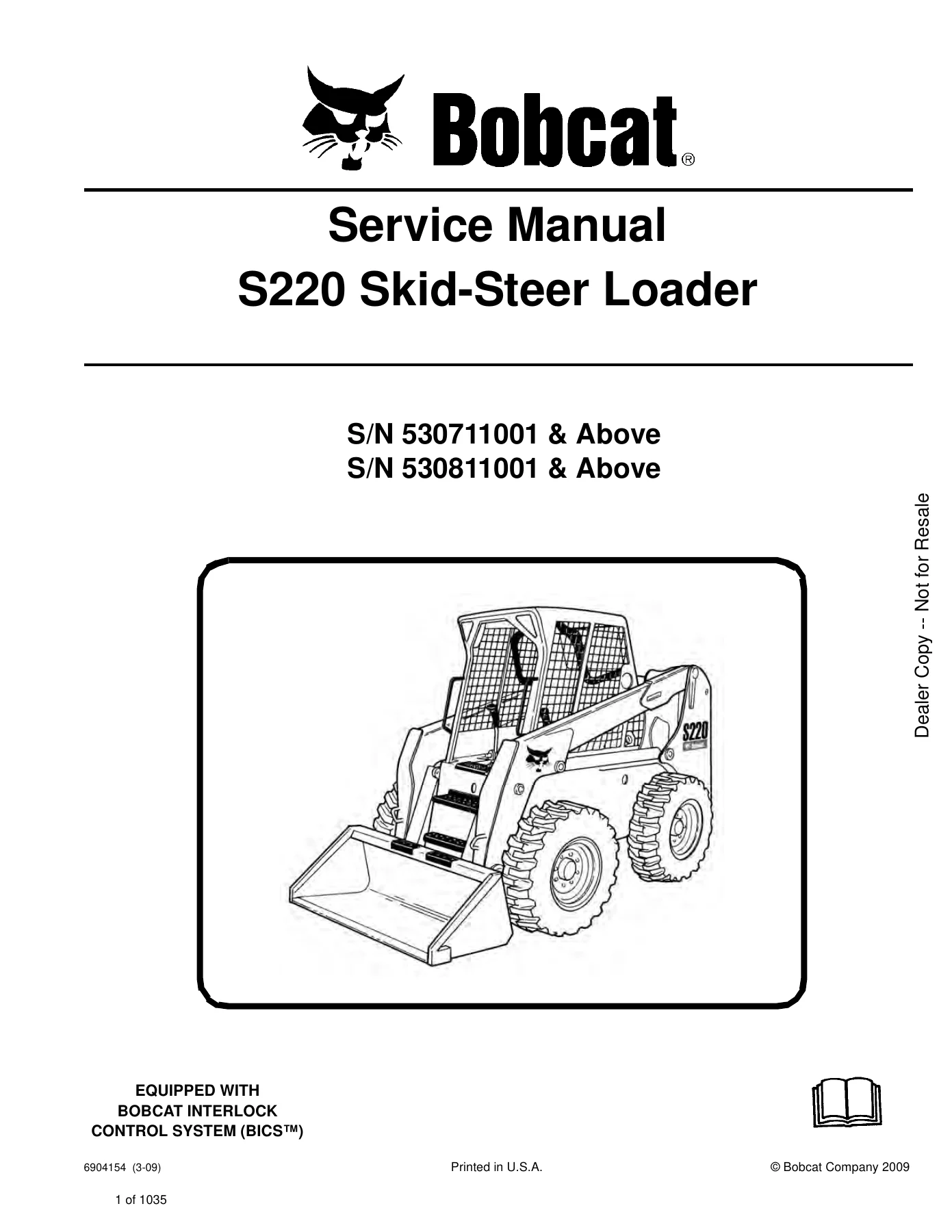
Bobcat S220 Skid-Steer Loader Service Manual - S/N 530711001 & Above, 530811001 & Above β€” PDF page 1 preview
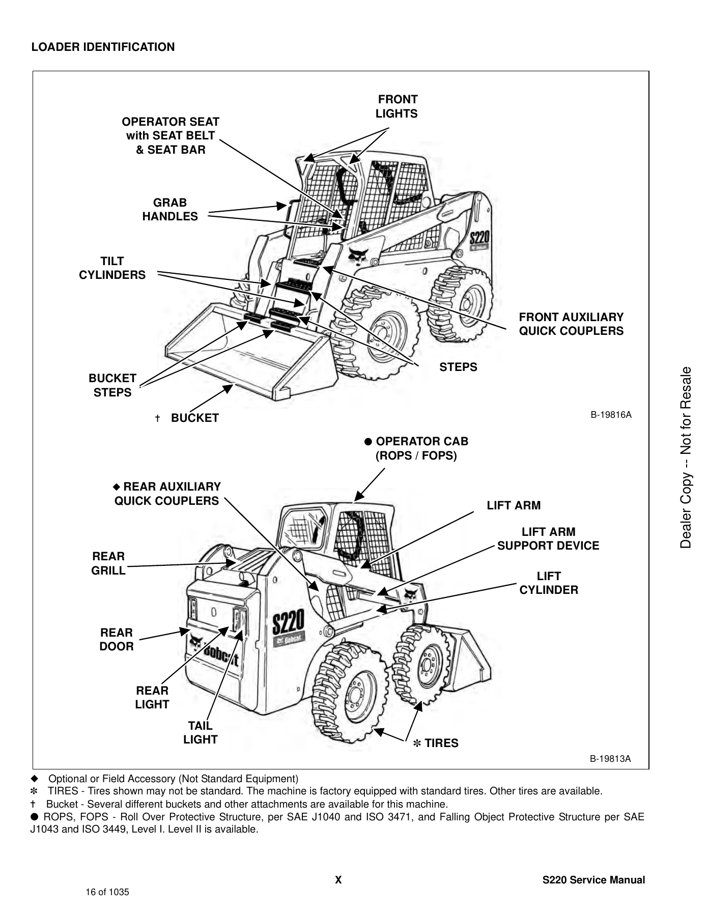
Bobcat S220 Skid-Steer Loader Service Manual - S/N 530711001 & Above, 530811001 & Above β€” PDF page 16 preview
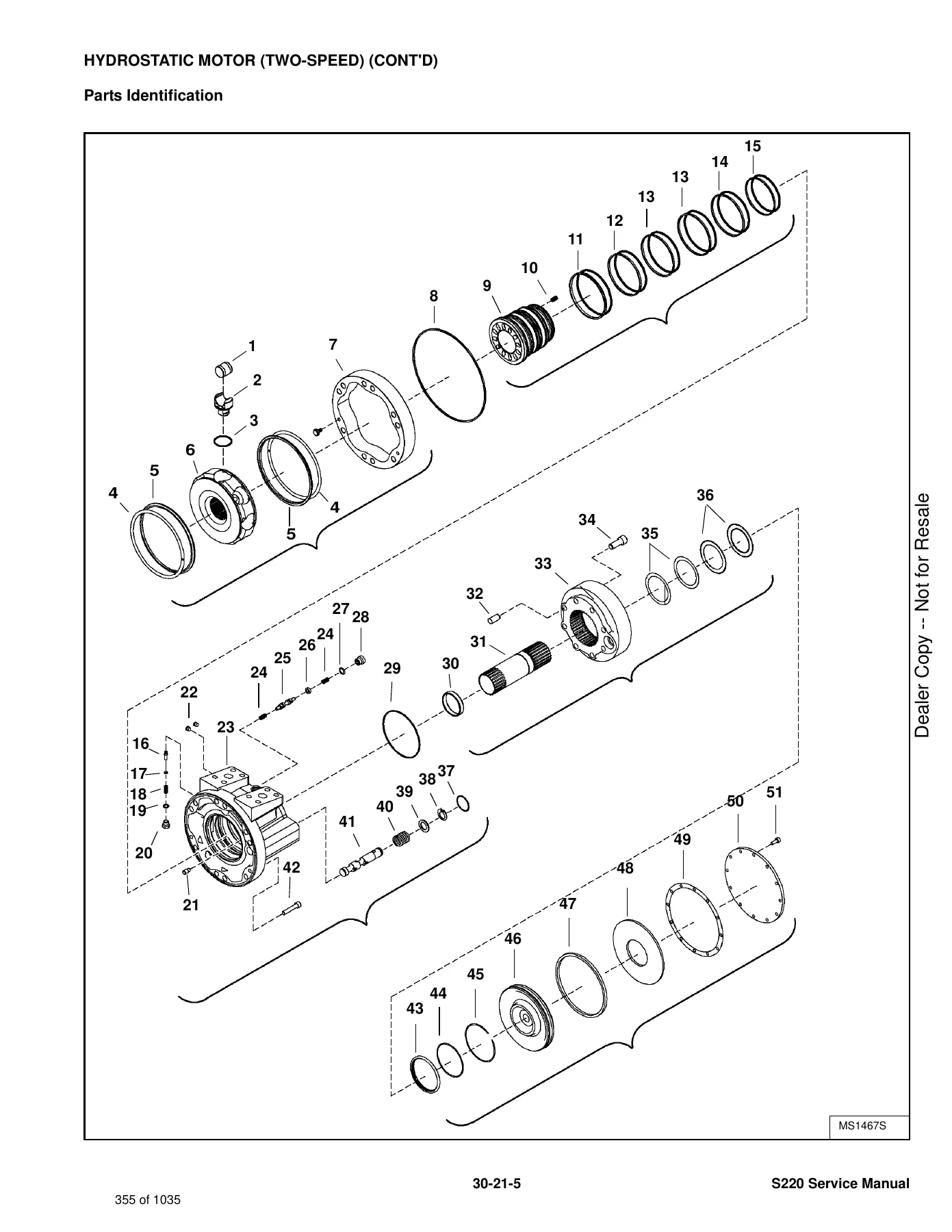
Bobcat S220 Skid-Steer Loader Service Manual - S/N 530711001 & Above, 530811001 & Above β€” PDF page 355 preview

Instant PDF Delivery

The Bobcat S220 Skid-Steer Loader Service Manual is delivered as an instant PDF download after purchase β€” no shipping, no waiting. You can open it on a laptop, tablet, or phone in the shop, print the pages you need for a specific job, and keep the full manual on hand for reference. The PDF format makes it easy to jump to the section you need, whether that is a torque table for a cylinder rebuild, a wiring schematic for a no-start condition, or the service schedule for a scheduled maintenance interval.

Reviews

There are no reviews yet.

Be the first to review “Bobcat S220 Skid-Steer Loader Service Manual – S/N 530711001 & Above, 530811001 & Above”

What Our Customers Say

β˜…β˜…β˜…β˜…β˜… Live reviews from customers
Loading customer reviews...
0
    0
    Your Cart
    Your cart is emptyReturn to Shop
    πŸ›’
    Recently Purchased
    πŸ•’ verified order