
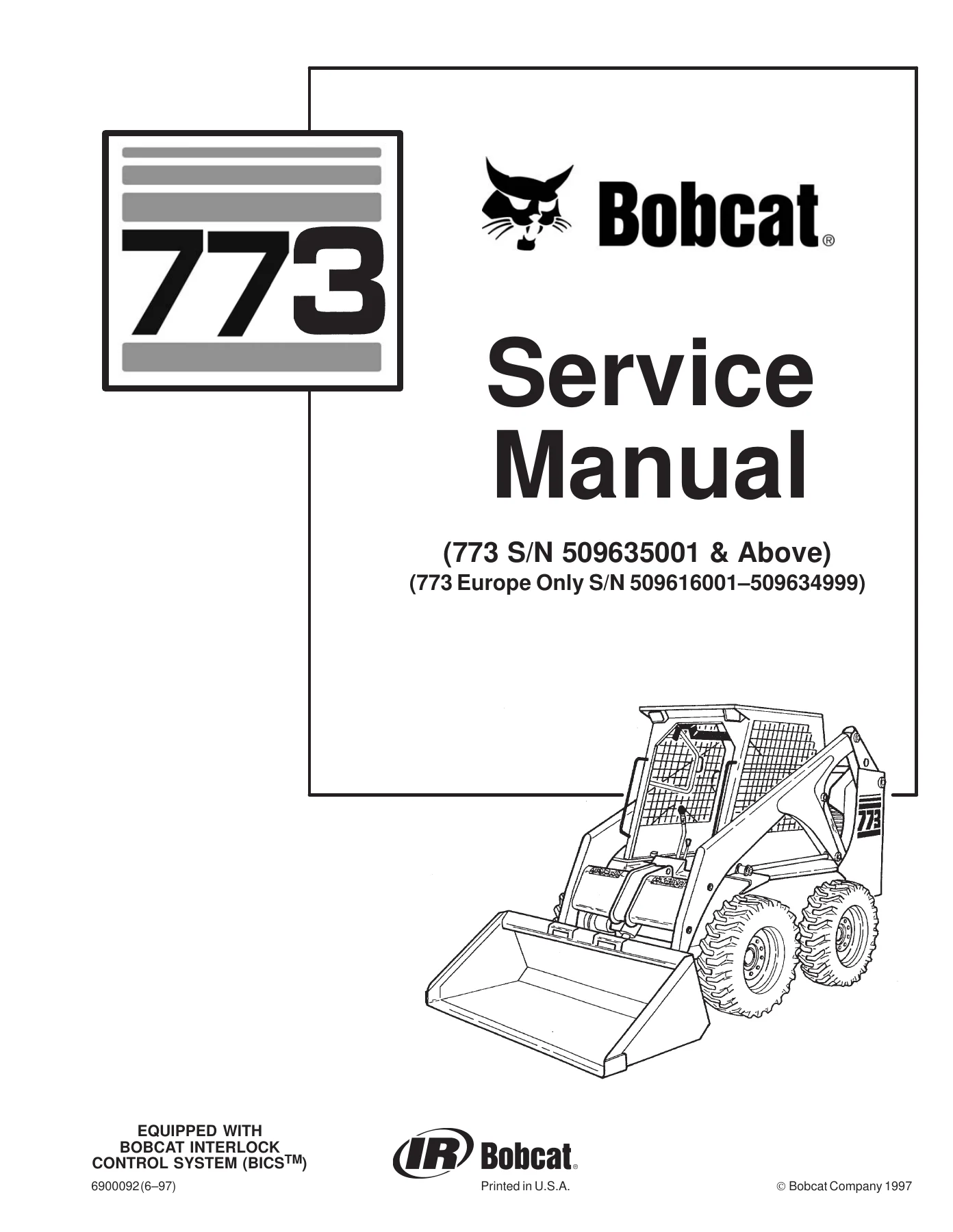
Bobcat 773 Skid Steer Service Manual 6900092 – BICS Loader Repair & Maintenance PDF
Original price was: $59.95.$34.95Current price is: $34.95.
Complete 506-page Bobcat 773 Skid Steer Loader Service Manual (Doc 6900092). Covers BICS system, Kubota V2203EB engine, hydraulics, hydrostatics, drive system, electrical, and Advanced Hand Control. Instant PDF download for professional mechanics and owners.
Description
Bobcat 773 Skid Steer Loader Service Manual – Document 6900092
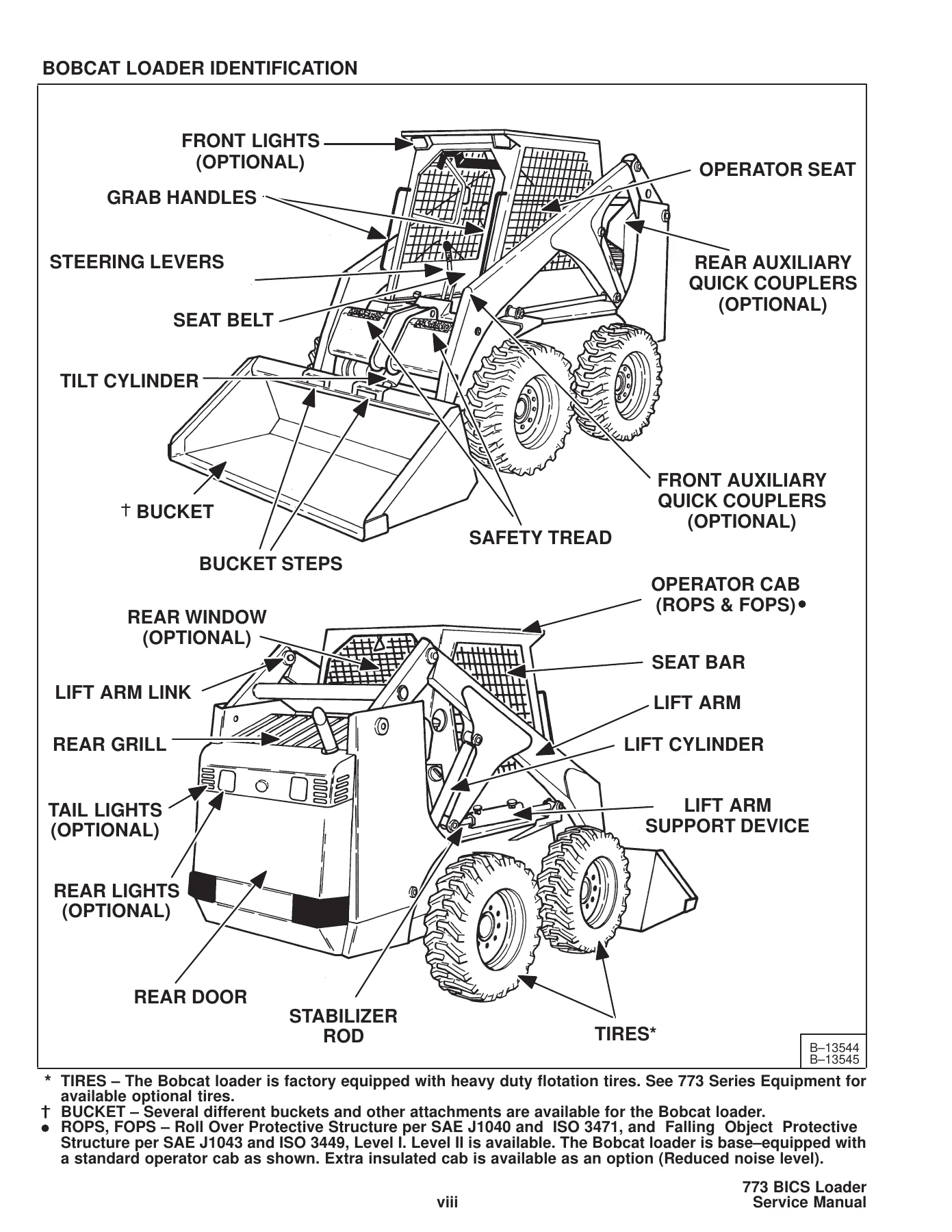
This is the complete Bobcat 773 Service Manual (Document Number 6900092), the same comprehensive repair and maintenance guide used by professional technicians to service, diagnose, and repair the Bobcat 773 skid steer loader. Covering serial numbers 509635001 & Above and Europe-only models 509616001 through 509634999, this 506-page PDF spans every major system on the machine: hydraulic, hydrostatic, drive, main frame, electrical, engine, and the advanced hand control system. Whether you are rebuilding a final drive, troubleshooting a BICS fault code, or adjusting the hydrostatic pump, this manual provides the procedures, specifications, and diagrams needed to get the job done correctly.
File Details
- Manual Type: Service Manual
- Brand: Bobcat
- Model: 773 Skid Steer Loader (including 773 Europe)
- Document Number: 6900092
- Language: English
- Page Count: 506
- File Format: PDF
- Revision Dates: June 2001, November 2001, and earlier revisions included
- Serial Coverage: S/N 509635001 & Above; S/N 509616001 – 509634999 (Europe Only)
Chapters Covered
- Preventive Maintenance
- Hydraulic System
- Hydrostatic System
- Drive System
- Main Frame
- Electrical System
- Engine Service
- Systems Analysis
- Specifications
- Advanced Hand Control System (AHC)
Preventive Maintenance
This section opens with the service schedule chart that maps every maintenance task to its correct interval: 8, 10, 50, 100, 250, 500, and 1000 hours. It walks through checking engine oil, servicing the air cleaner and condition indicator, cleaning the cooling system, checking coolant level, replacing the coolant, inspecting tires and wheel nut torque, servicing the spark arrestor muffler, and maintaining the battery. Detailed procedures cover the hydraulic/hydrostatic fluid check and replacement, hydraulic filter replacement, chaincase oil level check and drain, drive belt adjustment for both fixed and spring-loaded idlers, alternator belt tension, fan gearbox lubricant check, Bob-Tach inspection, pivot pin lubrication, and the seat bar restraint system. The section includes the lift arm support device installation procedure, lifting and blocking the loader, towing, transporting, and the lubrication chart with all grease points.
Hydraulic System
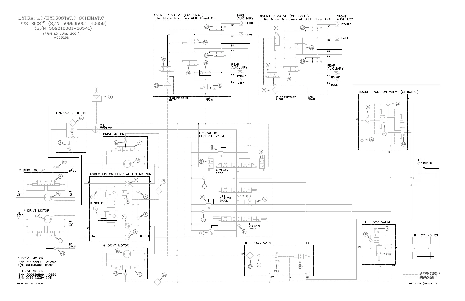
The hydraulic system chapter covers the complete hydraulic circuit from the gear-type hydraulic pump through the main control valve to the lift and tilt cylinders. It includes the hydraulic/hydrostatic schematic with all circuit symbols, the glossary of hydraulic symbols, and detailed procedures for checking and adjusting the main relief valve (3000 PSI at the front quick couplers), servicing the lift and tilt cylinders, checking for internal leakage, and replacing rod end seals. The BICS valve section covers removal, disassembly, assembly, and installation of the lift arm by-pass orifice, check valve, lock valves, and solenoid cartridges for both early and later serial number ranges. The control valve chapter provides the identification chart for all valve sections, load check valve service, port relief valve adjustment, anti-cavitation valve service, spool seal installation, and the complete removal and installation procedure for the main control valve. The hydraulic pump chapter includes output testing, disassembly, assembly, and inspection with torque specifications for all fasteners.
Hydrostatic System
This chapter covers the hydrostatic drive system that powers the loader’s four-wheel drive. It includes the control panel removal and installation, steering lever and steering shaft service, steering linkage adjustment for neutral and full forward travel, and the steering neutral adjustment procedure using the remote start switch. The hydrostatic drive motor section covers both the earlier and later motor designs with complete disassembly and assembly procedures, timing the motor, inspection criteria, and the 30 Series motor service for S/N 509639899 & Above and S/N 509616505 & Above. The hydrostatic pump chapter provides disassembly, assembly, inspection, swashplate pre-load adjustment, and removal and installation procedures for the tandem piston pump with gear pump. The drive belt housing, fixed and spring-loaded drive belt tensioner pulleys, and oil cooler removal and installation are also covered. The hydrostatic system information section explains checking charge pressure and the function of the replenishing valves.
Drive System
The drive system chapter covers the final drive components inside the chaincase: the axle, sprocket, bearings, drive chain, motor carrier, parking brake, and traction lock guides. Procedures include axle seal replacement, axle and sprocket removal and installation, bearing service, drive chain removal and installation with the chain link tool, motor carrier shaft seal replacement, motor carrier disassembly and assembly with bearing and race service, parking brake removal and installation, parking brake disc service, and traction lock guide disassembly and assembly. The chaincase covers are covered for center, front, and rear removal and installation, along with chaincase fluid draining and filling. This section is essential for anyone rebuilding the final drive or repairing a leaking axle seal.
Main Frame
The main frame chapter covers the structural components of the loader: the Bob-Tach attachment mounting system, fuel tank, lift arms, lift arm link, operator cab, operator cab gas cylinder, operator seat, rear door, rear grill, rear lights, and seat bar. Procedures include Bob-Tach lever and wedge service, Bob-Tach stop adjustment, fuel tank removal and installation, fuel level sender service, lift arm removal and installation, lift arm link removal and installation, operator cab removal and installation with gas cylinder service, operator seat removal and installation with seat sensor service, rear door and hood removal and installation for both one-piece and two-piece doors, door latch adjustment, and rear light service. The seat bar section covers both the gas cylinder and compression spring designs with removal, assembly, and gas cylinder compression procedures.
Electrical System
The electrical system chapter covers the 12-volt negative ground alternator charging system with 55-amp alternator, battery service, starter service for both Delco Remy and Denso starters, instrument panel removal and installation, front lights, and relay switches. Procedures include alternator output test, rectifier diode test, alternator regulator test, battery removal and installation, jump starting, starter removal and installation, starter disassembly and assembly, starter inspection and repair, no-load test, and component identification for both starter types. The electrical system information section covers fuse location and the wiring schematic for the 773 with S/N 509635001 and Above and S/N 509616001-34999. The wiring diagram shows the advanced hand control harness, float button harness, and jumper harness connections.
Engine Service
The engine service chapter covers the Kubota V2203EB diesel engine in complete detail: air cleaner, blower housing and fan gearbox, crankshaft and bearings, crankshaft gear, cylinder bore, cylinder head, engine compression, engine muffler, engine speed control, fan gearbox, flywheel, fuel camshaft, fuel injection nozzles, fuel injection pump, glow plugs, idler gear and camshaft, oil pump, piston and connecting rod, radiator, rocker arm and shaft, timing gears, timing gearcase cover, valve clearance, valve seat and guide, water pump, and troubleshooting. Procedures include engine removal and installation, engine mount replacement, compression checking, glow plug checking and replacement, injection pump timing and adjustment, injection nozzle checking and testing, cylinder head removal and disassembly, valve service, piston and connecting rod service, crankshaft and bearing service, oil pump service, and cooling system service. The engine specifications chapter provides all critical dimensions, clearances, and torque values.
Systems Analysis
The systems analysis chapter covers the Bobcat Interlock Control System (BICS) for both early and later serial number ranges, including the BICS controller, seat bar sensor, seat sensor, traction lock, and the troubleshooting charts for each. It covers the BICS inspection procedures for the controller, seat bar sensors, traction lock, and lift arm by-pass control, along with the BICS troubleshooting guide for the controller, seat sensor, seat bar sensor, and traction lock. The chapter also covers the Bobcat Operation Sensing System (BOSS) diagnostic tool, instrument panel, monitor service codes (alphabetic and numeric), operation sensing system unit removal and installation, RPM sensor adjustment, and sender and sensor service checks with ohm values for the temperature sender, engine oil pressure sender, transmission charge pressure sender, fuel sender, and RPM sensor.
Specifications
The specifications chapter provides the complete performance data for the 773 loader: rated operating capacity, tipping load, operating weight, breakout force, axle torque, travel speed, engine specifications, hydraulic system specifications, electrical specifications, drive system specifications, capacities, tire options, and floor pressure. It includes the decimal and millimeter equivalents chart, standard torque specifications for bolts (SAE Grade 5 and Grade 8), hydraulic connection specifications for flare fittings, O-ring face seal connections, O-ring flare fittings, port seal fittings, and straight thread O-ring fittings, along with the U.S. to metric conversion chart and the hydraulic/hydrostatic fluid specifications. This chapter is the go-to reference for any specification or torque value needed during repair or maintenance.
Advanced Hand Control System (AHC)
The Advanced Hand Control System chapter covers the AHC components, AHC/PWM controller, control handle, switch handle, handle control unit, actuators, and the hydraulic control valve specific to AHC-equipped loaders. Procedures include the actuator voltage test, handle control unit test, AHC/PWM controller removal and installation, controller connector and wire identification, handle sensor removal and installation, switch handle removal and installation, control handle removal and disassembly, control lever removal and installation, actuator removal and disassembly, and the hydraulic control valve disassembly and assembly for the lift and tilt spools, auxiliary spool, load check valve, main relief valve, port relief valves, anti-cavitation valve, and spool seal installation. The troubleshooting chart for the AHC system uses the two lights on the left handle to indicate diagnostic codes, and the chapter includes the BICS troubleshooting chart for the interlock system.
Why This Bobcat 773 Service Manual Matters
The Bobcat 773 is a workhorse skid steer loader, and keeping it running correctly requires more than guesswork. This service manual gives you the exact procedures, specifications, and diagrams that Bobcat technicians use in the field. From the hydrostatic pump swashplate pre-load to the BICS controller diagnostic codes, from the engine valve clearance to the chaincase drive chain torque, every critical value and procedure is documented. The hydraulic and hydrostatic schematics alone are worth the investment, showing every circuit, valve, and component in the system so you can trace a problem logically instead of replacing parts blindly. The BICS troubleshooting charts help you diagnose electrical faults quickly by reading the indicator light flash codes. The engine service chapter covers the Kubota V2203EB from top to bottom, including injection pump timing, valve adjustment, and complete disassembly and assembly procedures.
IMAGES PREVIEW
Instant PDF Delivery – No Shipping, No Waiting
This Bobcat 773 Service Manual is delivered as an instant PDF download immediately after payment. There is no shipping, no waiting for a physical book, and no risk of a damaged or lost package. The PDF works on any device: desktop, laptop, tablet, or smartphone. You can print the pages you need for the shop, keep the digital copy on your phone for quick reference, or search the document for specific procedures and specifications. Whether you are a professional heavy equipment mechanic, a farmer maintaining your own equipment, or a weekend warrior tackling a repair project, this manual gives you the information you need to do the job right the first time. Stop guessing and start repairing with the same documentation the professionals use.
Reviews
There are no reviews yet.