★ TRUSTED BY 321,897+ PROFESSIONALS WORLDWIDE
🏢
Trusted Business
Verified & Licensed
🛡️
Virus Free Files
100% Safe Downloads
🔒
Secure Payment
SSL Protected
⚡
Instant Delivery
Available Immediately
Sale!

Bobcat 863 & 863H Skid Steer Loader Service Repair Manual (High Flow) – PDF Download

Original price was: $39.95.Current price is: $24.95.

Complete 506-page Bobcat 863 and 863H Skid Steer Loader Service Repair Manual covering hydraulic, hydrostatic, drive, main frame, electrical, engine service, systems analysis, and full specifications for the covered serial number ranges.

⚡
Instant PDF Download
Available immediately
💾
Save to Your Device
Download & keep forever
🛡️
Antivirus Scanned
100% virus-free
🌍
Trusted Worldwide
175,000+ customers

Description

Bobcat 863 & 863H Skid Steer Loader Service Repair Manual (High Flow)

This Bobcat 863 and 863H Skid Steer Loader Service Repair Manual is the complete workshop reference for the standard 863 and the High Flow 863H. Across 506 pages it documents every major system on these machines — hydraulic, hydrostatic, drive, main frame, electrical and engine — along with full specifications, torque values, service schedules and diagnostic procedures. Whether you are servicing a single machine or running a fleet of these skid steers, this is the reference the shop floor actually needs.

File Details

  • Manual Type: Complete Service Repair Manual
  • Brand: Bobcat
  • Models Covered: 863, 863H (High Flow)
  • Serial Number Ranges: 514411001–514424999, 514511001–514524999, 514611001–514624999
  • Language: English
  • Page Count: 506 pages
  • File Format: PDF
  • Document Number: 6724799 (4-96)
  • Publication Date: April 1996, updated by revisions through July 2010
  • Printed in: U.S.A.

Chapters Covered

The Bobcat 863 and 863H service manual is organised into nine numbered sections, each one a full subsystem reference on its own:

  • Section 1 – Safety and Maintenance: Service Schedule, Lifting and Blocking the Loader, Lift Arm Support Device, Operator Cab (raising/lowering, emergency exit), Seat Bar Restraint System, Air Cleaner Service, Fuel System (specs, filter, bleeding), Engine Lubrication (oil and filter), Cooling System, Alternator Belt, Hydraulic/Hydrostatic Fluid and Filters, Wheel Nuts and Tire Rotation, Final Drive Transmission (Chaincase), Lubricating the Loader, Fan Gearbox, Remote Start Switch
  • Section 2 – Hydraulic System: Hydraulic Cylinders (lift and tilt — disassembly, assembly, seals), BICS Control Valve (lock valve, check valve, solenoid, lift arm by-pass orifice), Hydraulic Control Valve (load check, main relief, port relief, anti-cavitation, spools, seals, rubber boot), Main Relief Valve (checking, adjusting, removal), Select Valve 863H (high flow relief, disassembly, solenoid testing), Lift Arm By-Pass Control Valve, Hydraulic Pump (output check, disassembly, inspection, assembly), Double Gear Pump 863H, Hydraulic Filter Housings, Hydraulic Fluid Reservoir, Control Pedals and Pedal Interlock Linkage, Rear Auxiliary Diverter
  • Section 3 – Hydrostatic System: Front Panel (solid and cable steering linkage), Steering Levers, Control Tower, Hydrostatic Motor (removal, disassembly, inspection, assembly), Hydrostatic Pump (removal, separation, charge pump, disassembly, inspection, assembly), Steering Neutral Adjustment (solid linkage and cable), Wheel RPM Forward vs Reverse, Left vs Right Adjustment, Swashplate Neutral Adjustment, Displacement Control Servo, Drive Belt and Tensioner Pulley, Drive Belt Shield, Oil Cooler
  • Section 4 – Drive System: Parking Brake Pedal and Disc, Front and Rear Chaincase Covers, Axle Seal, Axle/Sprocket/Bearings, Motor Carrier (removal, disassembly, assembly, shaft seal), Drive Chain, Chaincase Fluid Drain
  • Section 5 – Main Frame: Seat Bar (gas spring and compression spring versions), Operator Cab, Operator Cab Gas Cylinder, Operator Seat, Bob-Tach (lever, wedge, stops, pivot pin bushing and seals), Lift Arms, Rear Grill, Rear Door (one-piece and two-piece), Fuel Tank and Level Sender
  • Section 6 – Electrical System: Alternator (output test, regulator test, rectifier/diode test, disassembly, assembly), Battery (removal, servicing, booster battery use), Starter (disassembly, external pinion, inspection and repair, magnetic switch test, no-load test), Standard Instrument Panel, Front Lights, Relay Switches
  • Section 7 – Engine Service: Engine Speed Control, Engine Muffler, Air Cleaner Housing, Blower Housing / Fan Gearbox, Blower Fan, Fan Drive Tension Pulley, Flywheel and Ring Gear, Glow Plugs, Valve Clearance Adjustment, Fuel Injection Pump (removal, timing, installation), Fuel Injector (check, disassembly, assembly), Timing Belt (inspection, removal, installation, belt replacement in loader), Valve Timing, Reconditioning the Engine (full disassembly and assembly), Cylinder Liners, Camshaft Bearings, Control Rod Guide Bushing, Rear Cover Seal, Crankshaft, Connecting Rod, Pistons and Piston Pin, Cylinder Head, Rocker Arm and Bracket, Front Cover, Turbocharger, Positive Crankcase Ventilation System, Oil Cooler, Crankshaft Gear Mounting Bolt Torque Procedure
  • Section 8 – Systems Analysis: Bobcat Interlock Control System (BICS) — inspection, maintenance, troubleshooting chart, troubleshooting guide; BICS System Controller (removal, controller test); Seat Bar Sensor and Seat Sensor (removal, test); Traction Lock; BOSS Diagnostic Tool; Service Codes (alphabetical and numeric); BOSS Instrument Panel; Operation Sensing System Unit; PWM Module (description, voltage table, troubleshooting chart); PWM Control Handle and PWM Electric Solenoid; Electrical/Hydraulic Controls Reference Chart
  • Section 9 – Specifications: Loader Specifications (performance, controls, engine, dimensions, capacities, tires), Engine Specifications for the BF4M1011 and BF4M1011F (general, fuel system, valves, pistons and rings, connecting rod, crankshaft and main bearings, camshaft, oil pump), Engine Torque Specifications, Torque Specifications for Loader, Hydraulic Connection Specifications (flare, O-ring flare, O-ring face seal, port seal, straight thread O-ring, tubelines and hoses), Hydraulic/Hydrostatic Fluid Specifications, Standard Torque Specifications for Bolts, Decimal and Millimeter Equivalents, U.S. to Metric Conversion Chart

What This Manual Enables You To Do

This Bobcat 863 863H skid steer loader service repair manual goes far beyond routine maintenance. The hydraulic and hydrostatic sections cover every pump, motor, cylinder, control valve and relief valve in the circuit, with step-by-step removal, disassembly, inspection and reassembly procedures plus the correct torque values for each fastener. The engine section covers the full Deutz BF4M1011 and BF4M1011F service envelope — valve clearance, injector testing, injection pump timing and installation, timing belt replacement, cylinder head work, crankshaft and bearing measurement, turbocharger rebuild and full engine reconditioning. The drive section handles the chaincase, axles, sprockets, bearings, motor carrier and parking brake, and the electrical section includes alternator, starter and battery diagnostics with output, regulator and no-load tests. Systems Analysis gives you the BICS and BOSS diagnostic material: fault code charts, sensor tests and controller diagnostics so electrical and interlock faults can be isolated quickly rather than guessed at.

Covered Serial Numbers

This manual applies to three serial number ranges: S/N 514411001–514424999, S/N 514511001–514524999, and S/N 514611001–514624999. Always confirm your machine’s serial number against these ranges before ordering parts or following a procedure, since early and later machines within a model line can use different components or require a different procedure for the same operation.

Who This Bobcat 863 & 863H Service Manual Is For

This is a workshop-grade service manual written for the mechanic who is actually working on the machine. Independent shops, fleet maintenance departments, farm and construction owners who run their own repairs, and anyone maintaining a Bobcat 863 or 863H skid steer will find the procedures, clearances, torque figures and diagnostic charts they need in one place. The manual assumes the reader has basic mechanical ability and access to common hand tools and measuring equipment; specialised tools are called out by their Bobcat tool numbers where a procedure requires them, so you know in advance when a job needs a specific puller, driver, seal installer or testing kit.

Hydraulic, Hydrostatic and Engine Coverage in Depth

The hydraulic system section covers the complete circuit on both models, including the High Flow select valve unique to the 863H. You get the main relief valve check and adjustment, port relief and anti-cavitation valve service, load check valves, all three spools (lift, tilt and auxiliary) with their detents and centering springs, the BICS control valve with its lock valves and lift arm by-pass orifice, and the lift arm by-pass control valve. The hydraulic pump and the double gear pump used on the High Flow model both have output testing, disassembly, inspection and assembly procedures, along with the case drain filters and the hydraulic fluid reservoir. On the hydrostatic side, the tandem piston pump and the hydrostatic motor are treated as full rebuild candidates, and the manual walks through swashplate neutral adjustment, steering neutral setting, and the forward vs reverse / left vs right wheel RPM balance procedure that keeps these loaders tracking straight. On the engine side, the manual covers the Deutz BF4M1011 and BF4M1011F completely: fuel injection pump timing and installation depth (with shim selection), injector opening pressure and spray pattern checks, timing belt alignment and tension, valve clearance, cylinder head and valve seat inspection, piston and ring measurement, crankshaft and main bearing clearances, camshaft and bearing service, and turbocharger disassembly, inspection and assembly with axial and radial play limits.

Systems Analysis and Diagnostics

The Systems Analysis section is what separates this manual from a basic repair guide. It documents the Bobcat Interlock Control System (BICS) with a full troubleshooting chart and troubleshooting guide for the seat sensor, seat bar sensor, valve output and traction lock circuits; the BICS controller test procedure; the BOSS diagnostic tool procedure; the BOSS and LCD display troubleshooting chart; the full service code list (both numeric and alphabetic) with what each code means; the PWM module voltage table and PWM troubleshooting chart with blinking-light diagnostic codes for the base end, rod end and diverter solenoids; the PWM control handle switch test values; and the operation sensing system unit. If you have ever chased an intermittent BICS light or a random traction lock fault on one of these loaders, this is the material that lets you test the right circuit in the right order instead of replacing parts on suspicion.

Complete PDF Bookmark Tree

Complete Bookmarks

The complete bookmarks in the “Bobcat 863 & 863H Skid Steer Loader Service Repair Manual (High Flow) – PDF Download” are as follows:

MAINTENANCE SAFETp. 3
CONTENTSp. 5
FOREWORDp. 6
SAFETY INSTRUCTIONSp. 9
SERIAL NUMBER LOCATIONSp. 11
LOADER SERIAL NUMBERp. 11
DELIVERY REPORTp. 11
BOBCAT LOADER IDENTIFICATIONp. 12
OPTIONS AND ACCESSORIESp. 13
PREVENTIVE MAINTENANCEp. 15
SERVICE SCHEDULEp. 17
LIFTING AND BLOCKING THE LOADERp. 18
Procedurep. 18
TRANSPORTING THE BOBCAT LOADERp. 19
Procedurep. 19
TOWING THE LOADERp. 19
LIFT ARM SUPPORT DEVICEp. 20
To Install The Lift Arm Support Devicep. 20
To Remove The Lift Arm Support Devicep. 21
OPERATOR CABp. 22
Descriptionp. 22
Raising The Operator Cabp. 22
Lowering The Operator Cabp. 23
Emergency Exitp. 23
SEAT BAR RESTRAINT SYSTEMp. 24
Descriptionp. 24
Seat Bar Inspectionp. 24
Seat Bar Maintenancep. 24
AIR CLEANER SERVICEp. 25
Replacing Filter Elementp. 25
FUEL SYSTEMp. 27
Fuel Specificationsp. 27
Filling The Fuel Tankp. 27
Fuel Filterp. 27
Removing Air From The Fuel Systemp. 27
ENGINE LUBRICATION SYSTEMp. 28
Checking Engine Oilp. 28
Replacement Of Oil And Filterp. 28
COOLING SYSTEMp. 29
Cleaning The Cooling Systemp. 29
ALTERNATOR BELTp. 30
Adjusting The Alternator Beltp. 30
HYDRAULIC/HYDROSTATIC SYSTEMp. 31
Checking And Adding Fluidp. 31
Replacing The Hydraulic/Hydrostatic Filterp. 31
Replacing The Hydraulic Fluidp. 32
TIRE MAINTENANCEp. 33
Wheel Nutsp. 33
Tire Rotationp. 33
Tire Mountingp. 33
FINAL DRIVE TRANSMISSION (CHAINCASE)p. 34
Checking And Adding Oilp. 34
Removing Oil From The Chaincasep. 34
LUBRICATION OF THE BOBCAT LOADERp. 35
Procedurep. 35
FAN GEARBOXp. 36
Checking And Maintainingp. 36
REMOTE START SWITCHp. 37
Procedurep. 37
HYDRAULIC SYSTEMp. 39
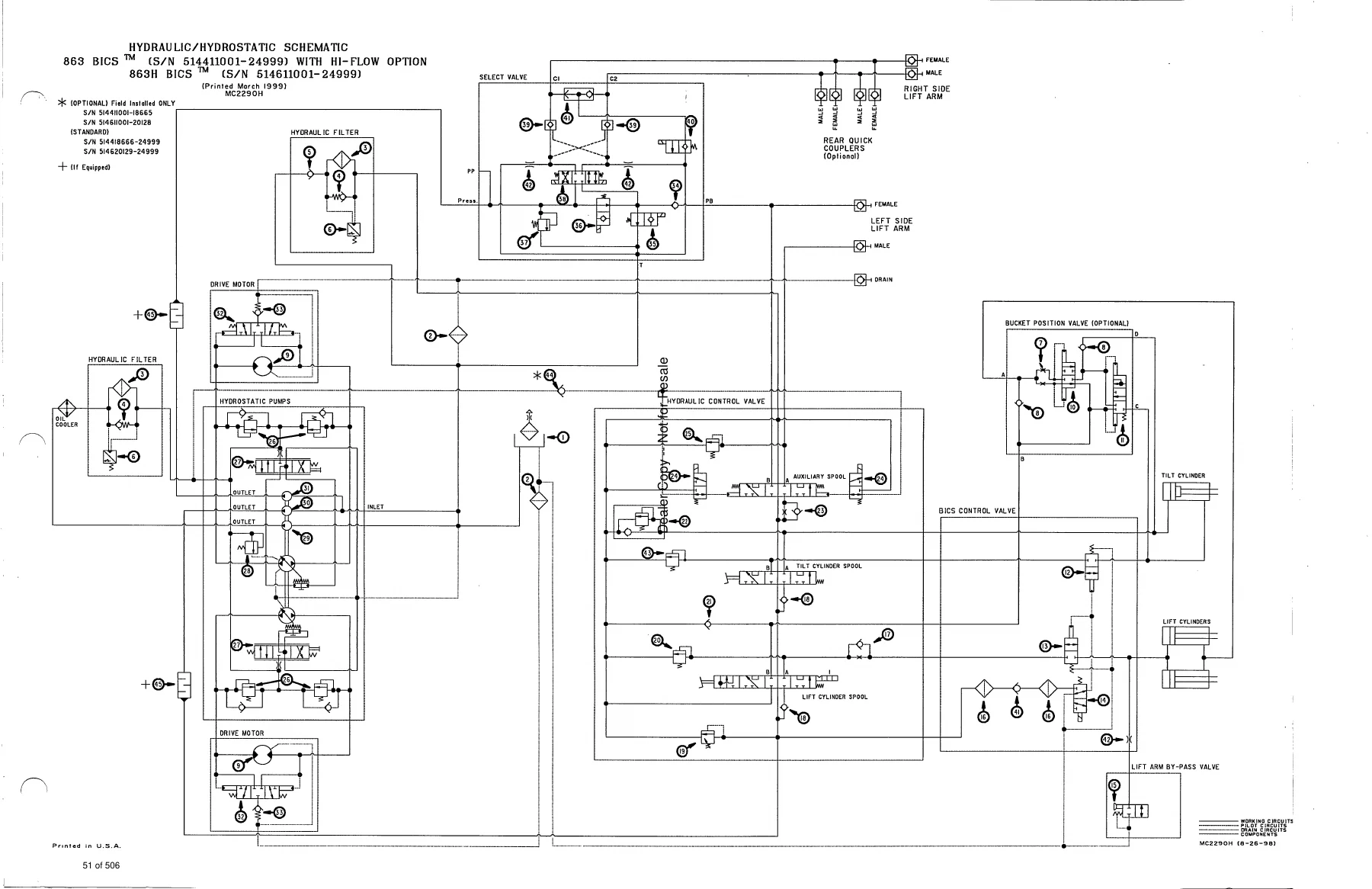
HYDRAULIC / HYDROSTATIC SCHEMATICSp. 41
TROUBLESHOOTINGp. 53
HYDRAULIC SYSTEM INFORMATIONp. 54
Tighten Proceduresp. 54
LIFT CYLINDER(S)p. 55
Checking The Lift Cylinder(s)p. 55
Removal And Installationp. 55
TILT CYLINDERp. 57
Checking The Tilt Cylinderp. 57
Removal And Installationp. 57
Rod End Sealp. 58
HYDRAULIC CYLINDERp. 59
Lift Cylinder Identificationp. 59
Tilt Cylinder Identificationp. 60
Disassemblyp. 61
Assemblyp. 63
MAIN RELIEF VALVEp. 66
Checking The Main Relief Valvep. 66
Checking The Main Relief Valve Without Auxiliariesp. 67
Removal And Installationp. 68
Adjustmentp. 68
SELECT VALVE 863Hp. 69
Checking The High Flow Pump Relief Valvep. 69
Removal And Installationp. 70
Disassembly And Assemblyp. 71
Solenoid Testingp. 72
LIFT ARM BY–PASS CONTROL VALVEp. 73
Removal And Installationp. 73
Disassembly And Assemblyp. 74
BICS™ CONTROL VALVEp. 75
Removal And Installationp. 75
BICS™ VALVE ASSEMBLYp. 78
Lift Arm By–Pass Orificep. 78
Check Valvep. 79
Lock Valvep. 80
BICS™ Valve Solenoidp. 81
HYDRAULIC CONTROL VALVEp. 82
Removal And Installationp. 82
Identification Chartp. 86
Disassembly And Assemblyp. 87
Load Check Valvep. 87
Lift Base End Restrictorp. 87
Main Relief Valvep. 88
Port Relief Valvep. 89
Anti–Cavitation/Port Relief Valvep. 89
Rubber Bootp. 91
Lift Spool And Detentp. 92
Tilt Spool And Centering Springp. 96
Auxiliary Spoolp. 97
Auxiliary Electric Solenoidp. 98
H Port – Auxiliary Sectionp. 99
Inspectionp. 99
Spool Seal Installationp. 100
HYDRAULIC PUMPp. 101
Checking The Output Of The Pumpp. 101
Removal And Installationp. 102
Parts Identificationp. 103
Disassemblyp. 104
Inspectionp. 106
Assemblyp. 107
HYDRAULIC PUMP (Double Gear) 863Hp. 109
Checking The Output Of The High Flow Pumpp. 109
Removal And Installationp. 110
Parts Identificationp. 112
Disassemblyp. 113
Inspectionp. 117
Assemblyp. 118
HYDRAULIC FLUID RESERVOIRp. 121
Removal And Installationp. 121
HYDROSTATIC FILTER HOUSINGp. 122
Removal And Installationp. 122
Hydrostatic Charge Pressure Senderp. 122
HYDRAULIC FILTER HOUSINGp. 123
Removal And Installationp. 123
CONTROL PEDALSp. 124
Removal And Installationp. 124
Pedal Adjustmentp. 124
PEDAL INTERLOCK LINKAGEp. 125
Removal And Installationp. 125
Pedal Interlock Linkage Adjustmentp. 126
REAR AUXILIARY DIVERTERp. 127
Disassemblyp. 127
Inspectionp. 127
Solenoid Testingp. 127
Assemblyp. 127
HYDROSTATIC SYSTEMp. 129
TROUBLESHOOTINGp. 131
HYDROSTATIC SYSTEM INFORMATIONp. 132
Replenishing Valve Functionp. 132
FRONT PANEL (SOLID STEERING LINKAGE)p. 133
Removal And Installationp. 133
FRONT PANEL (CABLE STEERING LINKAGE)p. 135
Removal And Installationp. 135
STEERING LEVERSp. 137
Disassembly And Assemblyp. 137
CONTROL TOWER (SOLID STEERING LINKAGE)p. 139
Removal And Installationp. 139
Disassembly And Assemblyp. 140
SOLID STEERING LINKAGE NEUTRAL ADJUSTMENTp. 142
Procedurep. 142
CABLE STEERING LINKAGE NEUTRAL ADJUSTMENTp. 145
Pre–Adjustment Checksp. 145
Adjusting Lever Freeplayp. 146
Adjusting The Wheel RPM Forward Compared to Reverse Travelp. 147
Adjusting The Steering Neutral Settingp. 149
Adjusting The Wheel RPM Left Compared To Right Sidep. 150
HYDROSTATIC MOTORp. 151
Removal And Installationp. 151
Parts Identificationp. 153
Disassemblyp. 154
Inspectionp. 157
Assemblyp. 158
HYDROSTATIC PUMPp. 162
Removal And Installationp. 162
Replenishing/High Pressure Relief Valvep. 164
Parts Identificationp. 166
Hydraulic Pump Removalp. 170
Hydrostatic Pump Separationp. 170
Charge Pump Disassemblyp. 171
Disassemblyp. 172
Inspectionp. 181
Assemblyp. 183
Charge Pump Assemblyp. 192
Hydrostatic Pump Connectionp. 193
Hydraulic Pump Installationp. 194
Swashplate Neutral Adjustmentp. 195
Displacement Control Servo (Solid Linkage)p. 196
Displacement Control Servo (Cable Linkage)p. 197
DRIVE BELT SHIELDp. 199
Removal And Installationp. 199
DRIVE BELTp. 200
Adjusting The Drive Beltp. 200
Replacing The Drive Beltp. 200
DRIVE BELT TENSIONER PULLEYp. 201
Removal And Installationp. 201
Tension Springp. 203
OIL COOLERp. 204
Removal And Installationp. 204
DRIVE SYSTEMp. 205
PARKING BRAKE PEDALp. 207
Removal And Installationp. 207
Disassembly And Assemblyp. 208
PARKING BRAKE DISCp. 209
Removal And Installationp. 209
FRONT CHAINCASE COVERp. 212
Removal And Installationp. 212
REAR CHAINCASE COVERp. 212
Removal And Installationp. 212
AXLE SEALp. 213
Removal And Installationp. 213
AXLE, SPROCKET AND BEARINGSp. 215
Removal And Installationp. 215
MOTOR CARRIERp. 219
Shaft Seal Replacementp. 219
Removal And Installationp. 220
Parts Identificationp. 222
Disassemblyp. 223
Assemblyp. 225
DRIVE CHAINp. 229
Removal And Installationp. 229
CHAINCASE FLUIDp. 230
Removing The Fluid From The Chaincasep. 230
MAIN FRAMEp. 231
SEAT BAR (W/GAS SPRING)p. 233
Removal And Installationp. 233
Seat Bar Pivot Assemblyp. 235
Compressing The Gas Cylinderp. 236
Assemblyp. 237
SEAT BAR (W/COMPRESSION SPRING)p. 238
Removal And Installationp. 238
Assembling Componentsp. 241
Compression Spring Disassembly And Assemblyp. 241
OPERATOR CAB GAS CYLINDERp. 242
Removal And Installationp. 242
Disassembly And Assemblyp. 243
OPERATOR CABp. 244
Removal And Installationp. 244
OPERATOR SEATp. 246
Removal And Installationp. 246
BOB–TACHp. 247
Bob–Tach Lever And Wedgep. 247
Bob–Tach Stopsp. 248
Removal And Installationp. 249
Pivot Pin Bushing And Seal Replacementp. 251
LIFT ARMSp. 252
Removal And Installationp. 252
REAR GRILLp. 255
Removal And Installationp. 255
REAR DOOR (ONE PIECE)p. 256
Removal And Installationp. 256
Door Latch And Catch Adjustmentp. 257
REAR DOORp. 258
Removal And Installationp. 258
Hood Removal And Installationp. 259
Bumper Removal And Installationp. 259
Door Latch Removal And Installationp. 259
Door Latch And Catch Adjustmentp. 259
FUEL TANKp. 260
Removal And Installationp. 260
Fuel Level Senderp. 261
Fuel Pick–Up Screen/Check Valvep. 261
Inlet Screenp. 262
ELECTRICAL SYSTEMp. 263
ELECTRICAL SCHEMATICSp. 265
TROUBLESHOOTINGp. 289
ELECTRICAL SYSTEM INFORMATIONp. 290
Descriptionp. 290
Fuse Locationp. 290
BATTERYp. 291
Removal And Installationp. 291
Servicing The Batteryp. 292
Using A Booster Batteryp. 293
ALTERNATORp. 294
Alternator Output Testp. 294
Rectifier (Diode) Testp. 294
Alternator Regulator Testp. 295
Removal And Installationp. 296
Disassemblyp. 297
Stator Continuity Testp. 297
Stator Ground Testp. 297
Rotor Continuity Testp. 298
Rotor Ground Testp. 298
Rectifier Continuity (Diode) Testp. 298
Assemblyp. 299
STARTERp. 299
Removal And Installationp. 299
Parts Identificationp. 300
Disassembly And Assemblyp. 301
External Pinionp. 305
Inspection And Repairp. 306
Magnetic Switch Testp. 309
No Load Testp. 309
STANDARD INSTRUMENT PANELp. 310
Removal And Installationp. 310
FRONT LIGHTSp. 311
Removal And Installationp. 311
RELAY SWITCHESp. 312
Locationp. 312
ENGINE SERVICEp. 313
TROUBLESHOOTINGp. 315
ENGINE SPEED CONTROLp. 316
Removal And Installationp. 316
Speed Control Cablep. 317
Speed Control Linkagep. 317
ENGINE MUFFLERp. 318
Removal And Installationp. 318
AIR CLEANER HOUSINGp. 319
Removal And Installationp. 319
BLOWER HOUSING/FAN GEARBOXp. 320
Removal And Installationp. 320
FAN DRIVE TENSION PULLEYp. 322
Removal And Installationp. 322
BLOWER FANp. 323
Removal And Installationp. 323
FAN GEARBOXp. 324
Parts Identificationp. 324
Disassemblyp. 325
Assemblyp. 330
Checking Backlashp. 335
ENGINEp. 338
Removal And Installationp. 338
ENGINE MOUNTSp. 344
Replacementp. 344
FLYWHEELp. 345
Removal And Installationp. 345
Flywheel Ring Gearp. 345
FLYWHEEL HOUSINGp. 345
Removal And Installationp. 345
GLOW PLUGp. 346
Checking The Glow Plugp. 346
VALVE CLEARANCEp. 347
Adjustmentp. 347
FUEL INJECTION PUMPp. 348
Descriptionp. 348
Removalp. 348
Installationp. 350
FUEL INJECTORp. 352
Removal And Installationp. 352
Checkingp. 353
Disassemblyp. 354
Assemblyp. 355
TIMING BELTp. 357
Inspectionp. 357
Removalp. 357
Installationp. 358
Belt Replacement In Loaderp. 361
VALVE TIMINGp. 366
Checkingp. 366
DEUTZ ENGINE TOOLSp. 367
Identification Chartp. 367
RECONDITIONING THE ENGINEp. 368
Disassemblyp. 368
Assemblyp. 372
CYLINDER LINERSp. 387
Checking The Cylinder Linersp. 387
CAMSHAFT BEARINGSp. 388
Checkingp. 388
Removal And Installationp. 388
CONTROL ROD GUIDE BUSHINGp. 390
Removalp. 390
Installationp. 392
REAR COVER SEALp. 396
Removal And Installationp. 396
CRANKSHAFTp. 397
Checking The Crankshaftp. 397
CONNECTING RODp. 398
Checking The Connecting Rodp. 398
PISTON AND PISTON PINp. 401
Checking The Pistonp. 401
Checking Piston Pinp. 402
Installing Piston Ringsp. 402
CYLINDER HEADp. 403
Disassemblyp. 403
Checking The Valvesp. 403
Checking Valve Seatsp. 404
Valve Springp. 404
Assemblyp. 404
ROCKER ARM AND BRACKETp. 406
Checkingp. 406
FRONT COVERp. 407
Disassemblyp. 407
Assemblyp. 412
TURBOCHARGERp. 422
Removal And Installationp. 422
Disassemblyp. 423
Inspectionp. 427
Assemblyp. 428
POSITIVE CRANKCASE VENTILATION SYSTEM(S/N 514415609, 514611152, 514511106 & Below)p. 433
Descriptionp. 433
Inspectionp. 433
Module Removal And Installationp. 434
OIL COOLERp. 435
Removal And Installationp. 435
CRANKSHAFT GEAR MOUNTING BOLTp. 436
Torque Procedurep. 436
SYSTEMS ANALYSISp. 437
BOBCAT INTERLOCK CONTROL SYSTEM (BICS™)p. 439
Inspecting The BICS™ Controller (Engine STOPPED – Key ON)p. 439
Inspecting Deactivation Of The Auxiliary HydraulicsSystem (Engine STOPPED – Key ON)p. 439
Inspecting The Seat And Seat Bar Sensors (Engine RUNNING)p. 439
Inspecting The Traction Lock (Engine RUNNING)p. 439
Inspecting The Lift Arm By–Pass Controlp. 439
Maintenancep. 439
Troubleshooting Chartp. 440
SEAT SENSOR OVERRIDE ONLY (If Equipped)p. 440
Troubleshooting Guidep. 441
BICS SYSTEM CONTROLLERp. 441
TRACTION LOCKp. 442
SEAT SENSORp. 443
SEAT BAR SENSORp. 444
LIFT ARM BY–PASS VALVEp. 445
BICS™ SYSTEM CONTROLLERp. 446
Removal And Installationp. 446
Controller Testp. 447
SEAT BAR SENSORp. 448
Removal And Installationp. 448
Seat Bar Sensor Testp. 449
SEAT SENSORp. 450
Removal And Installationp. 450
Seat Sensor Testp. 451
TRACTION LOCKp. 452
Removal And Installationp. 452
BOSS® DIAGNOSTIC TOOLp. 453
Procedurep. 453
SENDER AND SENSORp. 453
Service Checksp. 453
Componentsp. 453
RPM SENSORp. 453
Adjustmentp. 453
MONITOR SERVICE CODESp. 454
TROUBLESHOOTING THE BOSS® & LCD DISPLAYp. 457
OPERATION SENSING SYSTEM UNITp. 458
Removal And Installationp. 458
BOSS® INSTRUMENT PANELp. 459
Removal And Installationp. 459
PWM MODULEp. 460
Descriptionp. 460
Troubleshooting Chartp. 462
PWM CONTROL HANDLEp. 463
Handle Testingp. 463
PWM ELECTRIC SOLENOIDp. 463
Solenoid Coil Testingp. 463
ELECTRICAL/HYDRAULIC CONTROLS REFERENCEp. 464
Controls Identification Chartp. 464
SPECIFICATIONSp. 465
LOADER SPECIFICATIONSp. 467
LOADER DIMENSIONSp. 467
PERFORMANCEp. 467
CONTROLSp. 467
ENGINEp. 467
HYDRAULIC SYSTEMp. 468
ELECTRICALp. 468
DRIVE SYSTEMp. 468
CAPACITIESp. 469
TIRESp. 469
ENGINE SPECIFICATIONS (BF4M1011)p. 470
Generalp. 470
Fuel Systemp. 470
Valve And Valve Guide And Seat Insertp. 470
Piston And Ringsp. 471
Connecting Rodp. 471
Cylinder Head And Blockp. 471
Crankshaft And Main Bearingsp. 472
Camshaft And Bearingsp. 472
Oil Pumpp. 472
ENGINE SPECIFICATIONS (BF4M1011F)p. 473
Generalp. 473
Fuel Systemp. 473
Valve And Valve Guide And Seat Insertp. 473
Piston And Ringsp. 474
Connecting Rodp. 474
Crankshaft And Main Bearingsp. 475
Camshaft And Bearingsp. 475
Oil Pumpp. 475
ENGINE TORQUEp. 476
Specificationsp. 476
Torque For General Metric Boltsp. 477
TORQUE SPECIFICATIONS FOR LOADERp. 478
HYDRAULIC CONNECTION SPECIFICATIONSp. 479
O–ring Face Seal Connectionp. 479
Straight Thread O–ring Fittingp. 479
Tubelines And Hosesp. 479
Flare Fittingp. 479
O–ring Flare Fittingp. 480
Port Seal Fittingp. 482
HYDRAULIC/HYDROSTATIC FLUID SPECIFICATIONSp. 483
STANDARD TORQUE SPECIFICATIONS FOR BOLTSp. 484
DECIMAL AND MILLIMETER EQUIVALENTSp. 485
U.S. TO METRIC CONVERSIONp. 485
SERVICE MANUAL REVISIONSp. 487
863–001p. 487
863–002p. 489
863–003p. 491
863–004p. 493
863–005p. 495
863–006p. 497
863–007p. 499
863–008p. 501
863–009p. 503
863-10p. 505

Specifications Section

The Specifications section is a complete reference in its own right. It includes rated operating capacity, tipping load, operating weight, breakout force, axle torque, travel speed, engine model, horsepower, governed RPM, torque, displacement, bore and stroke, low and high idle, hydraulic pump capacity, system relief pressure, cylinder bore and rod diameters, hydraulic function times, alternator output, battery rating, starter rating, drive system reduction ratio, axle size and wheel bolt size. It also carries the engine torque tables for the BF4M1011 and BF4M1011F (cylinder head, main bearing, connecting rod, camshaft, flywheel, timing belt tensioner, injector, glow plug and more), the loader torque specification table, standard torque specifications for bolts by grade, hydraulic fitting tightening torque charts for flare, O-ring flare, O-ring face seal and port seal connections, decimal and millimeter equivalents, and U.S. to metric conversion factors.

Get Instant Access to the Bobcat 863 & 863H Skid Steer Loader Service Repair Manual

IMAGES PREVIEW

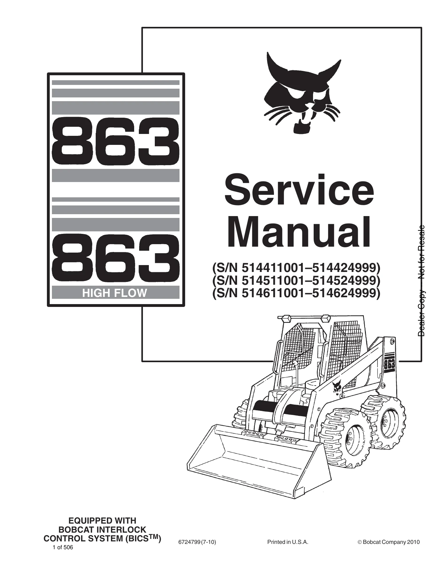
Bobcat 863 & 863H Skid Steer Loader Service Repair Manual (High Flow) - PDF Download — PDF page 1 preview
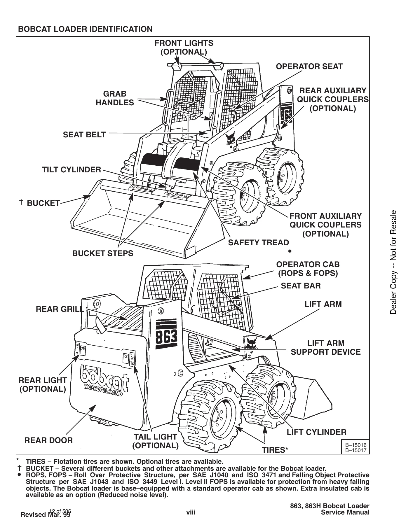
Bobcat 863 & 863H Skid Steer Loader Service Repair Manual (High Flow) - PDF Download — PDF page 12 preview
Bobcat 863 & 863H Skid Steer Loader Service Repair Manual (High Flow) - PDF Download — PDF page 51 preview

With this Bobcat 863 and 863H skid steer loader service manual you can perform routine maintenance on schedule, diagnose hydraulic, hydrostatic and electrical faults systematically, rebuild cylinders, pumps, motors and the engine to specification, and torque every critical fastener correctly the first time. Correct procedures and the correct specifications matter on machines like these — an over-torqued fitting, a missed shim or an incorrectly tensioned drive belt can turn a routine job into a repeat repair, and the diagnostic charts save hours of guesswork on the BICS and BOSS systems. The manual is delivered as an instant PDF download after payment, with no shipping and no waiting. Read it on a laptop or tablet in the shop, print the pages you need for the job in front of you, and keep the file as a permanent reference for the machine. Once you own it, you have the same service information for the life of the loader.
Reviews

There are no reviews yet.

Be the first to review “Bobcat 863 & 863H Skid Steer Loader Service Repair Manual (High Flow) – PDF Download”

What Our Customers Say

★★★★★ Live reviews from customers
Loading customer reviews...
0
    0
    Your Cart
    Your cart is emptyReturn to Shop
    🛒
    Recently Purchased
    🕒 verified order