
Bobcat G20E-7 G25E-7 G30E-7 G35EC-7 Forklift Service Manual – DSB4530E00
Original price was: $39.95.$23.95Current price is: $23.95.
411-page Bobcat service manual DSB4530E00 for G20E-7, G25E-7, G30E-7, G33E-7 and G35EC-7 forklifts – transmission, drive axle, hydraulics, mast, steering, brakes and schematics.
Description
Bobcat G20E-7 G25E-7 G30E-7 G35EC-7 Forklift Service Manual – DSB4530E00
This Bobcat G20E-7 G25E-7 G30E-7 G35EC-7 forklift service manual is the workshop document issued for the E-7 series counterbalance trucks. It covers models G20E-7, G25E-7, G30E-7, G33E-7 and G35EC-7 across 411 pages and nine chapters, explaining how every major system on the truck works, how it is taken apart, how it is rebuilt, and what the measured values should be at each stage. The foreword states its purpose plainly: explanations of the vehicle system plus instructions for disassembly and assembly.
File Details
- Manual type: Service Manual (workshop repair and overhaul)
- Document number: DSB4530E00
- Publication date: August 2023, Bobcat Company
- Revision: DSB4530E00, revised May 2025 (Section 8-7-2 diagram and speed control content amended)
- Brand: Bobcat
- Models covered: G20E-7, G25E-7, G30E-7, G33E-7, G35EC-7
- Engine: HMC 2.4 L four-cylinder, 2,359 cc, LP gas / gasoline
- Language: English
- Format: PDF
- Length: 411 pages
- Structure: Nine numbered chapters plus schematics
Chapters Covered
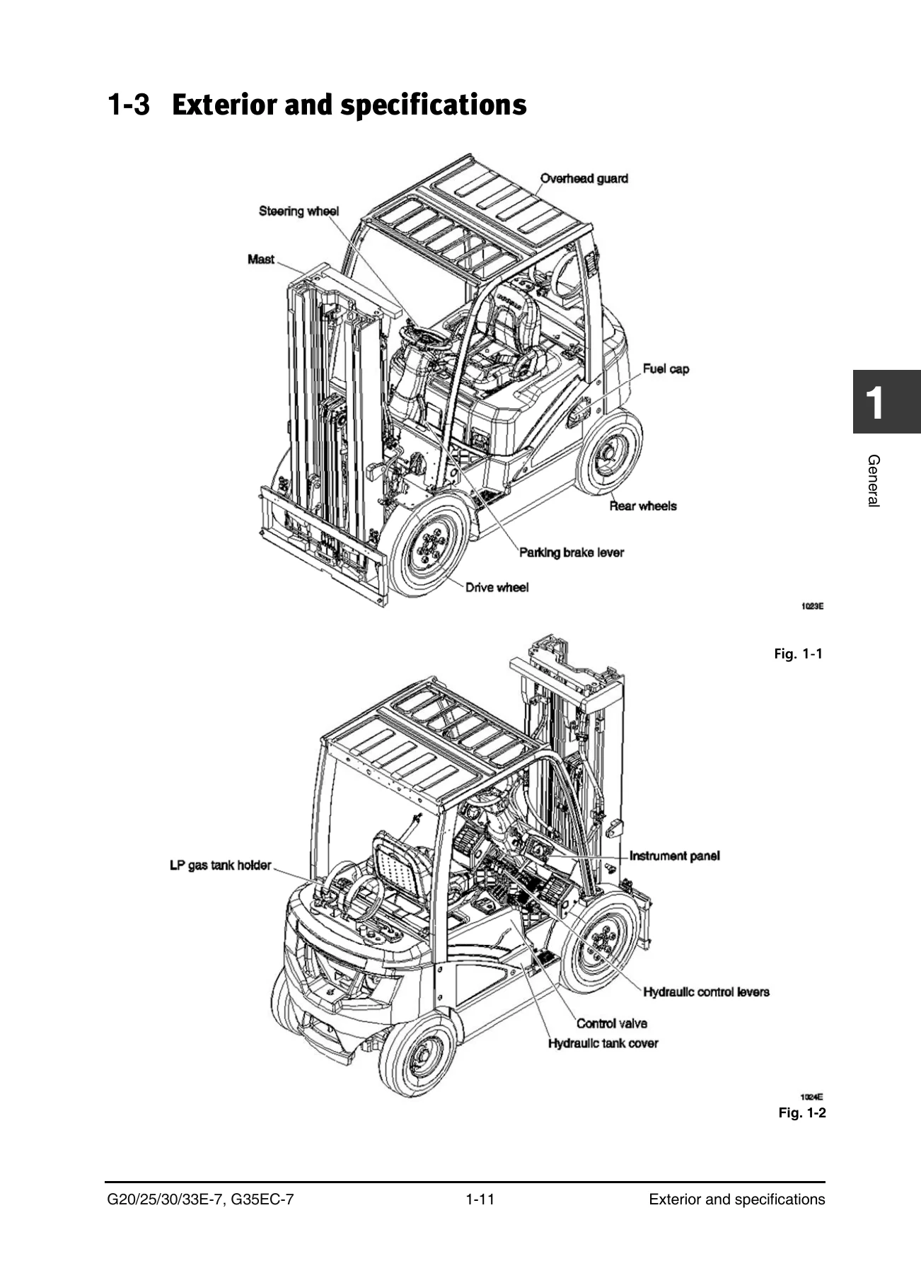
- 1 – General: how to use the manual, warning label definitions, major units, glossary, exterior and specifications, safety precautions, maintenance intervals, lubricants and capacities, disassembly/assembly instructions, standard torques for bolts, nuts and fittings
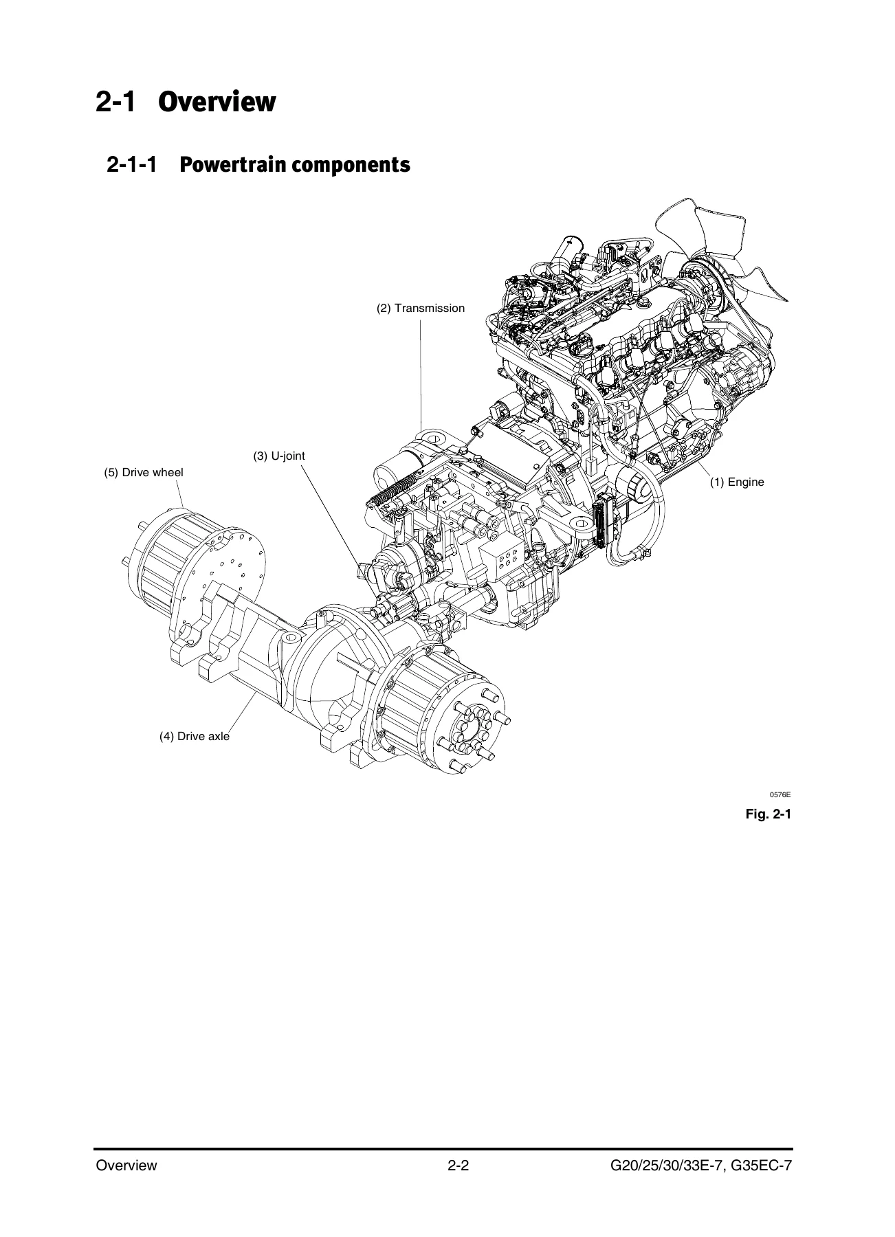
- 2 – Transmission: powertrain components, power flow, torque converter, converter stall test, transmission body, mechanical and hydraulic sections, transmission pressure test, inching pedal adjustment, engine-transmission removal and installation, housing disassembly and assembly, output gear assembly, input and counter gear assembly, valve assembly, electric control system and tests, troubleshooting
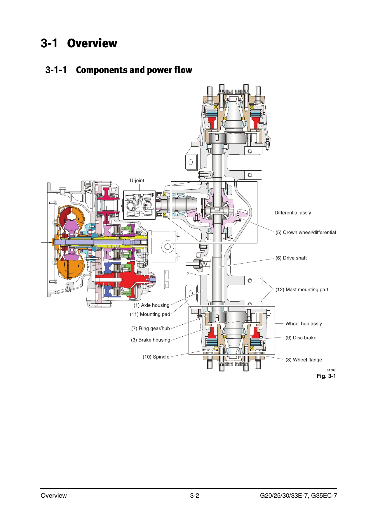
- 3 – Drive Axle: components and power flow, lubrication flow, tools needed, tightening torques, lubrication parts, drive axle body and accessories, drive wheel, U-joint, drive axle removal, wheel hub assembly, brake cover assembly, axle hub assembly, shaft and spindle, differential assembly, differential carrier, bevel pinion, differential removal and disassembly, troubleshooting
- 4 – Hydraulic System: components, oil flow, main hydraulic pump (exterior, operation, removal, disassembly), flow divider, priority valve operation, hydraulic tank and filter, suction strainer, return filter and air breather replacement, troubleshooting
- 5 – Lift/Tilt/Aux System: control valve, flow divider, LIFT/TILT/AUX sections, relief valve settings, needle valve emergency lowering, flow rate adjustment, control valve removal and disassembly, mast assembly, forks service, sideshifter service, chains service, tilt cylinders, primary lift cylinders, standard and secondary cylinders, carriage service, mast service, troubleshooting
- 6 – Steering System: components, oil flow, steering control group, steering unit operation, air removal, pressure check, steering wheel, steering column cover, steering unit removal and disassembly, steering operation group, rear wheel and hub, steer axle, steering link, knuckle, cylinder, troubleshooting
- 7 – Brake System: components, hydraulic and mechanical power flow, service brake assembly, pedal and master cylinder operation, brake pedal service and adjustment, master cylinder removal and disassembly, parking brake operation, adjustment, brake test, removal and installation, troubleshooting
- 8 – Frame / Miscellaneous: hood, floor plate, cabin and overhead guard, counterweight, ground speed control, OSS controller, automatic shift controller, new OSS, heating system, certified and non-certified muffler
- 9 – Schematics: hydraulic schematic, electric schematic, engine schematics (HMC 2.4 L T4_DF, T4_LP, Non-Cert_DF, Non-Cert_LP), electric schematic functional safety, instrument harness and chassis harness
Read end to end, the Bobcat G20E-7 G25E-7 G30E-7 G35EC-7 service manual works as a single reference for the whole truck rather than a collection of disconnected procedures. Each system chapter follows the same useful pattern: what the components are, how the system behaves when it is working, then the sequence for getting it apart, the torque and sealant figures that apply at each fastener, and a troubleshooting matrix for when the behaviour does not match. Because the E-7 series shares its transmission, drive axle and hydraulic architecture across the range, one manual serves the 2.0-tonne G20E-7 through to the 3.5-tonne G35EC-7 with model-specific values called out where they differ.
What the System Chapters Give You
The transmission chapter goes well beyond a removal guide. It walks through the torque converter’s internal fluid path, explains how the stator multiplies torque below a 0.85:1 turbine/impeller speed ratio, then shows the converter stall test with reference RPM figures and a cause table for high and low stall speeds. The hydraulic section diagrams the full oil circuit from sump through primary filter, main relief valve, inching valve, modulating valve and selector spools to the forward and reverse clutches, with pressure tap locations and a transmission pressure chart taken at 49 to 71 degrees C oil temperature.
The drive axle chapter covers the U-joint, wheel hub assemblies, differential carrier, bevel pinion and differential assembly as separate service sections. It includes a lubrication flow diagram fed by the transmission pump, a tightening torque illustration marking every critical fastener on the axle, and the shim-pack formulas needed to set bearing preload and crown wheel backlash to 0.15 to 0.20 mm.
On the front end, the lift/tilt/auxiliary chapter deals with the control valve block by block – flow divider, LIFT, TILT, AUX – and then works through the mast assembly itself. Forks get their own inspection criteria covering heel cracks, blade angle, straightness deviation and thickness wear limits. Chain wear is covered with a gauge method and a pitch-based calculation, and chain tension adjustment is described separately for standard, full free lift and full free triple masts. Tilt, primary and standard/secondary lift cylinders each have their own disassembly sequence with seal orientation notes.
Specifications, Torque Data and Reference Tables
Scattered through the manual are the numbers a technician actually works from. The general chapter tabulates dimensions, performance and weight data model by model, then lists lubricant viscosities against ambient temperature ranges and refill capacities for engine crankcase, cooling system, fuel tank, hydraulic and power steering system, transmission, drive axle housing and brake reservoir. Standard torque tables cover metric and inch bolts and nuts, taperlock studs, O-ring face seal fittings, 37-degree flared and straight thread O-ring fittings, 45-degree flared and inverted flare fittings, air conditioning fittings, tapered pipe thread fittings and hose clamp bands.
Individual chapters add their own service limits: relief valve settings for the main and auxiliary control valve blocks, steering relief pressure, converter relief and cooler bypass pressures, drive axle rolling torque and differential drag figures, wheel bearing adjustment torques, and brake pedal adjustment dimensions. Standard torques for the mast, carriage, chain anchors and suspension mounting bolts appear alongside the procedures that need them rather than only in the general chapter.
Electrical and Diagnostic Content
The electrical side is not an afterthought. The transmission electric control system has its own test procedures covering directional control switch continuity checks, harness inspection and solenoid plunger travel measurement. The frame chapter documents the OSS controller, the automatic shift controller with its direction inhibition speed settings and diagnostic codes, and the new operator sensing system with its seat belt sequence interlock, mast neutral detection, accel drive logic and gyro sensor. The schematics chapter closes the manual with hydraulic and electrical drawings including functional safety harness layouts for the instrument and chassis looms.
Who This Manual Suits
It is written for service engineers and mechanics rather than operators – the introduction notes it does not contain vehicle operation instructions. That makes it the right document for a workshop carrying out transmission overhauls, axle rebuilds, mast and cylinder service, hydraulic diagnostics or brake work on an E-7 series Bobcat. Owners running their own maintenance will still find the maintenance interval tables, lubricant specifications, chain wear limits and adjustment values directly usable.
Get the Full Bobcat G20E-7 G25E-7 G30E-7 G35EC-7 Service Manual
With the complete Bobcat G20E-7 G25E-7 G30E-7 G35EC-7 forklift service manual on hand you can strip and rebuild the torque converter and transmission, set differential bearing preload and crown wheel backlash correctly, chase a low converter charge pressure to its actual cause, re-shim a mast to zero clearance, adjust the parking brake to hold on a 15 percent grade, or work through the functional safety harness with the pin data in front of you. Doing that work from guesswork invites comeback failures and damage to components that are expensive to replace; doing it from the manufacturer’s own procedures, torque figures, sealant callouts and pressure charts is the difference between a repair that lasts and one that returns.
IMAGES PREVIEW
Your copy is delivered as an instant PDF download after checkout. No shipping, no waiting, no physical book to keep clean in a workshop. Open it on a laptop, tablet or phone at the machine, print the chapter you are working from, and keep the rest of the 411 pages intact for the next job.
Reviews
There are no reviews yet.