
Bobcat GC15S-9 GC18S-9 GC20SC-9 Forklift Service Manual – PDF
Original price was: $39.95.$24.95Current price is: $24.95.
367-page Bobcat service manual for GC15S-9, GC18S-9 and GC20SC-9 LP forklifts (DSB4483E01) – full disassembly, assembly, testing, torque and troubleshooting coverage.
Description
The Bobcat GC15S-9, GC18S-9 and GC20SC-9 Forklift Service Manual is the complete workshop reference for these three LP-gas cushion-tyre lift trucks, issued under document number DSB4483E01. Running to 367 pages, the manual works through the vehicle system by system: torque converter and powershift transmission, drive axle with its wet disc service and parking brakes, main hydraulic pump and priority valve, control valve and mast assembly, steering gear and steer axle, pedal group and master cylinder, and the frame-level components that hold it all together. Each chapter pairs illustrated disassembly and assembly procedures with the pressure readings, torque figures, shim calculations and service limits a technician needs to finish the job correctly rather than approximately.
File Details
- Manual type: Service Manual – workshop procedures, maintenance, testing and troubleshooting
- Brand: Bobcat
- Models covered: GC15S-9, GC18S-9, GC20SC-9
- Engines covered: PSI 4G63 (LP), GCT GK25 (LP)
- Document number: DSB4483E01
- Language: English
- Page count: 367 pages
- File format: PDF
Chapters Covered
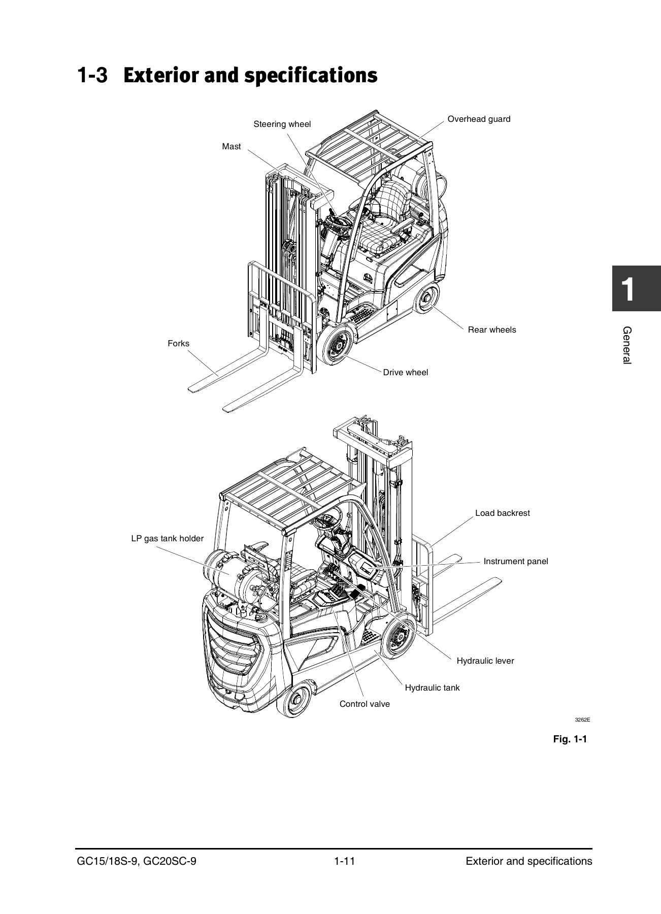
- 1 General – how to use this manual, glossary, exterior and specifications, safety precautions, maintenance, lubricants (LP fuel specifications, recommended viscosities and capacities, lubricant specifications), disassembly/assembly instructions, standard torques for bolts, nuts and fittings
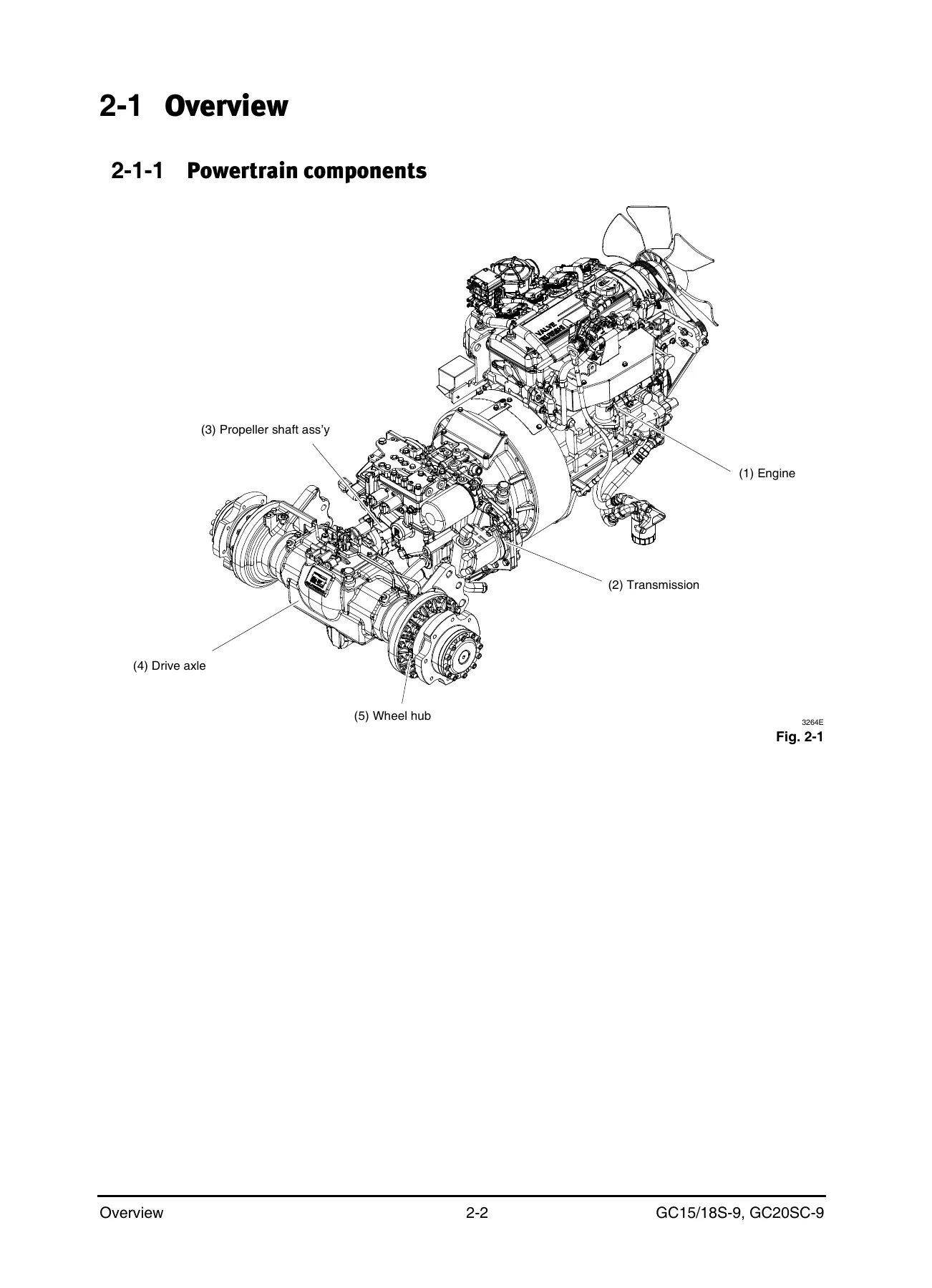
- 2 Transmission – powertrain components, transmission components and specifications, hydraulic operations, oil and filter change, converter stall test, transmission pressure testing, inching adjustment, transmission and engine removal/installation, transmission disassembly/assembly, transmission housing, stator hub assembly, charge PTO driven gear, main PTO driven gear, main output gear and clutch assembly, transmission case body, control valve, oil seal cover, troubleshooting
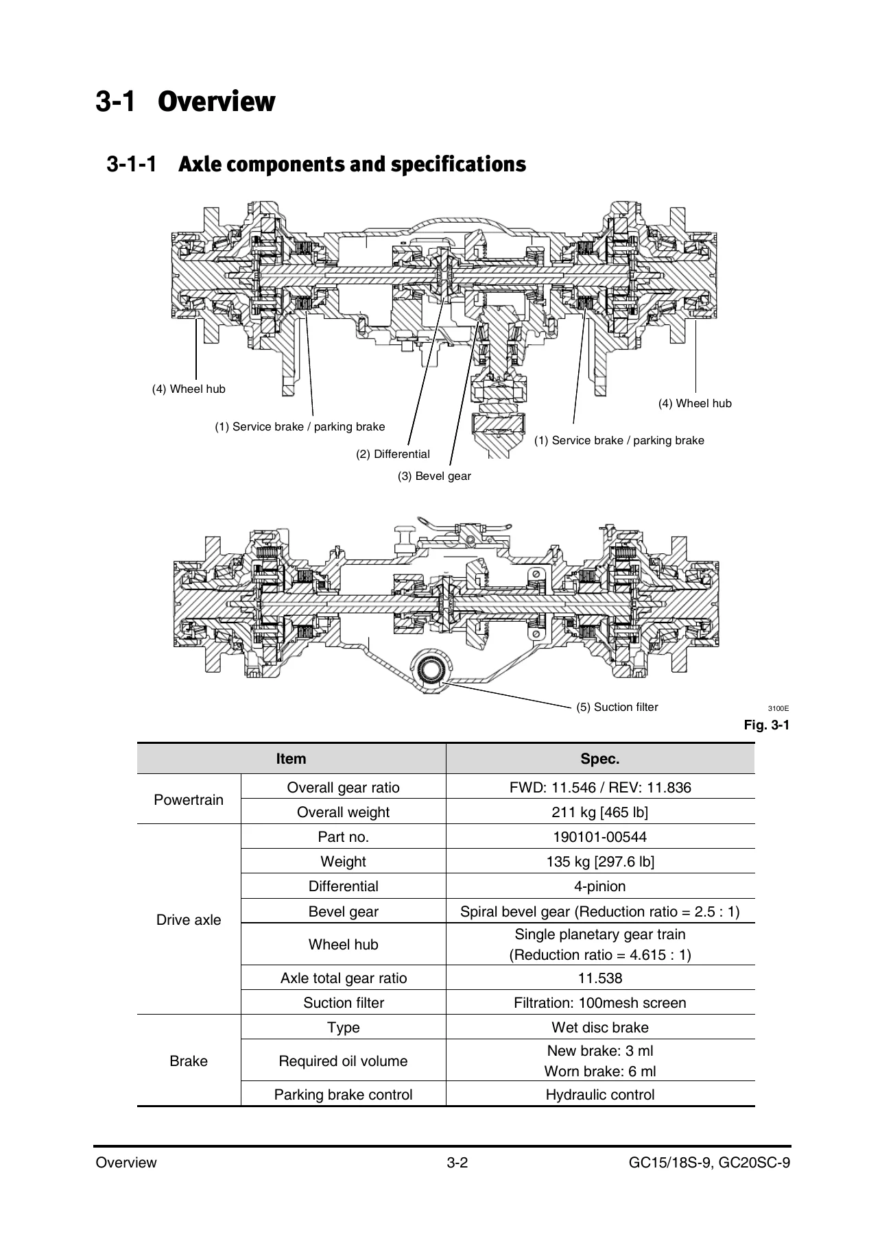
- 3 Drive axle – axle components and specifications, oil and filter change, drive wheel removal/installation, drive axle removal/installation, wheel hub and propeller shaft removal/installation, axle housing assembly, differential carrier assembly, differential assembly, brake piston assembly, brake block assembly, wheel hub section (LH/RH), carrier No. 2 assembly, troubleshooting
- 4 Hydraulic system – components, oil flow, main hydraulic pump exterior and specifications, pump operation, removal and installation, priority valve, hydraulic tank and filter, suction strainer, return filter and air breather replacement, troubleshooting
- 5 Lift/tilt/auxiliary system – components, oil flow, control valve exterior, specifications and operation, relief valve adjustment, needle valve for emergent lowering, control valve removal and disassembly, mast assembly, forks service, sideshifter service, chains service, tilt cylinders service, primary lift cylinders service, standard/secondary cylinders service, carriage service, mast service, troubleshooting
- 6 Steering system – components, oil flow, steering unit exterior and specifications, steering control mechanism, steering system air removal, steering system pressure check, steering wheel removal/installation, steering column assembly, steering unit removal/installation, steer axle, rear wheel turning angle adjustments, rear wheel and hub, link assembly and steering cylinder, steering cylinder disassembly, steering knuckle, king pin and bearing, troubleshooting
- 7 Brake system – components, hydraulic and mechanical operations, pedal group adjustments, removal and disassembly, master cylinder, air bleeding, brake block, parking brake test, manual release of the parking brake, service brake and parking brake troubleshooting
- 8 Frame / miscellaneous – hood, floor plate, FCU cover, side cover, radiator cover, step cover, overhead guard, counterweight, instrument panel exterior and function descriptions, automatic shift controller (ASC) exterior, operation, settings, diagnostic function, removal and installation
- 9 Schematics – powertrain hydraulic schematic, vehicle hydraulic schematic, electrical schematics, instrument harness, chassis harness
That chapter list only hints at the density of what sits inside. The transmission section alone covers the converter stall test with its reference RPM values, the full pressure-testing matrix for main, torque converter inlet, cooler inlet and clutch pressures, and the inching adjustment curve. The drive axle chapter takes the differential carrier apart, sets backlash against the correct adjust screws, reads gear contact patterns from marking ink, and calculates brake clearance and axle shaft shim thickness from measured dimensions. Hydraulic coverage includes relief valve adjustment figures for each of the three models, while the mast chapter walks through chain pitch measurement, chain wear limits, chain tension adjustment and roller bearing shimming for STD, FFL and FFT masts. The schematics chapter closes the book with powertrain hydraulic, vehicle hydraulic, electrical, instrument harness and chassis harness drawings.
Two LP Engines, Three Models, One Reference
The manual supports both engine variants offered in this range. The PSI 4G63 appears in the specifications tables with 2,450 rpm governed speed, a 1,730 +/- 100 stall RPM reference and a 0.9 mm spark plug gap, while the GCT GK25 carries its own displacement, torque, fuel consumption and 0.8-0.9 mm gap figures. Because the three trucks differ in load capacity and axle loading rather than architecture, a single manual covers GC15S-9, GC18S-9 and GC20SC-9 together, with model-specific values called out in the specification tables and relief pressure charts where they diverge – for example, main relief pressures listed separately for each model instead of one generic figure.
Service and Maintenance Intervals Included
The maintenance chapter sets out inspection criteria against service-hour intervals rather than vague recommendations, covering air intake service, tyre and wheel inspection, fuel system leak checking, LP regulator tar draining at its 200-hour interval, wheel bolt torque, carriage roller extrusion heights, mast channel lubrication, transmission and drive axle oil level, hydraulic and brake oil levels, and the first 50-100 hour transmission and axle oil and filter change. Later intervals bring in belt deflection under load, tilt cylinder and mast hinge lubrication, overhead guard bolt torque, steering and link lubrication, engine valve adjustment, lift chain abrasion testing with its wear-rate formula, U-joint and drive axle mounting checks, coolant hoses, LP regulator and mixer inspection, ignition and spark plug replacement with anti-seize and torque values, and fork inspection criteria with the 90 percent thickness rule.
Torque and Specification Data Throughout
Rather than a single appendix of numbers, this service manual embeds its specification data where the work happens. Standard torque tables for metric and inch fasteners sit in the general section alongside O-ring face seal fitting torques, hose clamp band torques, 37-degree flared and straight thread fitting torques, 45-degree flare fitting torques, air conditioning fitting torques and tapered pipe thread fitting torques. Beyond those standards, individual procedures carry their own values: transmission-to-engine bolts, flywheel-to-torque converter bolts, drive axle mounting bolts, mast mounting bolts, wheel nut torques, brake pipe torques, control valve flange bolts, plug torques, thrust screw torque and the various Loctite sealant callouts that accompany them.
What This Bobcat Service Manual Lets You Do
With this manual on hand you can pull the transmission and rebuild the forward and reverse clutch packs, re-shim the main output gear, set the differential backlash and verify gear contact, replace the wet disc brake packs and set brake clearance, remove and reinstall the mast on STD, FFL or FFT configurations, shim carriage and mast roller bearings to zero clearance, adjust chain tension and measure chain wear against the replacement threshold, test converter stall speed, run the full transmission pressure test, set main and auxiliary relief valves, bleed the steering and brake systems, and diagnose faults from the check lists rather than by guesswork. Correct procedures and the right torque and clearance values are what separate a repair that holds from one that comes back – the specifications here are the ones the machine was built around, not general workshop approximations.
IMAGES PREVIEW
Instant PDF Delivery
The manual is supplied as a downloadable PDF. There is no shipping, no waiting for a parcel and no physical book to keep clean in the workshop. Once payment clears you can open it immediately on a laptop, tablet or phone at the machine, print the pages you need for the job in front of you, and keep the rest of the file intact for the next repair. Whether you are servicing a single GC18S-9 in a small yard or maintaining a mixed fleet of all three models, the same file covers every job in the book from routine maintenance through to full component overhaul.
Reviews
There are no reviews yet.