Bobcat S590 Skid-Steer Loader Service Manual
$39.95 Original price was: $39.95.$24.95Current price is: $24.95.
Factory service manual for the Bobcat S590 Skid-Steer Loader (publication 6990176enUS). Contains detailed maintenance intervals, hydraulic and hydrostatic troubleshooting, electrical schematics, remote start diagnostics, and complete cylinder overhaul procedures for S/N ANMN11001, ANMP11001, AZND11001, AZNE11001, and B5N411001 & Above.
Description
Bobcat S590 Skid-Steer Loader Service Manual Overview
This comprehensive Bobcat S590 Skid-Steer Loader Service Manual (publication 6990176enUS) delivers full workshop repair, routine maintenance, and troubleshooting guidance for Bobcat S590 loaders across multiple serial number ranges. Built specifically for workshop mechanics, field service technicians, and owner-operators, this service manual provides step-by-step disassembly instructions, factory torque specifications, hydraulic schematics, and mechanical diagnostic instructions to keep your Bobcat S590 skid-steer loader operating safely and at peak performance.
File Details
- Manual Type: Service Manual
- Brand: Bobcat
- Model: S590 Skid-Steer Loader
- Document Number: 6990176enUS (08-22) (L)
- Publication Date: August 2022
- Covered Serial Numbers: S/N ANMN11001 & Above, S/N ANMP11001 & Above, S/N AZND11001 & Above, S/N AZNE11001 & Above, S/N B5N411001 & Above
- Language: English
- Page Count: 1302 pages
- File Format: PDF
Chapters Covered
- Foreword & Safety Instructions: Safety Guidelines, Fire Prevention Protocols, Welding and Grinding Precautions, Serial Number Locations, Delivery Report, Loader Component Identification
- Safety & Maintenance (Section 10-01):
- Lifting and Blocking the Loader
- Lift Arm Support Installation and Removal
- Operator Cab (ROPS/FOPS Inspection, Raising and Lowering Procedures, Cab Door Sensor, Special Applications Kit, Forestry Door and Window Kit)
- Transporting the Loader on a Trailer and Towing Guidelines
- Remote Start Tool Kits (MEL1563 Kit, Service Tool Kit 7217666, Loader Harness 6689747, and PC Diagnostic Interface)
- Service Schedule (10-Hour, 50-Hour, 100-Hour, 250-Hour, 500-Hour, 1000-Hour, and 24-Month Maintenance Intervals)
- Engine Air Cleaner Servicing (Service Code M0117, Dual Filter Element Replacement)
- Engine Cooling System (Earlier Models and Later Models Cleaning, Coolant Inspection, Propylene Glycol 53/47 Mixture Replacement)
- Fuel System (ASTM D975, EN590 Specifications, Biodiesel Blend Maintenance, Water Draining, Filter Replacement, and Priming Bulb Air Removal)
- Engine Lubrication System (API CI-4 / ACEA E7 Oil Specifications, Filter Servicing, and Remote Drain Hose Operation)
- Hydraulic / Hydrostatic System (Earlier and Later Models Fluid Inspection, ISO Viscosity Selection, Reservoir Draining, Main and Charge Filter Replacement, Breather Cap)
- Final Drive Transmission (Chaincase Fluid Level Check and Pump-Out Replacement)
- Bob-Tach Attachment Mounting System (Hand Lever and Power Bob-Tach Inspection, Wedge Engagement, and Linkage Maintenance)
- Lubricating the Loader (11 Defined Grease Locations including Pivot Pins and Cylinder Bushings)
- Tire Maintenance (Wheel Nut Torquing, Inflation Pressures, and Tire Rotation)
- Spark Arrester Muffler (100-Hour Chamber Cleanout Procedure)
- Pivot Pin Inspection and Retaining Bolt Torquing
- Loader Storage, Return to Service Procedures, and Machine Shutdown Protocols
- Emergency Cab Exits (Rear Window Latch and Rubber Cord Removal, Front Door Emergency Release and Hinge Reassembly)
- Seat Belt and Restraint System Inspection
Complete PDF Bookmark TreeComplete Bookmarks
The complete bookmarks in the “Bobcat S590 Skid-Steer Loader Service Manual” are as follows:
MAINTENANCE SAFETYp. 3CONTENTSp. 5+FOREWORDp. 7
FOREWORDp. 9SAFETY INSTRUCTIONSp. 11+FIRE PREVENTIONp. 13
Maintenancep. 13Operationp. 13Electricalp. 13Hydraulic Systemp. 13Fuelingp. 13Startingp. 13Spark Arrester Exhaust Systemp. 13Welding And Grindingp. 14Fire Extinguishersp. 14+SERIAL NUMBER LOCATIONSp. 15
Loader Serial Numberp. 15Engine Serial Numberp. 15DELIVERY REPORTp. 16LOADER IDENTIFICATIONp. 17+SAFETY AND MAINTENANCEp. 19
+LIFTING AND BLOCKING THE LOADERp. 23
Procedurep. 23+LIFT ARM SUPPORTp. 25
Descriptionp. 25Installingp. 26Removingp. 27+OPERATOR CABp. 29
Descriptionp. 29Raisingp. 30Loweringp. 32Cab Door Sensorp. 33Special Applications Kitp. 33Special Applications Kit Inspection And Maintenancep. 33Forestry Door And Window Kitp. 34Forestry Door And Window Kit Inspection And Maintenancep. 34+TRANSPORTING THE LOADER ON A TRAILERp. 35
Loading And Unloadingp. 35Fasteningp. 35+TOWING THE LOADERp. 37
Procedurep. 37+REMOTE START TOOL KIT – MEL1563p. 39
Remote Start Tool – MEL1563p. 39Service Tool Harness Communicator – MEL1566p. 41Remote Start Procedurep. 41+REMOTE START TOOL (SERVICE TOOL) KIT – 7217666p. 45
Descriptionp. 45Remote Start Tool (Service Tool) – 7022042p. 46Loader Service Tool Harness – 6689747p. 47Computer Service Tool Harness – 6689746p. 48Remote Start Procedurep. 49+SERVICE SCHEDULEp. 53
Maintenance Intervalsp. 53+ENGINE AIR CLEANERp. 55
Replacing Filtersp. 55+ENGINE COOLING SYSTEM (EARLIER MODELS)p. 57
Maintenance Platformp. 57Cooling System Identificationp. 57Cleaningp. 58Checking And Adding Coolantp. 60Removing And Replacing Coolantp. 61+ENGINE COOLING SYSTEM (LATER MODELS)p. 63
Maintenance Platformp. 63Cleaningp. 63Checking And Adding Coolantp. 65Removing And Replacing Coolantp. 66+FUEL SYSTEMp. 69
Fuel Specificationsp. 69Biodiesel Blend Fuelp. 69Filling The Fuel Tankp. 70Fuel Filterp. 71Removing Air From The Fuel Systemp. 72+ENGINE LUBRICATION SYSTEMp. 73
Checking And Adding Engine Oilp. 73Engine Oil Chartp. 73Removing And Replacing Oil And Filterp. 74+HYDRAULIC / HYDROSTATIC SYSTEM (EARLIER MODELS)p. 75
Checking And Adding Fluidp. 75Hydraulic / Hydrostatic Fluid Chartp. 75Removing And Replacing Hydraulic Fluidp. 76Removing And Replacing Hydraulic / Hydrostatic Filterp. 78Removing And Replacing Hydraulic Charge Filterp. 79Replacing Reservoir Breather Capp. 80+HYDRAULIC / HYDROSTATIC SYSTEM (LATER MODELS)p. 81
Checking And Adding Fluidp. 81Hydraulic / Hydrostatic Fluid Chartp. 81Removing And Replacing Hydraulic Fluidp. 82Removing And Replacing Hydraulic / Hydrostatic Filterp. 84Removing And Replacing Hydraulic Charge Filterp. 85Replacing Reservoir Breather Capp. 86+FINAL DRIVE TRANSMISSION (CHAINCASE)p. 87
Checking And Adding Fluidp. 87Removing And Replacing Fluidp. 87+BOB-TACH (HAND LEVER)p. 89
Inspection And Maintenancep. 89+BOB-TACH (POWER)p. 91
Inspection And Maintenancep. 91+LUBRICATING THE LOADERp. 93
Lubrication Locationsp. 93+TIRE MAINTENANCEp. 97
Wheel Nutsp. 97Rotatingp. 97Mountingp. 98+SPARK ARRESTER MUFFLERp. 99
Cleaning Procedurep. 99+PIVOT PINSp. 101
Inspection And Maintenancep. 101+LOADER STORAGE AND RETURN TO SERVICEp. 103
Storagep. 103Return To Servicep. 103+STOPPING THE ENGINE AND LEAVING THE LOADERp. 105
Procedurep. 105+EMERGENCY EXITp. 107
Rear Window Identificationp. 107Rear Window Removal (Latches)p. 107Rear Window Removal (Rubber Cord)p. 107External Access (Rear Window With Latches)p. 108External Access (Rear Window With Rubber Cord)p. 108Front Doorp. 108+SEAT BELTp. 111
Inspection And Maintenancep. 111+HYDRAULIC SYSTEMp. 113
+HYDRAULIC / HYDROSTATIC SCHEMATICSp. 119
+MANUAL WITH NO OPTIONSp. 119
S/N ANMN11001 & Abovep. 119S/N ANMP11001 & Abovep. 119S/N AZND11001 & Abovep. 119S/N AZNE11001 & Abovep. 119S/N B5N411001 & Abovep. 119+MANUAL WITH ALL OPTIONSp. 121
S/N ANMN11001 – ANMN15407p. 121S/N ANMP11001 AND ABOVEp. 121S/N AZND11001 – AZND11066p. 121S/N AZNE11001 & Abovep. 121S/N ANMN15408 – ANMN15865p. 123S/N AZND11067- AZND11103p. 123S/N ANMN15866 & Abovep. 125S/N AZND11104 & Abovep. 125S/N B5N411001 & Abovep. 125+SJC WITH NO OPTIONSp. 127
S/N ANMN11001 – ANMN17100p. 127S/N ANMP11001 & Abovep. 127S/N AZND11001 – AZND12600p. 127S/N AZNE11001 & Abovep. 127S/N ANMN17101 & Abovep. 129S/N AZND12601 & Abovep. 129S/N B5N411001 & Abovep. 129+SJC WITH ALL OPTIONSp. 131
S/N ANMN11001 – ANMN15407p. 131S/N ANMP11001 & Abovep. 131S/N AZND11001 – AZND11066p. 131S/N AZNE11001 & Abovep. 131S/N ANMN15408 – ANMN15865)p. 133S/N AZND11067 – AZND11103p. 133S/N ANMN15866 – ANMN17100p. 135S/N AZND11104 – AZND12600p. 135S/N ANMN17101 & Abovep. 137S/N AZND12601 & Abovep. 137S/N B5N411001 & Abovep. 137+HYDRAULIC SYSTEM INFORMATIONp. 139
Glossary Of Hydraulic / Hydrostatic Symbolsp. 139Troubleshootingp. 143+CYLINDER (LIFT)p. 145
Testingp. 145Removal And Installationp. 146Parts Identificationp. 150Disassemblyp. 151Assemblyp. 153+CYLINDER (TILT)p. 157
Testingp. 157Removal And Installationp. 158Base End Pivot Pin Removal And Installationp. 159Parts Identificationp. 160Disassemblyp. 161Assemblyp. 163+CYLINDER (LIFT) (S/N AZND11152 & ABOVE)p. 167
Testingp. 167Removal And Installationp. 168Parts Identificationp. 172Disassemblyp. 173Assemblyp. 175+CYLINDER (TILT) (S/N AZND11152 & ABOVE)p. 179
Testingp. 179Removal And Installationp. 180Base End Pivot Pin Removal And Installationp. 181Parts Identificationp. 182Disassemblyp. 183Assemblyp. 185+CYLINDER (BOB-TACH)p. 189
Testingp. 189Removal And Installationp. 190Parts Identificationp. 191Disassemblyp. 192Assemblyp. 194+MAIN RELIEF VALVEp. 197
Descriptionp. 197Testingp. 198Adjustingp. 200Removal And Installationp. 201+HYDRAULIC CONTROL VALVE (STANDARD)p. 203
Descriptionp. 203Removal And Installationp. 204Mount Bracket Removal And Installationp. 207Identification Chartp. 208Lift Load Check Valve Removal And Installationp. 209Load Check Valve Removal And Installation (Tilt And Auxiliary)p. 210Anti-Cavitation Valve Removal And Installation (Lift, Rod End)p. 211Port Relief / Anti-Cavitation Valve Removal And Installation (Lift, Base End)p. 211Port Relief / Anti-Cavitation Valve Removal And Installation (Tilt, Base End)p. 212Port Relief / Anti-Cavitation Valve Removal And Installation (Tilt, Rod End)p. 212Port Relief Valve Removal And Installationp. 213Plug Removal And Installationp. 215Rubber Boot Removal And Installationp. 216End Cap Block Removal And Installationp. 216Lift Spool And Detent Removal And Installationp. 217Tilt Spool Removal And Installationp. 225Auxiliary Spool Removal And Installationp. 227Auxiliary Solenoid Removal And Installationp. 228Solenoid Removal And Installationp. 229Lock Valve Removal And Installationp. 230Lift Arm Bypass Orifice Removal And Installationp. 232Main Relief Valve Removal And Installationp. 232Check Valve Removal And Installationp. 233+HYDRAULIC CONTROL VALVE (ACS) (JC) OR (SJC)p. 235
Descriptionp. 235Removal And Installationp. 235Actuator Removal And Installation (In Loader)p. 239Actuator Removal And Installation (Out Of Loader)p. 241Identification Chartp. 244Mount Bracket Removal And Installationp. 245Lift Load Check Valve Removal And Installationp. 245Load Check Valve Removal And Installation (Tilt And Auxiliary)p. 246Anti-Cavitation Valve Removal And Installation (Lift, Rod End)p. 247Port Relief / Anti-Cavitation Valve Removal And Installation (Lift, Base End)p. 247Port Relief / Anti-Cavitation Valve Removal And Installation (Tilt, Base End)p. 248Port Relief / Anti-Cavitation Valve Removal And Installation (Tilt, Rod End)p. 248Port Relief Valve Removal And Installationp. 249Plug Removal And Installationp. 251End Cap Block Removal And Installationp. 252Lift Spool Removal And Installationp. 252Lift Spool Disassembly And Assemblyp. 254Tilt Spool Removal And Installationp. 255Auxiliary Spool Removal And Installationp. 257Auxiliary Solenoid Removal And Installationp. 258Solenoid Removal And Installationp. 259Lock Valve Removal And Installationp. 260Lift Arm Bypass Orifice Removal And Installationp. 262Main Relief Valve Removal And Installationp. 262Check Valve Removal And Installationp. 263+LIFT ARM BYPASS CONTROL VALVEp. 265
Descriptionp. 265Testingp. 265Removal And Installationp. 266Bracket Removal And Installationp. 267Disassembly And Assemblyp. 267+HYDRAULIC PUMPp. 269
Descriptionp. 269Pump Test At Quick Couplersp. 270Direct Pump Test (Standard Section)p. 272Direct Pump Test (Charge Section)p. 274Removal And Installationp. 276Hydraulic Pump Startupp. 278Parts Identificationp. 279Disassembly And Assemblyp. 280+3HYDRAULIC PUMP (HIGH FLOW)p. 281
Descriptionp. 281Pump Test At Quick Couplersp. 282Direct Pump Test (Standard Section)p. 284Direct Pump Test (Charge Section)p. 285Direct Pump Test (High Flow Section)p. 287High Flow Relief Valve Adjustmentp. 289High Flow Relief Valve Removal And Installationp. 291Solenoid Removal And Installationp. 292Removal And Installationp. 293Hydraulic Pump Startupp. 295Parts Identificationp. 296Disassembly And Assemblyp. 297+HYDRAULIC / HYDROSTATIC FILTERSp. 299
Descriptionp. 299Housing Removal And Installationp. 299+HYDRAULIC FLUID RESERVOIRp. 301
Descriptionp. 301Removal And Installationp. 301Hydraulic Fluid Screenp. 302+OIL COOLER (EARLIER MODELS)p. 303
Descriptionp. 303Removal And Installationp. 303+OIL COOLER (LATER MODLES)p. 305
Removal And Installationp. 305+BUCKET POSITION VALVEp. 307
Descriptionp. 307Solenoid Removal And Installationp. 307Solenoid Testingp. 308Removal And Installationp. 309Disassembly And Assemblyp. 311+REAR AUXILIARY DIVERTER VALVEp. 313
Descriptionp. 313Solenoid Testingp. 313Removal And Installationp. 314Disassembly And Assemblyp. 315+BOB-TACH (POWER) BLOCK (S/N ANMN11001 – ANMN15407)p. 321
Descriptionp. 321Removal And Installationp. 321Disassembly And Assemblyp. 323+BOB-TACH (POWER) BLOCK (S/N ANMN15408 & ABOVE)p. 331
Descriptionp. 331Testing Relief Valvep. 332Removal And Installationp. 334Disassembly And Assemblyp. 336+FRONT AUXILIARY HYDRAULIC COUPLER BLOCKp. 341
Descriptionp. 341Removal And Installationp. 342Disassembly And Assembly (FFI/FI)p. 342Disassembly And Assembly (FFH/FH)p. 344+AUTOMATIC RIDE CONTROLp. 347
Descriptionp. 347Removal And Installationp. 348Checking The Pressure In The Accumulatorp. 351Adding Nitrogen To The Accumulatorp. 353+HYDROSTATIC SYSTEMp. 355
+HYDROSTATIC SYSTEM INFORMATIONp. 357
Descriptionp. 357Troubleshootingp. 358+HYDROSTATIC DRIVE MOTORp. 359
Descriptionp. 359Removal And Installationp. 359Parts Identificationp. 362Disassembly And Assemblyp. 363+HYDROSTATIC DRIVE MOTOR (TWO-SPEED)p. 369
Descriptionp. 369Removal And Installation (Left Side)p. 370Removal And Installation (Right Side)p. 373Parts Identificationp. 376Disassemblyp. 377Assemblyp. 390+HYDROSTATIC MOTOR CARRIERp. 405
Descriptionp. 405Shaft Seal Removal And Installationp. 406Removal And Installationp. 408Parts Identificationp. 410Disassemblyp. 411Assemblyp. 413+HYDROSTATIC MOTOR CARRIER (TWO-SPEED)p. 417
Descriptionp. 417Shaft Seal Removal And Installationp. 418Removal And Installationp. 420Parts Identificationp. 422Disassemblyp. 423Assemblyp. 425+CHARGE PRESSUREp. 429
Descriptionp. 429Testingp. 430Adjustingp. 432Sender Removal And Installationp. 434+HYDROSTATIC PUMPp. 435
Descriptionp. 435Removal And Installationp. 436Hydrostatic Pump Startupp. 437Replenishing / High Pressure Relief Valve Removal And Installationp. 438Parts Identification (Left Half)p. 439Parts Identification (Right Half)p. 440Disassemblyp. 441Assemblyp. 448+HYDROSTATIC PUMP (JC) OR (SJC)p. 455
Descriptionp. 455Hydraulic Controller Removal And Installationp. 456Removal And Installationp. 458Hydrostatic Pump Startupp. 460Parts Identificationp. 461High Pressure Relief And Bypass Valvep. 462Charge Relief Valvep. 463Disassembly And Assemblyp. 464Mechanical Neutral Adjustmentp. 477Hydraulic Controller Neutral Adjustmentp. 480+HYDROSTATIC PUMP (JC) OR (SJC) (S/N ANMN17101 & ABOVE)p. 483
Descriptionp. 483Port Locations And Gauge Installationp. 484Removal And Installationp. 485Hydrostatic Pump Startupp. 487Parts Identificationp. 488High Pressure Relief And Bypass Valvep. 491Charge Pressure Relief Valvep. 492Disassembly And Assemblyp. 493Mechanical Neutral Adjustmentp. 505Hydraulic Controller Neutral Adjustmentp. 507+DRIVE BELTp. 509
Belt Adjustmentp. 509Belt Replacementp. 510+TWO-SPEEDp. 513
Valve Block Removal And Installationp. 513Valve Block Disassembly And Assemblyp. 514+DRAIN MANIFOLDp. 515
Descriptionp. 515Drain Manifold Removal And Installationp. 515+DRIVE SYSTEMp. 517
+BRAKEp. 519
Descriptionp. 519Disc Removal And Installationp. 519+DRIVE COMPONENTSp. 521
Descriptionp. 521Axle Seal Removal And Installationp. 522Axle, Sprocket And Bearings Removal And Installationp. 524Chain Removal And Installationp. 529+CHAINCASEp. 531
Descriptionp. 531Front Cover Removal And Installationp. 531Center Cover Removal And Installationp. 532Rear Cover Removal And Installationp. 533+MAINFRAMEp. 535
+SEAT BARp. 539
Descriptionp. 539Removal And Installationp. 539Disassembly And Assemblyp. 540Compression Spring Disassembly And Assemblyp. 541+OPERATOR CABp. 543
Gas Spring Removal And Installationp. 543Gas Spring Bracket Disassembly And Assemblyp. 544Removal And Installationp. 544+OPERATOR SEATp. 547
Removal And Installationp. 547Seat Belt Removal And Installation (Retractable)p. 547Seat Belt And Bracket Removal And Installation (Standard)p. 548Seat Belt Bracket Removal And Installationp. 548+OPERATOR SEAT (SUSPENSION)p. 549
Removal And Installationp. 549Slide Rail Removal And Installationp. 549Seat Belt Removal And Installationp. 550Lower Cushion Removalp. 550Lower Cushion Installationp. 551Back Cushion Removal And Installationp. 551Shock Removal And Installationp. 5523-Point Seat Belt Removal And Installationp. 552+BOB-TACH (HAND LEVER)p. 555
Descriptionp. 555Removal And Installationp. 555Lever And Wedge Disassembly And Assemblyp. 557Pivot Pin Bushing And Seal Removal And Installationp. 559+BOB-TACH (POWER)p. 561
Descriptionp. 561Removal And Installationp. 561Lever And Wedge Disassembly And Assemblyp. 564Pivot Pin Bushing And Seal Removal And Installationp. 566+LIFT ARMSp. 567
Stabilizer Bar Removal And Installationp. 567Link Removal And Installationp. 568Removal And Installationp. 569+REAR GRILLEp. 573
Removingp. 573Installingp. 573+REAR DOOR (TAILGATE)p. 575
Removal And Installationp. 575Striker Removal And Installationp. 576Striker Disassembly And Assemblyp. 576Striker Adjustingp. 577Latch Removal And Installationp. 577+FUEL TANKp. 579
Removal And Installationp. 579Fuel Level Sender Removal And Installationp. 582Fuel Fill Screen Removal And Installationp. 582+CONTROL PEDALS AND LINKAGESp. 583
Descriptionp. 583Pedal Removal And Installationp. 583Linkage Removal And Installationp. 584Pedal (Adjusting)p. 585Floor Pan Removal And Installationp. 586+CONTROL PEDALS AND LINKAGES (ACS)p. 587
Descriptionp. 587Pedal Removal And Installationp. 587Linkage Removal And Installationp. 588Pedal (Adjusting)p. 588Floor Pan Removal And Installationp. 589+CONTROL PANELp. 591
Descriptionp. 591Removal And Installationp. 592Disassembly And Assemblyp. 593Linkage Removal And Installationp. 597Pintle Arm Disassembly And Assemblyp. 601Linkage Neutral (Adjusting)p. 602Linkage Travel (Adjusting)p. 606Shock Removal And Installationp. 610+CONTROL PANEL (JC) OR (SJC)p. 611
Descriptionp. 611Removal And Installationp. 611+CONTROL HANDLE / LEVERp. 613
Descriptionp. 613Lever Removal And Installationp. 613Boot Removal And Installationp. 614+CONTROL HANDLE / LEVER (ACS)p. 615
Descriptionp. 615Handle Sensor Removal And Installationp. 615Handle Removal And Installationp. 618Handle Disassembly And Assemblyp. 619Lever Removal And Installationp. 619Boot Removal And Installationp. 620+CONTROL HANDLE / LEVER (JC) OR (SJC)p. 621
Descriptionp. 621Joystick Testingp. 621Joystick Removal And Installationp. 622+ACCESS PANEL (INSIDE)p. 623
Removal And Installation (Left)p. 623Removal And Installation (Right)p. 623+ACCESS PANEL (INSIDE) (JC) OR (SJC)p. 625
Removal And Installation (Left)p. 625Removal And Installation (Right)p. 625+WINDOW (REAR)p. 627
Rear Window Identificationp. 627Rear Window Removal (Latches)p. 627Rear Window Removal (Rubber Cord)p. 627Disassembly And Assemblyp. 628External Access (Rear Window With Latches)p. 629External Access (Rear Window With Rubber Cord)p. 629+WINDOW (TOP)p. 631
Removal And Installationp. 631+WINDOW (SIDE)p. 633
Removal And Installationp. 633+CAB DOORp. 635
Descriptionp. 635Removal And Installationp. 635Disassembly And Assemblyp. 636Aligningp. 637Adjustingp. 638Checking Operationp. 638+ARMRESTp. 639
Descriptionp. 639Removal And Installationp. 640Disassembly And Assemblyp. 641+LEFT SIDE LOWER PANELp. 643
Removal And Installationp. 643Disassembly And Assemblyp. 645+RIGHT SIDE LOWER PANELp. 647
Removal And Installationp. 647Disassembly And Assemblyp. 648+HEADLINERp. 651
Removal And Installationp. 651+ELECTRICAL SYSTEMp. 653
+ELECTRICAL SCHEMATICSp. 659
+MANUAL MACHINEp. 659
S/N ANMN11001 – ANMN11590p. 659S/N ANMP11001 – ANMP11005p. 659S/N AZND11001 – AZND11042p. 659S/N AZNE11001 – AZNE11039p. 659S/N ANMN11591 – ANMN13300p. 672S/N ANMP11006 & Abovep. 672S/N AZNE11040 – AZNE11060p. 672S/N ANMN13301 – ANMN15170 &ANMN15172 & ANMN15173 &ANMN15176 – ANMN15327p. 685S/N AZND11043 – AZND11057p. 685S/N AZNE11061 – AZNE11130p. 685S/N AZND11058 – AZND11103p. 698S/N AZNE11131 – AZNE11162p. 698+STANDARD MACHINEp. 711
S/N ANMN15760 through ANMN16099p. 711S/N AZND11104 through AZND12000p. 711S/N AZNE11163 & Abovep. 711S/N ANMN16100 & Abovep. 725S/N AZND12001 through AZND12600p. 739S/N AZND12601 & Abovep. 753S/N B5N411001 & Abovep. 753+ACS / SJC MACHINEp. 767
S/N ANMN11001 – ANMN11590p. 767S/N ANMP11001 – ANMP11005p. 767S/N AZND11001 – AZND11042p. 767S/N AZNE11001 – AZNE11039p. 767S/N ANMN11591 – ANMN13300p. 782S/N ANMP11006 & Abovep. 782S/N AZNE11040 – AZNE11060p. 782S/N AZND11043 – AZND11057p. 797S/N AZNE11061 – AZNE11130p. 797S/N ANMN15171 & ANMN15174- ANMN15175 & ANMN15328 -ANMN15759p. 812S/N AZND11058 – AZND11103p. 812S/N AZNE11131 – AZNE11162p. 812S/N ANMN15760 through ANMN16099p. 827S/N AZND11104 through AZND12000p. 827S/N AZNE11163 & Abovep. 827S/N ANMN16100 & Abovep. 843S/N AZND12001 through AZND12600p. 861+SJC MACHINEp. 877
S/N AZND12601 & Abovep. 877S/N B5N411001 & Abovep. 877WIRING SCHEMATIC (KIT AND OPTION HARNESS) ALL MODELSp. 893+ELECTRICAL SYSTEM INFORMATIONp. 899
Glossary Of Electrical Symbolsp. 899Standard Cab Harness Connectorsp. 902Deluxe Cab Harness Connectorsp. 903Mainframe Harness Connectors – Manual Controlsp. 904Mainframe Harness Connectors – (JC) or (SJC)p. 905Descriptionp. 906Troubleshootingp. 907Fuse And Relay Location / Identificationp. 908Solenoid Testingp. 910+BATTERYp. 911
Removal And Installationp. 911Battery Maintenancep. 912Maintaining Battery Charge Levelp. 912Battery Service During Machine Storagep. 912Battery Testingp. 913Battery Chargingp. 913Using A Booster Battery (Jump Starting)p. 914+ALTERNATORp. 915
Belt Adjustmentp. 915Belt Replacementp. 915Alternator Voltage Testingp. 916Low Voltage Testingp. 916High Voltage Testingp. 917Removal And Installationp. 918Parts Identificationp. 919+STARTERp. 921
Testingp. 921Removal And Installationp. 921Parts Identificationp. 922+INSTRUMENT PANELSp. 923
Left Panelp. 923Display Screenp. 925Right Panel (Standard Key Panel)p. 926Right Panel (Keyless Start Panel)p. 927Right Panel (Deluxe Instrumentation Panel)p. 928Left Switch Panelp. 930Right Switch Panelp. 930Left Side Lower Panelp. 931Right Side Lower Panelp. 931Left Panel Removal And Installationp. 932Right Panel (Standard Key Panel) Removal And Installationp. 932Right Panel (Keyless Start Panel) Removal And Installationp. 933Right Panel (Deluxe Instrumentation Panel) Removal And Installationp. 933Key Switch Disassembly And Assemblyp. 934Alarm Disassembly And Assemblyp. 934Left Switch Panel Removal And Installationp. 935Right Switch Panel Removal And Installationp. 935+LIGHTSp. 937
Front Removal And Installationp. 937Rear Removal And Installationp. 938Cab Light Removal And Installationp. 938+BOBCAT CONTROLLERS (GATEWAY AND AUXILIARY)p. 939
Descriptionp. 939Connector Identificationp. 940Removal And Installationp. 946+BOBCAT CONTROLLER (ACS)p. 947
Descriptionp. 947Connector And Wire Identificationp. 948Removal And Installationp. 949+BOBCAT CONTROLLER (JC) OR (SJC) (DRIVE)p. 951
Descriptionp. 951Connector Identificationp. 952Removal And Installationp. 954+DIAGNOSTIC SERVICE CODESp. 955
Viewing Service Codesp. 955Service Codes Listp. 956+BOBCAT INTERLOCK CONTROL SYSTEM (BICS™)p. 963
Descriptionp. 963Inspecting The BICS™ (Engine STOPPED – Key ON)p. 964Inspecting Deactivation Of The Auxiliary Hydraulics System (Engine STOPPED – Key ON)p. 964Inspecting The Seat Bar Sensor (Engine RUNNING)p. 964Inspecting The Traction Lock And Parking Brake (Engine RUNNING)p. 964Inspecting The Lift Arm Bypass Controlp. 964Inspecting Deactivation Of Lift And Tilt Functions (ACS), (JC), or (SJC)p. 964Troubleshootingp. 965+SEAT BAR SENSORp. 967
Descriptionp. 967Troubleshootingp. 967Testingp. 968Removalp. 969Installationp. 971Bobcat Interlock Control System (BICS™) Circuit Testp. 972+TRACTION LOCKp. 975
Descriptionp. 975Troubleshootingp. 976Inspectingp. 977+CONTROL SYSTEM (ACS)p. 979
Descriptionp. 979Troubleshootingp. 980Handle Sensor Connector Disassembly And Assemblyp. 981Switch Handle Removalp. 982Switch Handle Installationp. 984Actuator Connector Disassembly And Assemblyp. 987Handle Lock Solenoid Removal And Installationp. 988Handle Lock Solenoid Disassembly And Assemblyp. 988Foot Sensor Removal And Installationp. 989Foot Sensor Disassembly And Assemblyp. 990Foot Sensor Lock Solenoid Removal And Installationp. 990+ELECTRICAL / HYDRAULIC CONTROLSp. 991
Identification Chartp. 991Descriptionp. 992Identification Chart ACD Group 0p. 993Identification Chart ACD Group 1p. 994Identification Chart ACD Group 2p. 995Identification Chart ACD Group 3p. 996+ELECTRICAL / HYDRAULIC CONTROLS (ACS)p. 997
Identification Chartp. 997Descriptionp. 998Identification Chart ACD Group 0p. 999Identification Chart ACD Group 1p. 1000Identification Chart ACD Group 2p. 1001Identification Chart ACD Group 3p. 1002+ELECTRICAL / HYDRAULIC CONTROLS (JC) OR (SJC)p. 1003
Identification Chartp. 1003Descriptionp. 1004Identification Chart ACD Group 0p. 1005Identification Chart ACD Group 1p. 1006Identification Chart ACD Group 2p. 1007Identification Chart ACD Group 3p. 1008+SERVICE PC (LAPTOP COMPUTER)p. 1009
Connecting Remote Start Toolp. 1009Connecting Remote Start Tool (Service Tool)p. 1009+CALIBRATIONp. 1011
Descriptionp. 1011Actuator Testingp. 1011Lift And Tilt Calibration (JC) OR (SJC)p. 1014Hydrostatic Pump Calibration (JC) or (SJC)p. 1016Lift And Tilt Calibration (ACS)p. 1021+STEERING DRIFT COMPENSATION (OPERATOR MODE)p. 1023
Descriptionp. 1023Operationp. 1023+STEERING DRIFT COMPENSATION (SERVICE MODE)p. 1025
Descriptionp. 1025Operationp. 1025+FLYWHEEL RPM SENSORp. 1027
Descriptionp. 1027Removalp. 1027Installationp. 1028+CONTROL PANEL SETUPp. 1029
Right Panel Setup (Deluxe Instrumentation Panel)p. 1029+PASSWORD SETUP (DELUXE INSTRUMENTATION PANEL)p. 1033
Password Descriptionp. 1033Changing The Owner Passwordp. 1033Changing The User Passwordsp. 1034Password Lockout Featurep. 1034+PASSWORD SETUP (KEYLESS START PANEL)p. 1035
Password Descriptionp. 1035Changing The Owner Passwordp. 1035Password Lockout Featurep. 1035+MAINTENANCE CLOCKp. 1037
Descriptionp. 1037Setupp. 1038Resetp. 1041+BACK-UP ALARM SYSTEMp. 1043
Descriptionp. 1043Inspectionp. 1043Adjusting Switch Positionp. 1044Troubleshooting (Standard And ACS)p. 1045Troubleshooting (Joystick)p. 1046Alarm Removal And Installationp. 1047Switch Removal And Installationp. 1047+FRONT HORNp. 1049
Removal And Installationp. 1049Troubleshootingp. 1050Troubleshooting (Joystick)p. 1051+MACHINE IQp. 1053
Descriptionp. 1053Removal And Installationp. 1053Procedurep. 1054+ENGINE SERVICEp. 1055
+ENGINE INFORMATIONp. 1059
Descriptionp. 1059Specificationsp. 1060Torque Valuesp. 1063Troubleshootingp. 1063Engine Removal And Installationp. 1065Engine Mount Replacementp. 1073Compression – Testingp. 1074+ENGINE SPEED CONTROL (HAND)p. 1077
Removal And Installationp. 1077Disassembly And Assemblyp. 1077Cable Removal And Installationp. 1078+ENGINE SPEED CONTROL (FOOT)p. 1079
Removal And Installationp. 1079Disassembly And Assemblyp. 1080+MUFFLERp. 1083
Removal And Installationp. 1083+AIR CLEANERp. 1085
Housing Removal And Installationp. 1085+ENGINE COOLING SYSTEM (EARLIER MODELS)p. 1087
Radiator Removal And Installationp. 1087Hydraulic Fan Descriptionp. 1089Fan Duct Removal And Installationp. 1089Hydraulic Fan Motor Assembly Removal And Installationp. 1090Hydraulic Fan Motor Removal And Installationp. 1091Hydraulic Fan Motor Disassembly And Assemblyp. 1093Blower Housing Removal And Installationp. 1094Water Pump Removal And Installationp. 1095Water Pump Disassembly And Assemblyp. 1095Thermostat Housing Removal And Installationp. 1096Thermostat – Testingp. 1097+ENGINE COOLING SYSTEM (LATER MODELS)p. 1099
Radiator / Oil Cooler Removal And Installationp. 1099Hydraulic Fan Descriptionp. 1102Reversible Hydraulic Fan Descriptionp. 1102Fan Duct Removal And Installationp. 1102Hydraulic Fan Motor Assembly Removal And Installationp. 1103Hydraulic Fan Motor Removal And Installationp. 1104Hydraulic Fan Motor Disassembly And Assemblyp. 1106Blower Housing Removal And Installationp. 1114Water Pump Removal And Installationp. 1115Water Pump Disassembly And Assemblyp. 1115Thermostat Housing Removal And Installationp. 1116Thermostat – Testingp. 1117+LUBRICATION SYSTEMp. 1119
Oil Pan Removal And Installationp. 1119Oil Pump Removal And Installationp. 1119Relief Valve – Testingp. 1120Oil Pump Inspectionp. 1120Oil Filter Cooler Removal And Installationp. 1121Engine Oil Pressure – Testingp. 1122+FUEL SYSTEMp. 1123
Fuel Shutoff Solenoid – Testingp. 1123Fuel Shutoff Solenoid Removal And Installationp. 1123Fuel Injection Pump – Testingp. 1124Fuel Injection Pump Assembly Removal And Installationp. 1125Governor Housing Disassembly And Assemblyp. 1128Governor Disassembly And Assemblyp. 1130Fuel Camshaft Removal And Installationp. 1132Fuel Injection Pump Removal And Installationp. 1135Fuel Injection Pump – Timingp. 1137Fuel Injector Removal And Installationp. 1139Fuel Injector Nozzle Pressure – Testingp. 1140Nozzle Spray Conditionp. 1141Valve Seat Tightnessp. 1141+CYLINDER HEADp. 1143
Glow Plugs – Testingp. 1143Glow Plugs Removal And Installationp. 1143Valve Clearance Adjustmentp. 1144Valve Timing – Inspectingp. 1145Cylinder Head Removal And Installationp. 1146Cylinder Head Disassembly And Assemblyp. 1149Cylinder Head – Servicingp. 1150Cylinder Head Top Clearancep. 1151Valve Guide – Inspectingp. 1152Valve Guide Removal And Installationp. 1152Reconditioning The Valve And Valve Seatp. 1153Valve Springp. 1155Valve Tappetsp. 1156Rocker Arm And Shaft – Inspectingp. 1157Bridge Arm And Bridge Arm Shaft – Inspectingp. 1157Bridge Arm Shaft – Removal And Installationp. 1158Push Rod Alignment – Inspectingp. 1159+CRANKSHAFT AND PISTONSp. 1161
Piston And Connecting Rod Removal And Installationp. 1161Piston And Connecting Rod – Servicingp. 1162Cylinder Bore – Inspectingp. 1165Connecting Rod Alignmentp. 1165Crankshaft Gear Removal And Installationp. 1166Crankshaft And Bearings Removal And Installationp. 1166Crankshaft And Bearings – Servicingp. 1168+CAMSHAFT AND TIMING GEARSp. 1173
Timing Gearcase Cover Removalp. 1173Timing Gearcase Cover Installationp. 1174Timing Gears Backlash – Inspectionp. 1177Idler Gear And Camshaft Removal And Installationp. 1177Camshaft – Servicingp. 1178Idler Gear And Shaft – Servicingp. 1179+TURBOCHARGERp. 1181
Descriptionp. 1181Testingp. 1181Removal And Installationp. 1182+FLYWHEEL AND HOUSINGp. 1183
Flywheel Removal And Installationp. 1183Ring Gear Removal And Installationp. 1184Housing Removal And Installationp. 1185+EXHAUST GAS RECIRCULATION (EGR) SYSTEMp. 1187
Descriptionp. 1187Testingp. 1188Removal And Installationp. 1191Disassembly And Assemblyp. 1192+HEATING, VENTILATION AND AIR CONDITIONING (HVAC)p. 1193
+AIR CONDITIONING SYSTEM FLOWp. 1195
Descriptionp. 1195Chartp. 1196Componentsp. 1197Safety Equipmentp. 1200+REGULAR MAINTENANCEp. 1201
Filtersp. 1201Belt Adjustmentp. 1202Belt Replacementp. 1202Air Conditioning Condenserp. 1202Air Conditioning Lubricationp. 1202Air Conditioning Service Chartp. 1203Evaporator / Heater Coilp. 1204+TROUBLESHOOTINGp. 1207
Blower Motor Does Not Operatep. 1207Blower Motor Operates Normally, But Air Flow Is Insufficientp. 1207Insufficient Cooling Although Air Flow And Compressor Operation Are Normalp. 1207The Compressor Does Not Operate At All, Or Operates Improperlyp. 1207Gauge Pressure Related Troubleshootingp. 1208Troubleshooting Treep. 1210Temperature / Pressure Chartp. 1214Poor A/C Performancep. 1216HVAC Repair And Leaksp. 1217Electrical Systemp. 1218Engine Coolant Bypassing The Heater Valvep. 1224Heater Valve Not Opening Or Closingp. 1225+SYSTEM CHARGING AND RECLAMATIONp. 1227
Refrigerant Identificationp. 1227Reclamation And Charging With Recovery / Charging Unitp. 1228+COMPRESSORp. 1231
Removal And Installationp. 1231Oilp. 1232Oil Checkp. 1233+CONDENSER (EARLIER MODELS)p. 1235
Removal And Installationp. 1235+CONDENSER (LATER MODELS)p. 1237
Removal And Installationp. 1237+RECEIVER / DRIER (EARLIER MODELS)p. 1239
Receiver / Drier Removal And Installationp. 1239Pressure Relief Valve Removal And Installationp. 1240Pressure Switch Removal And Installationp. 1241Schrader® Valve Removal And Installationp. 1242+RECEIVER / DRIER (LATER MODELS)p. 1243
Receiver / Drier Removal And Installationp. 1243Pressure Switch Removal And Installationp. 1245Schrader® Valve Removal And Installationp. 1246+EVAPORATOR / HEATER UNITp. 1247
Removal And Installationp. 1247+THERMOSTATp. 1249
Descriptionp. 1249Removal And Installationp. 1250+EXPANSION VALVEp. 1251
Removal And Installationp. 1251+EVAPORATOR COILp. 1253
Removal And Installationp. 1253+HEATER COILp. 1255
Removal And Installationp. 1255+BLOWER FANp. 1257
Removal And Installationp. 1257Disassembly And Assemblyp. 1258+HEATER VALVEp. 1261
Removal And Installationp. 1261+EVAPORATOR / HEATER COVERp. 1263
Removingp. 1263Installingp. 1263+SPECIFICATIONSp. 1265
+(S590) LOADER SPECIFICATIONSp. 1267
Machine Dimensionsp. 1267Performancep. 1268Enginep. 1268Drive Systemp. 1269Controlsp. 1269Hydraulic Systemp. 1270Electrical Systemp. 1271Capacitiesp. 1271Tiresp. 1272+TECHNICAL SERVICE GUIDE SPECIFICATIONSp. 1273
Enginep. 1273Engine Torquesp. 1273Cooling Systemp. 1273Loader Torquesp. 1274Hydraulic / Hydrostatic Systemp. 1274Fuel Consumptionp. 1274+TORQUE SPECIFICATIONS FOR BOLTSp. 1275
Torque For General SAE Boltsp. 1275Torque For General Metric Boltsp. 1276+HYDRAULIC CONNECTION SPECIFICATIONSp. 1277
Straight Thread O-ring Fittingp. 1277Flare Fittingp. 1278Tubelines And Hosesp. 1278+HYDRAULIC / HYDROSTATIC FLUID SPECIFICATIONSp. 1279
Specificationsp. 1279+CONVERSIONSp. 1281
Decimal And Millimeter Equivalent Chartp. 1281U.S. To Metric Conversion Chartp. 1281+SERVICE TOOLS REQUIREDp. 1283
Remote Start Toolsp. 1283Hydraulic Toolsp. 1284Mainframe And Drive Toolsp. 1287Electrical Toolsp. 1290Engine Toolsp. 1291HVAC Toolsp. 1296ALPHABETICAL INDEXp. 1297 - Hydraulic System (Section 20-01):
- Hydraulic System Information, Standard Graphical Symbols Glossary, and Troubleshooting Charts
- Complete Hydraulic & Hydrostatic Schematics (Manual and Selectable Joystick Controls [SJC], Standard and Option-Equipped, High Flow, Ride Control, and 2-Speed Circuits)
- Hydraulic Lift Cylinders (Internal Leakage Testing, Removal, Disassembly, Seal Expansion and Sizing, Gland Nut Torquing, and Installation)
- Hydraulic Tilt Cylinders (Testing, Pivot Pin Drift Removal, Overhaul, and Reassembly)
- Lift Cylinders for S/N AZND11152 & Above (Updated Gland Nut Tooling, Piston Nut Torquing, and Seal Procedures)
- Tilt Cylinders for S/N AZND11152 & Above (Updated Assembly, Seal Placement, and Installation)
- Power Bob-Tach Hydraulic Cylinder (Functional Testing, Cylinder Removal, Gland Servicing, and Overhaul)
- Main Relief Valve (Auxiliary Coupler Flow and Pressure Testing, Adjusting Screw Calibration, Removal, and O-Ring Resealing)
- Hydraulic Control Valve (Standard Manual Foot-Control Valve Spool Identification, Load Checks, Anti-Cavitation Valves, Port Reliefs, and Solenoids)
Together, these technical chapters provide service personnel with a thorough, standardized guide for maintaining and overhauling the Bobcat S590 loader. From foundational routine maintenance and fluid change intervals to complex hydraulic cylinder rebuilds, every chapter provides explicit diagnostic steps, factory-approved procedural workflows, and exact torque values to eliminate guesswork in the shop or field.
In-Depth Preventative Maintenance & Component Servicing
The Bobcat S590 Skid-Steer Loader Service Manual provides rigorous maintenance guidelines structured by operating hours. Technicians have access to complete procedures for draining and replenishing fluids, including engine crankcase lubrication meeting API CI-4 or ACEA E7 ratings, chaincase lubricants, and hydraulic system fluids ranging from Bobcat All-Season to specialized biodegradable formulas. Fuel system upkeep is thoroughly explained, highlighting fuel priming routines, water separator draining, and specific precautions necessary when operating on ultra-low sulfur diesel or B5/B7 biodiesel blends.
Hardware variations across production changes are addressed directly. The manual distinguishes between earlier cooling configurations with square expansion tanks and later configurations featuring rectangular tanks, detailing specific condenser unlatching and swing-out radiator access methods for thorough cleaning. Crucial daily safety systems—such as the Bobcat Interlock Control System (BICS), lift arm bypass valve, operator cab door sensors, and seat belt retractors—include full operational checkouts and adjustment criteria.
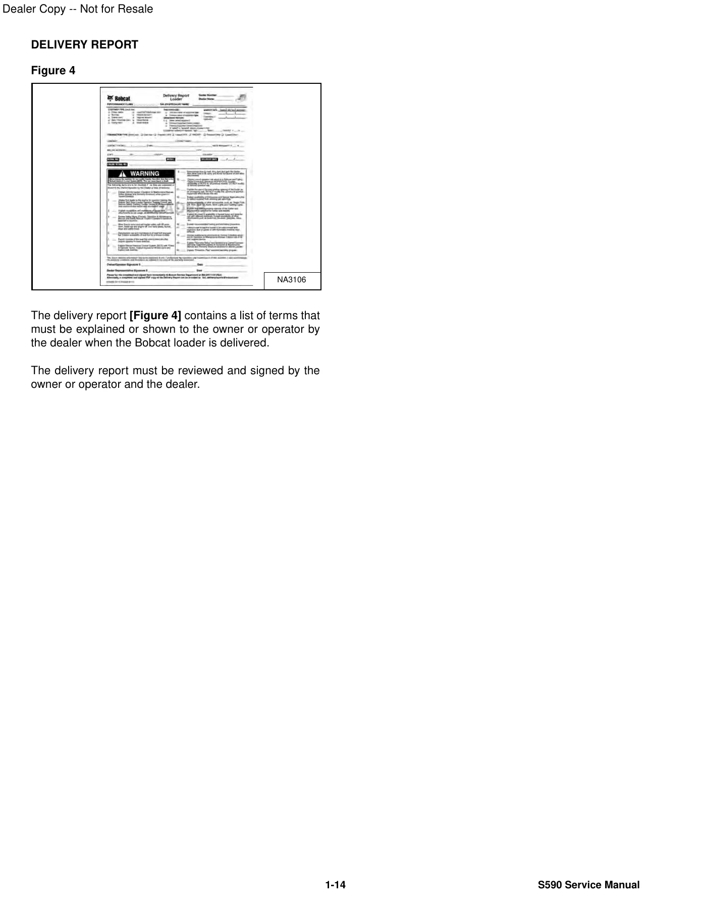
IMAGES PREVIEW
Hydraulic Diagnostics & Component Rebuilding
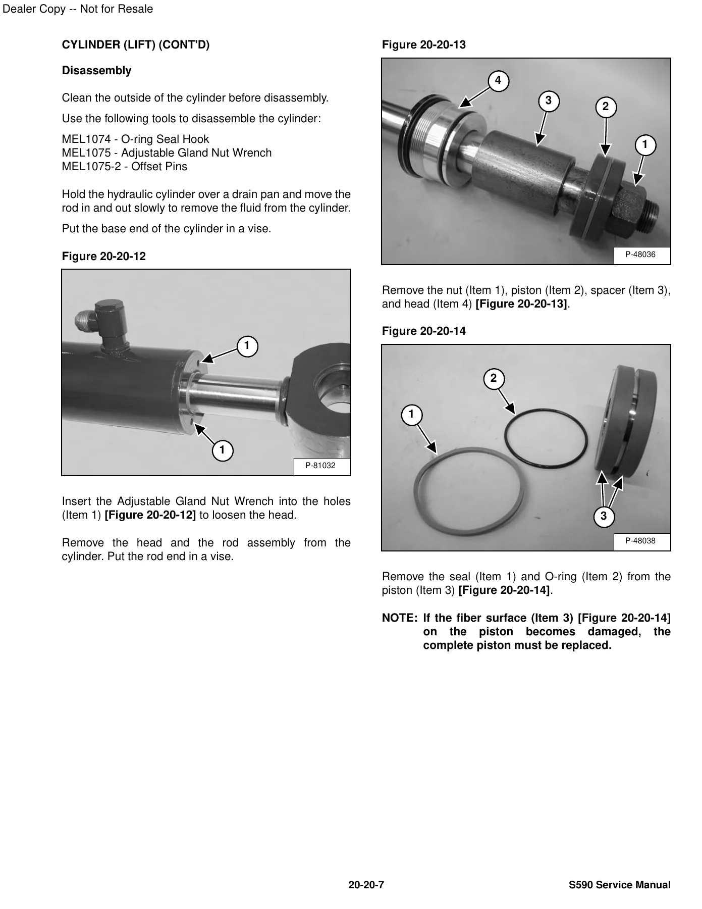
Hydraulic performance is vital on the Bobcat S590 Skid-Steer Loader, and this service manual provides deep technical instructions for isolating and correcting pressure loss or cycle-time faults. Step-by-step diagnostic workflows show how to isolate lift and tilt cylinders using pressure plugs to distinguish between internal piston seal blow-by and main spool leakage. Technicians are provided with complete tear-down and assembly specifications, such as torquing the lift cylinder piston retaining nut to 1152 N·m (850 ft-lb) or 780 N·m (575 ft-lb) on updated designs, tightening cylinder head glands to 373 N·m (275 ft-lb) or 550 N·m (405 ft-lb), and using specialized expander and compressor tools for seal installation without distortion.
Main system pressure calibration is clearly documented. Mechanics can verify primary relief valve cracking pressures at the front quick couplers using an in-line flow and pressure tester, adjusting the valve to factory specifications between 23787 and 24476 kPa (3450 to 3550 psi), or 24100 kPa (3500 psi) on B5N4 units. Accompanied by full hydraulic and hydrostatic schematics covering standard mechanical foot controls, advanced Selectable Joystick Controls (SJC), high-flow auxiliary circuits, and power attachment options, this manual serves as an indispensable shop guide.
Professional Shop Diagnostic Utility and Immediate Access
Utilizing the authentic Bobcat S590 Skid-Steer Loader Service Manual gives owner-operators, independent repair facilities, and equipment fleet managers the technical confidence to carry out repairs efficiently and accurately. Adhering to verified manufacturer assembly steps, bolt torque ratings, and system test parameters protects valuable machinery, prevents collateral hydraulic component failure, and ensures machine compliance with original factory performance benchmarks.
This service manual is delivered as an instant digital PDF download immediately upon completed order. You gain instant access with zero shipping wait times, allowing you to load the entire document onto shop laptops, field tablets, or mobile devices right at the machine. The PDF format allows you to navigate effortlessly through service chapters, zoom in on high-resolution hydraulic schematics, or print out clean mechanical procedure pages directly for bench work.
What Our Customers Say
🌟 Related Products
Discover more professional manuals for your equipment

Ammann ARR 1575 Trench Roller Workshop Service Manual (From Serial No. 5572567)

Kubota KX080-3 Excavator Workshop Service Manual PDF Download

New Holland F156.6 and F156.6A Motor Graders Workshop Service Manual


Reviews
There are no reviews yet.