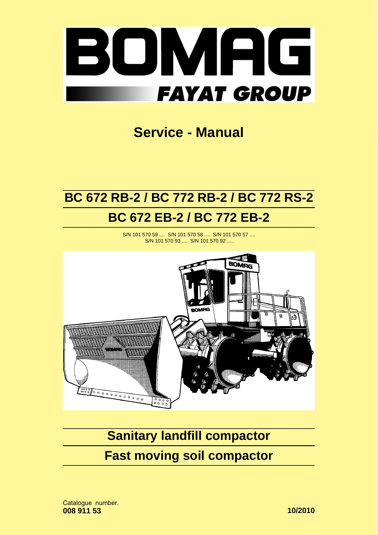
BOMAG BC 672 RB-2 BC 772 RB-2 RS-2 EB-2 Service Manual β Sanitary Landfill & Soil Compactor Repair Guide
$39.95 Original price was: $39.95.$23.95Current price is: $23.95.
Complete 1022-page BOMAG service manual for BC 672 RB-2, BC 772 RB-2, BC 772 RS-2, BC 672 EB-2 and BC 772 EB-2 compactors. Covers Deutz TCD 2015 engines, travel and working hydraulics, ESX/EMR electronics, diagnostics, wiring diagrams, maintenance and repair procedures.
Description
BOMAG BC 672 RB-2 / BC 772 RB-2 / BC 772 RS-2 / BC 672 EB-2 / BC 772 EB-2 Service Manual
This is the complete BOMAG service manual for the BC 672 RB-2, BC 772 RB-2, BC 772 RS-2, BC 672 EB-2 and BC 772 EB-2 sanitary landfill compactors and fast moving soil compactors. Document number 008 911 53. At over one thousand pages, it is the deep workshop reference for anyone maintaining, diagnosing or rebuilding these machines. It covers the Deutz TCD 2015 V06 diesel engine, hydrostatic travel system, working hydraulics, electrical and electronic control systems including EMR3 and ESX, air conditioning, central lubrication, and the oscillating articulated joint, with full wiring and hydraulic diagrams in the back.
File Details
- Manual type: Service / Repair Manual
- Brand: BOMAG
- Models covered: BC 672 RB-2, BC 772 RB-2, BC 772 RS-2, BC 672 EB-2, BC 772 EB-2
- Document number: 008 911 53
- Language: English
- Page count: 1022
- File format: PDF
- Serial number ranges shown on cover: S/N 101 570 59, 101 570 58, 101 570 57, 101 570 93, 101 570 92
Chapters Covered
- 1 General β Introduction, safety regulations, general repair instructions, tightening torques
- 2 Technical data β Dimensions, weights, travel characteristics, engine, compactor wheels, brake, steering, dozer blade, filling capacities, noise and vibration values
- 3 Maintenance β General notes, fuels and lubricants, maintenance table, running-in instructions
- 4 Electrics β Circuit diagrams, component designation, terminal designations, circuit symbols, batteries, fuse boxes, cab electrics, electronic control units, diagnostics concept
- 5 Engine electrics β Engine control unit EMR3, pin assignment, flashing codes, SERDIA and CAN-bus diagnostics, EMR3 fault code list, sensors (oil pressure, fuel temperature, charge air, coolant, crankshaft, camshaft), preheating system, generator, starter
- 6 Electronic control β ESX control functions, display module, fault codes, input codes, parameter setting, machine type setting
- 7 Trouble shooting β Machine drives in neutral, machine does not drive, travel power loss, steering faults, hydraulic oil overheating, central lubrication faults, travel system and working hydraulic troubleshooting charts
- 8 Installed components / connection overview β Component list, measuring and adjustment points on tandem travel pump, control valve block, connection overview
- 9 Air conditioning system β Physical basics, R134a refrigerant, compressor oil, monitoring devices, component descriptions, Climatronic control, evacuation, leak test, filling instructions, troubleshooting
- 10 Central lubrication system β System layout, technical description, control, lubrication process, progressive distributor, lubrication oil pump, fault-cause-remedy tables
- 11 Engine β Deutz TCD 2015 diesel engine description, lubrication oil circuit, coolant circuit, fuel circuit, injection system (MVS), exhaust gas recirculation, Wastegate charge pressure control, valve clearance, oil and filter changes, radiator and cooler cleaning, coolant change, fan V-belt, engine mounts, general troubleshooting chart
- 12 Working hydraulics β Hydraulic system, working hydraulics, steering and working pump, control valve block, load-sensing, steering and dozer blade control, individual component descriptions
- 13 Tests and adjustments in working hydraulics β Measuring and adjustment points on control valve block, tests and adjustments on steering/working pump
- 14 Travel hydraulics β Hydraulic system, travel system description, travel pump A4VG, travel motors A6VM, filtration, transfer box filter unit
- 15 Tests and adjustments in travel hydraulics β Measuring and adjustment points on tandem travel pump unit, pressure tests, high pressure relief and pressure override checks, charge pressure checks, DA-control valve adjustment, control chamber pressure, travel motor adjustment
- 16 Special tools, tests and adjustments β Special tools, test equipment and adjustment aids
- 17 Oscillating articulated joint β Removing and installing live ring, repairing the oscillating articulated joint, removing and installing steering cylinders
- 18 Suppliers documentation β Travel pump A4VG 71-180, steering/working pump A10VSO, travel motor A6VM 28-200, wheel drive GFT 110 R3, control valve block
- 19 Circuit diagrams β Hydraulic diagram 571 908 15, wiring diagrams 570 700 35, 570 700 37, 570 700 39, 570 700 42, 570 700 44
IMAGES PREVIEW
What This Manual Enables You to Do
With this BOMAG service manual on hand, a technician can carry out the full range of repair and maintenance tasks on the BC 672 RB-2, BC 772 RB-2, BC 772 RS-2, BC 672 EB-2 and BC 772 EB-2 compactors. The engine chapter walks through the Deutz TCD 2015 V06 β valve clearance adjustment, oil and filter changes, coolant circuit service, fuel system bleeding, MVS injection system, exhaust gas recirculation and turbocharger checks. The travel hydraulics chapters cover the A4VG variable pump and A6VM travel motors, including high pressure relief and pressure override settings, charge pressure tests, DA-control valve adjustment and displacement checks. The working hydraulics chapters handle the steering and dozer blade control valve block, load-sensing circuit, LS-pressure limitation and stand-by pressure adjustment. The electronics section covers the EMR3 engine control unit, ESX control, CAN-bus diagnostics and the full fault code lists, with flashing code tables and input codes for reading live data. Wiring and hydraulic diagrams at the end allow circuit tracing for any electrical or hydraulic fault. The air conditioning and central lubrication chapters round out the systems coverage with servicing, leak testing and fault tables.
Complete Bookmarks
The complete bookmarks in the βBOMAG BC 672 RB-2 BC 772 RB-2 RS-2 EB-2 Service Manual β Sanitary Landfill & Soil Compactor Repair Guideβ are as follows:
+BC 672 RB-2 / BC 772 RB-2 / BC 772 RS-2p. 1
+S/N 101 570 59 …. S/N 101 570 58 …. S/N 101 570 57 ….p. 1
+1 Generalp. 9
+1.1 Introductionp. 10
+This manual addresses the professionally qualified personnel or the after sales service of BOMAG, and should be of help and assistance in correct and efficient repair and maintenance work.p. 10
+Documentationp. 10
+1 Operating and maintenance instructionsp. 10
+These safety regulations must be read and applied by every person involved in the repair /maintenance of this machine. The applicable accident prevention instructions and the safety regulations in the operating and maintenance instructions must be ad…p. 10
+Generalp. 11
+Important notesp. 11
+These safety regulations must be read and applied by every person involved in the repair /maintenance of this machine. The applicable accident prevention instructions and the safety regulations in the operating and maintenance instructions must be ad…p. 11
+Paragraphs marked like this contain technical information for the optimal economical use of the machine.p. 11
+Paragraphs marked like this highlight possible dangers for machines or parts of the machine.p. 11
+Paragraphs marked like this highlight possible dangers for persons.p. 11
+Paragraphs marked like this point out practices for safe and environmental disposal of fuels and lubricants as well as replacement parts.p. 11
+Generalp. 11
+l For repair and maintenance work move the machine on a firm base and shut it down.p. 11
+Transport work with cranes and lifting tacklep. 11
+Cranes must only be operated by instructed persons who had been trained in handling cranes.p. 11
+l Follow the operating instructions of the manufacturer when working with cranes.p. 11
+l Follow the operating instructions of the operator when working with cranes.p. 11
+Precautions and codes of conduct for welding workp. 11
+Electric shock!p. 11
+l Check welding equipment and cables for damage before use (also the validity of inspection stickers).p. 11
+l In case of faults on the welding unit switch of the welding unit immediately and have it repaired by expert personnel.p. 12
+l Replace damaged insulating jaws and welding rod holders immediately.p. 12
+l Keep calm.p. 12
+Old oilsp. 12
+l Wear protective clothes and safety gloves, if possible.p. 12
+It is strictly prohibited to drain off oil into the soil, the sewer system or into natural waters. Old oil must be disposed of according to applicable environmental regulations. If in doubt you should consult your local authorities.p. 12
+Hydraulicsp. 12
+l Always relieve the pressure in the hydraulic system before disconnecting any lines. Hydraulic oil escaping under pressure can penetrate the skin and cause severe injury.p. 12
+It is strictly prohibited to drain off oil into the soil, the sewer system or into natural waters. Oil oil must be disposed of according to applicable environmental regulations. If in doubt you should consult your local authorities.p. 13
+Fuelsp. 13
+Repair work shall only performed by appropriately trained personnel or by the after sales service of BOMAG.p. 13
+l Fire extinguishers charged with FOAM, COp. 13
+Hot fuelsp. 13
+l Allow the fuel to cool down, to prevent any contact with a hot fluid.p. 13
+Synthetic rubberp. 13
+l If the material is in such a state it must only be touched with special protective gloves. The protective gloves must be disposed of according to applicable environmental regulations immediately after use.p. 13
+Poisonous substancesp. 13
+Enginep. 13
+Do not work on the fuel system while the engine is running. (Danger to life!)p. 13
+l Maintenance and cleaning work on the engine must only be performed with the engine stopped and cooled down. Make sure that the electric system is switched off and sufficiently secured against being switched on again (e.g. pull off ignition key, att…p. 13
+Air conditioning systemp. 14
+Work on air conditioning systems must only be carried out by persons who can provide sufficient evidence of their ability (proof of professionalism) and only with the appropriate technical equipment.p. 14
+l Always wear goggles and protective clothing when performing maintenance and repair work on air conditioning systems. Refrigerant withdraws heat from the environment when evaporating, which can cause injury by freezing when in contact with skin (boi…p. 14
+Handling pressure vesselsp. 14
+l Since the fluid container is pressurized, the manufacture and testing of these pressure vessels is governed by the pressure vessel directive. The pressure vessels must be repetitively tested by an expert as specified in TRB 532 Inspection by Expert…p. 14
+It is strictly prohibited to release refrigerant into the atmosphere during operation, maintenance and repair work and when taking air conditioning systems into or out of service.p. 14
+Batteryp. 14
+l Always wear goggles and protective clothing to service or clean batteries! Battery acid can cause severe injury by cauterization when coming in contact with skin.p. 14
+Special safety regulationsp. 15
+l Use only genuine BOMAG spare parts for repair and maintenance work. Genuine spare parts and original accessories were specially developed, tested and approved for the machine.p. 15
+The values specified in the table apply for screws:p. 16
+Generalp. 16
+l Before removing or disassembling parts, assemblies, components or hoses mark these parts for easier assembly.p. 16
+The values specified in the table apply for screws:p. 16
+Generalp. 16
+l In approx. 10 % of the examined cases the problems were caused by control units.p. 16
+l Before changing any expensive components, such as control units, you should run a systematic trouble shooting session to eliminate any other possible fault sources. Knowledge in basic electrics is required for this purpose. If a fault was diagnosed…p. 16
+Electrics and weldingp. 17
+Before starting welding work you should disconnect the negative battery pole or interrupt the electric circuit with the main battery switch, disconnect the generator and pull the plugs off all control units in order to protect the electrical system o…p. 17
+l Disconnect the minus pole of the battery or interrupt the electric circuit with the main battery switch.p. 17
+The values specified in the table apply for screws:p. 17
+The values specified in the table apply for screws:p. 18
+The values specified in the table apply for screws:p. 19
+Repair work on hydraulic elements shall only performed by appropriately trained personnel or by the after sales service of BOMAG.p. 19
+Please notep. 19
+Cleanliness is of utmost importance. Dirt and other contaminations must strictly be kept out of the system.p. 19
+l Connections and screw fittings, filler neck covers and their immediate surrounding areas must be cleaned before removal.p. 19
+Before commissioningp. 19
+l Fill the housings of hydraulic pumps and motors with hydraulic oil. Use only hydraulic oils according to the specification in the maintenance instructions.p. 19
+Taking into operationp. 19
+l Bleed the hydraulic circuits.p. 19
+After taking into operationp. 19
+l Check fittings and flanges for leaks.p. 19
+The values specified in the table apply for screws:p. 20
+Chemicals/ozone layer regulationp. 20
+l have proven to have sufficient expert knowledge,p. 20
+Cleanliness is of utmost importance. Dirt and other contaminations must strictly be kept out of the system.p. 20
+l Tools used on refrigeration circuits must be of excellent condition, thus to avoid the damage of any connections.p. 20
+The values specified in the table apply for screws:p. 21
+l Spare parts should be left in their original packaging as long as possible and should only be unpacked just before use.p. 21
+l When parts are unpacked any connections must be closed with suitable plugs or caps, in order to preventp. 21
+Notes and measures to be applied before starting work in the fuel systemp. 21
+l The fuel system must be closed. Visual examination for leaks / damage in the fuel system.p. 21
+Notes and measures to be applied during work in the fuel systemp. 22
+l Wear clean working clothes.p. 22
+Notes and measures concerning the workshop areap. 22
+l For work, such as disassembly and assembly of defective hydraulic components in the Common Rail System, it is strongly recommended to set up a separate workshop area, i.e. an area which is spatially separated from all other areas (general vehicle r…p. 22
+Notes and measures for work place and tools in the workshopp. 22
+l A special work place must be set up for work on disassembled components.p. 22
+The values specified in the table apply for screws:p. 23
+All fuel hoses have two layers of material, a reinforced rubber coating outside and an internal Viton hose. If a fuel hose has come loose one must make absolutely sure that the internal Viton layer has not been separated from the reinforced outer lay…p. 23
+The values specified in the table apply for screws:p. 24
+l Before assembling a new seal or gasket make sure that the sealing surface is free of pitting, flutes, corrosion or other damage.p. 24
+l Lubricate the sealing lips (2)p. 24
+If possible, use an assembly sleeve (1p. 24
+l Lubricate the outer rim (arrow 3p. 24
+l Press or knock the seal into the housing, until it is flush with the housing surface.p. 24
+If possible, use a "bell" (1p. 24
+The values specified in the table apply for screws:p. 25
+Feather keys may only be reused if they are free of damage.p. 25
+l Clean and thoroughly examine the feather key.p. 25
+The values specified in the table apply for screws:p. 25
+Ball and roller bearings may only be reused if they are free of damage and do not show any signs of wear.p. 25
+l If a ball or roller bearing of a bearing pair shows defects, both ball or roller bearings need to be replaced.p. 25
+When assembling the ball or roller bearing to the shaft load must only be applied to the inner race 1p. 26
+The values specified in the table apply for screws:p. 26
+Tighten nuts or screws with the tightening torques specified in the following tables of tightening torques. Tightening torques deviating from the ones in the table are specially mentioned in the repair instructions.p. 26
+l Nut of a higher strength can generally be used instead of nuts of a lower strength classification.p. 26
+l Before tightening you should lightly oil the thread, in order to ensure low friction movement.p. 26
+The first number corresponds with 1/100 of the nominal tensile strength (minimum tensile strength) in N/ mmp. 27
+l The nominal tensile strength is 12 X 100 N/mmp. 27
+When exceeding the lower yield point, the material will return to its original shape when being relieved (plastic deformation).p. 27
+l The lower tensile strength is 9/10 X 1200 N/mmp. 27
+However, these values are by no means identical with the tightening torques, which are to be set on a torque wrench. The corresponding calculation requires a higher effort and, in the end, depends on the materials to be bolted together.p. 27
+In a connection with a screw, these nuts 1p. 27
+Strength class of nutp. 27
+Strength class of associated screwp. 27
+4p. 27
+3.6, 4.6, 4.8p. 27
+5p. 27
+3.6, 4.6, 4.8p. 27
+6p. 27
+6.8p. 27
+8p. 27
+8.8p. 27
+9p. 27
+9.8p. 27
+10p. 27
+10.8p. 27
+12p. 27
+12.8p. 27
+The preceding "0" indicates that, due to their low height, nuts 2p. 27
+This standard contains strength classes (hardness classes) for nuts 3p. 27
+For small nutsp. 28
+l The 12 o'clock position is identified by a dot or the manufacturer's symbol.p. 28
+The screw head is marked with a stamped in, round cavity 3p. 28
+The values specified in the table apply for screws:p. 30
+l black oiledp. 30
+DACROMET is a surface protection that mainly consists of zinc and aluminium in a chromium oxide matrix. DACROMETIZATION provides excellent corrosion protection for metal surfaces by applying a mineral coating with metallic-silver appearance.p. 30
+Tightening torques for screws with metric unified threadp. 30
+Coefficient of friction m tot. = 0,14p. 30
+Screw dimensionp. 30
+Tightening torques Nmp. 30
+8.8p. 30
+10.9p. 30
+12.9p. 30
+M4p. 30
+3p. 30
+5p. 30
+5p. 30
+M5p. 30
+6p. 30
+9p. 30
+10p. 30
+M6p. 30
+10p. 30
+15p. 30
+18p. 30
+M8p. 30
+25p. 30
+35p. 30
+45p. 30
+M10p. 30
+50p. 30
+75p. 30
+83p. 30
+M12p. 30
+88p. 30
+123p. 30
+147p. 30
+M14p. 30
+137p. 30
+196p. 30
+235p. 30
+M16p. 30
+211p. 30
+300p. 30
+358p. 30
+M18p. 30
+290p. 30
+412p. 30
+490p. 30
+M20p. 30
+412p. 30
+578p. 30
+696p. 30
+M22p. 30
+560p. 30
+785p. 30
+942p. 30
+M24p. 30
+711p. 30
+1000p. 30
+1200p. 30
+M27p. 30
+1050p. 30
+1480p. 30
+1774p. 30
+M30p. 30
+1420p. 30
+2010p. 30
+2400p. 30
+Tightening torques for screws with metric unified fine threadp. 30
+Coefficient of friction m tot. = 0,14p. 30
+Screw dimensionp. 30
+Tightening torques Nmp. 30
+8.8p. 30
+10.9p. 30
+12.9p. 30
+M8 x 1p. 30
+26p. 30
+37p. 30
+48p. 30
+M10 x 1.25p. 30
+52p. 30
+76p. 30
+88p. 30
+M12 x 1,25p. 30
+98p. 30
+137p. 30
+126p. 30
+M12 x 1.5p. 30
+93p. 30
+127p. 30
+152p. 30
+M14 x 1.5p. 30
+152p. 30
+216p. 30
+255p. 30
+M16 x 1.5p. 30
+225p. 30
+318p. 30
+383p. 30
+M18 x 1.5p. 30
+324p. 30
+466p. 30
+554p. 30
+M20 x 1.5p. 30
+461p. 30
+628p. 30
+775p. 30
+M22 x 1.5p. 30
+618p. 30
+863p. 30
+1058p. 30
+M24 x 2p. 30
+780p. 30
+1098p. 30
+1294p. 30
+M27 x2p. 30
+1147p. 30
+1578p. 30
+1920p. 30
+M30 x 2p. 30
+1568p. 30
+2254p. 30
+2695p. 30
+Tightening torques for screws treated with anti-seizure paste OKS 240 (copper paste)p. 31
+Tightening torques for screws treated with anti-seizure paste OKS 240p. 31
+Screw dimensionp. 31
+Tightening torques Nmp. 31
+8.8p. 31
+10.9p. 31
+12.9p. 31
+M16p. 31
+169p. 31
+240p. 31
+287p. 31
+M16 x 1.5p. 31
+180p. 31
+255p. 31
+307p. 31
+M18p. 31
+232p. 31
+330p. 31
+392p. 31
+M18 x 1.5p. 31
+260p. 31
+373p. 31
+444p. 31
+M20p. 31
+330p. 31
+463p. 31
+557p. 31
+M20 x 1.5p. 31
+369p. 31
+502p. 31
+620p. 31
+M22p. 31
+448p. 31
+628p. 31
+754p. 31
+M22 x 1.5p. 31
+495p. 31
+691p. 31
+847p. 31
+M24p. 31
+569p. 31
+800p. 31
+960p. 31
+M24 x 2p. 31
+624p. 31
+879p. 31
+1036p. 31
+M27p. 31
+840p. 31
+1184p. 31
+1520p. 31
+M27 X 2p. 31
+918p. 31
+1263p. 31
+1536p. 31
+M30p. 31
+1136p. 31
+1608p. 31
+1920p. 31
+M30 x 2p. 31
+1255p. 31
+1804p. 31
+2156p. 31
+3/4β – 10 UNCp. 31
+276p. 31
+388p. 31
+464p. 31
+3/4β – 16 UNCp. 31
+308p. 31
+432p. 31
+520p. 31
+Tightening torques for wheel nuts (fine thread)p. 31
+Coefficient of friction m tot. = 0,14p. 31
+Thread diameterp. 31
+Tightening torques Nmp. 31
+10.9p. 31
+M12x1.5p. 31
+100p. 31
+M14x1.5p. 31
+150p. 31
+M18x1.5p. 31
+300 – 350p. 31
+M20x1.5p. 31
+400 – 500p. 31
+M22x1.5p. 31
+500 – 600p. 31
+l black oiledp. 32
+The difference between Withworth and UNF/UNC threads is the fact that UNF and UNC threads have 60Β° flanks, as the metric ISO-thread, whereas Withworth has a flank of only 55Β°.p. 32
+Tightening torques for screws with UNC thread, UNC Unified Coarse Thread Series, American Unified Coarse Threadp. 32
+Tightening torques for screws with UNC thread,p. 32
+Coefficient of friction m tot. = 0,14p. 32
+Screw dimensionp. 32
+Tightening torques Nmp. 32
+8.8p. 32
+10.9p. 32
+12.9p. 32
+1/4β – 20p. 32
+11p. 32
+15p. 32
+19p. 32
+5/16β – 18p. 32
+23p. 32
+32p. 32
+39p. 32
+3/8β – 16p. 32
+39p. 32
+55p. 32
+66p. 32
+7/16β – 14p. 32
+62p. 32
+87p. 32
+105p. 32
+1/2β – 13p. 32
+96p. 32
+135p. 32
+160p. 32
+9/16β – 12p. 32
+140p. 32
+200p. 32
+235p. 32
+5/8β – 11p. 32
+195p. 32
+275p. 32
+330p. 32
+3/4β – 10p. 32
+345p. 32
+485p. 32
+580p. 32
+7/8β – 9p. 32
+560p. 32
+770p. 32
+940p. 32
+1β – 8p. 32
+850p. 32
+1200p. 32
+1450p. 32
+1 1/8β – 7p. 32
+1200p. 32
+1700p. 32
+2000p. 32
+1 1/4β – 7p. 32
+1700p. 32
+2400p. 32
+2900p. 32
+1 3/8β – 6p. 32
+2200p. 32
+3100p. 32
+3700p. 32
+1 1/2β – 6p. 32
+3000p. 32
+4200p. 32
+5100p. 32
+Tightening torques for screws with UNF thread, UNF Unified National Fine Thread Series, American Unified Fine Threadp. 32
+Tightening torques for screws with UNF thread,p. 32
+Coefficient of friction m tot. = 0,14p. 33
+Screw dimensionp. 32
+Tightening torques Nmp. 32
+8.8p. 32
+10.9p. 32
+12.9p. 32
+1/4β – 28p. 32
+13p. 32
+18p. 32
+22p. 32
+5/16β – 24p. 32
+25p. 32
+35p. 32
+42p. 32
+3/8β – 24p. 32
+45p. 32
+63p. 32
+76p. 32
+7/16β – 20p. 32
+70p. 32
+100p. 32
+120p. 32
+1/2β – 20p. 32
+110p. 32
+155p. 32
+185p. 32
+9/16β – 18p. 32
+155p. 32
+220p. 32
+260p. 32
+5/8β – 18p. 32
+220p. 32
+310p. 32
+370p. 32
+3/4β – 16p. 32
+385p. 32
+540p. 32
+650p. 32
+7/8β -14p. 32
+620p. 32
+870p. 32
+1050p. 32
+1β – 12p. 33
+930p. 33
+1300p. 33
+1600p. 33
+1 1/8β – 12p. 33
+1350p. 33
+1900p. 33
+2300p. 33
+1 1/4β – 12p. 33
+1900p. 33
+2700p. 33
+3200p. 33
+1 3/8β – 12p. 33
+2600p. 33
+3700p. 33
+4400p. 33
+1 1/2β – 12p. 33
+3300p. 33
+4600p. 33
+5600p. 33
+2 Technical datap. 35
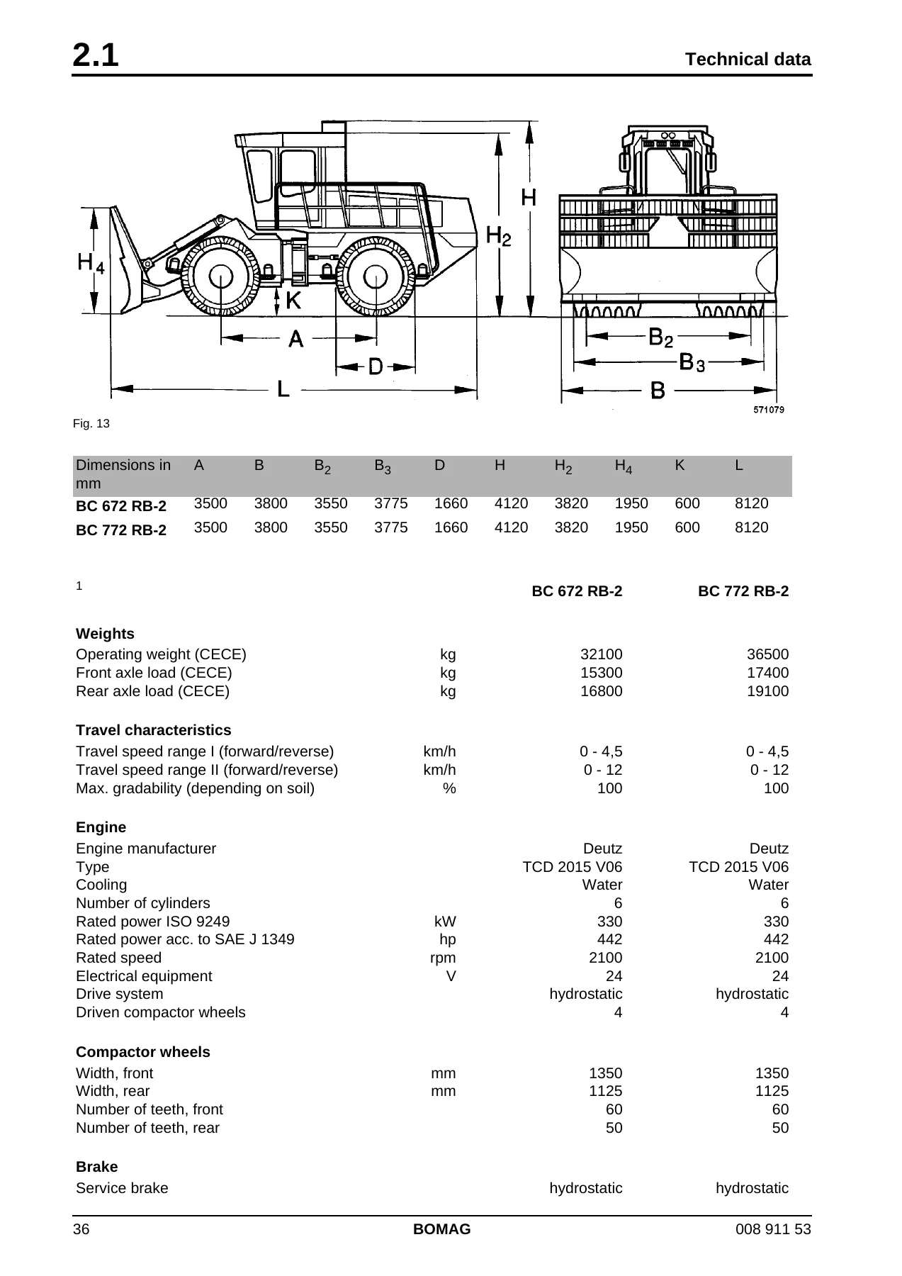
+Dimensions in mmp. 36
+Ap. 36
+Bp. 36
+B2p. 36
+Bp. 36
+B3p. 36
+Bp. 36
+Dp. 36
+Hp. 36
+H2p. 36
+Hp. 36
+H4p. 36
+Hp. 36
+Kp. 36
+Lp. 36
+BC 672 RB-2p. 36
+3500p. 36
+3800p. 36
+3550p. 36
+3775p. 36
+1660p. 36
+4120p. 36
+3820p. 36
+1950p. 36
+600p. 36
+8120p. 36
+BC 772 RB-2p. 36
+3500p. 36
+3800p. 36
+3550p. 36
+3775p. 36
+1660p. 36
+4120p. 36
+3820p. 36
+1950p. 36
+600p. 36
+8120p. 36
+Subject to technical alterations.p. 36
+BC 672 RB-2p. 36
+BC 772 RB-2p. 36
+Weightsp. 36
+Operating weight (CECE)p. 36
+kgp. 36
+32100p. 36
+36500p. 36
+Front axle load (CECE)p. 36
+kgp. 36
+15300p. 36
+17400p. 36
+Rear axle load (CECE)p. 36
+kgp. 36
+16800p. 36
+19100p. 36
+Travel characteristicsp. 36
+Travel speed range I (forward/reverse)p. 36
+km/hp. 36
+0 – 4,5p. 36
+0 – 4,5p. 36
+Travel speed range II (forward/reverse)p. 36
+km/hp. 36
+0 – 12p. 36
+0 – 12p. 36
+Max. gradability (depending on soil)p. 36
+%p. 36
+100p. 36
+100p. 36
+Enginep. 36
+Engine manufacturerp. 36
+Deutzp. 36
+Deutzp. 36
+Typep. 36
+TCD 2015 V06p. 36
+TCD 2015 V06p. 36
+Coolingp. 36
+Waterp. 36
+Waterp. 36
+Number of cylindersp. 36
+6p. 36
+6p. 36
+Rated power ISO 9249p. 36
+kWp. 36
+330p. 36
+330p. 36
+Rated power acc. to SAE J 1349p. 36
+hpp. 36
+442p. 36
+442p. 36
+Rated speedp. 36
+rpmp. 36
+2100p. 36
+2100p. 36
+Electrical equipmentp. 36
+Vp. 36
+24p. 36
+24p. 36
+Drive systemp. 36
+hydrostaticp. 36
+hydrostaticp. 36
+Driven compactor wheelsp. 36
+4p. 36
+4p. 36
+Compactor wheelsp. 36
+Width, frontp. 36
+mmp. 36
+1350p. 36
+1350p. 36
+Width, rearp. 36
+mmp. 36
+1125p. 36
+1125p. 36
+Number of teeth, frontp. 36
+60p. 36
+60p. 36
+Number of teeth, rearp. 36
+50p. 36
+50p. 36
+Brakep. 36
+Service brakep. 36
+hydrostaticp. 36
+hydrostaticp. 36
+Parking brakep. 37
+mechanicalp. 37
+mechanicalp. 37
+Emergency brakep. 37
+hydro-mechanicalp. 37
+Steeringp. 37
+Type of steeringp. 37
+Oscill.-articul.p. 37
+Steering operationp. 37
+hydraulicp. 37
+hydraulicp. 37
+Steering anglep. 37
+Β± Β°p. 37
+40p. 37
+40p. 37
+Oscillation anglep. 37
+Β± Β°p. 37
+15p. 37
+15p. 37
+Inner track radiusp. 37
+mmp. 37
+3090p. 37
+3090p. 37
+Dozer bladep. 37
+Height adjustment above ground levelp. 37
+mmp. 37
+1200p. 37
+1200p. 37
+Height adjustment below ground levelp. 37
+mmp. 37
+120p. 37
+120p. 37
+Filling capacitiesp. 37
+Fuel (diesel)p. 37
+lp. 37
+500p. 37
+500p. 37
+Engine oilp. 37
+lp. 37
+36p. 37
+36p. 37
+Coolantp. 37
+lp. 37
+approx. 50p. 37
+approx. 50p. 37
+Hydraulic oilp. 37
+lp. 37
+350p. 37
+350p. 37
+Dimensions in mmp. 38
+Ap. 38
+Bp. 38
+B2p. 38
+Bp. 38
+B3p. 38
+Bp. 38
+Dp. 38
+Hp. 38
+H2p. 38
+Hp. 38
+H4p. 38
+Hp. 38
+Kp. 38
+Lp. 38
+BC 772 RS-2p. 38
+3875p. 38
+3800p. 38
+3550p. 38
+3775p. 38
+1660p. 38
+4120p. 38
+3820p. 38
+1800p. 38
+600p. 38
+9275p. 38
+Subject to technical alterations.p. 38
+BC 772 RS-2p. 38
+Weightsp. 38
+Operating weight (CECE)p. 38
+kgp. 38
+37300p. 38
+Front axle load (CECE)p. 38
+kgp. 38
+20800p. 38
+Rear axle load (CECE)p. 38
+kgp. 38
+16500p. 38
+Travel characteristicsp. 38
+Travel speed range I (forward/reverse)p. 38
+km/hp. 38
+0 – 4,5p. 38
+Travel speed range II (forward/reverse)p. 38
+km/hp. 38
+0 – 12p. 38
+Max. gradability (depending on soil)p. 38
+%p. 38
+75p. 38
+Drivep. 38
+Engine manufacturerp. 38
+Deutzp. 38
+Typep. 38
+TCD 2015 V06p. 38
+Coolingp. 38
+Waterp. 38
+Number of cylindersp. 38
+6p. 38
+Rated power ISO 9249p. 38
+kWp. 38
+330p. 38
+Rated power acc. to SAE J 1349p. 38
+hpp. 38
+442p. 38
+Rated speedp. 38
+rpmp. 38
+2100p. 38
+Electrical equipmentp. 38
+Vp. 38
+24p. 38
+Drive systemp. 38
+hydrostaticp. 38
+Driven compactor wheelsp. 38
+4p. 38
+Compactor wheelsp. 38
+Width, frontp. 38
+mmp. 38
+1350p. 38
+Width, rearp. 38
+mmp. 38
+1125p. 38
+Number of teeth, frontp. 38
+60p. 38
+Number of teeth, rearp. 38
+50p. 38
+Brakep. 39
+Service brakep. 39
+hydrostaticp. 39
+Parking brakep. 39
+mechanicalp. 39
+Emergency brakep. 39
+hydro-mechanicalp. 39
+Steeringp. 39
+Type of steeringp. 39
+Oscill.-articul.p. 39
+Steering operationp. 39
+hydraulicp. 39
+Steering anglep. 39
+Β± Β°p. 39
+30p. 39
+Oscillation anglep. 39
+Β± Β°p. 39
+15p. 39
+Inner track radiusp. 39
+mmp. 39
+3750p. 39
+Dozer bladep. 39
+Height adjustment above ground levelp. 39
+mmp. 39
+5350p. 39
+Height adjustment below ground levelp. 39
+mmp. 39
+50p. 39
+Filling capacitiesp. 39
+Fuel (diesel)p. 39
+lp. 39
+750p. 39
+Engine oilp. 39
+lp. 39
+36p. 39
+Hydraulic oilp. 39
+lp. 39
+350p. 39
+Coolantp. 39
+lp. 39
+approx. 50p. 39
+Dimensions in mmp. 40
+Ap. 40
+Bp. 40
+B2p. 40
+Bp. 40
+B3p. 40
+Bp. 40
+Dp. 40
+Hp. 40
+H2p. 40
+Hp. 40
+H4p. 40
+Hp. 40
+Kp. 40
+Lp. 40
+BC 672 EB-2p. 40
+3500p. 40
+3800p. 40
+3550p. 40
+3425p. 40
+1580p. 40
+4120p. 40
+3820p. 40
+1050p. 40
+600p. 40
+8120p. 40
+BC 772 EB-2p. 40
+3500p. 40
+3800p. 40
+3550p. 40
+3775p. 40
+1580p. 40
+4120p. 40
+3820p. 40
+1050p. 40
+600p. 40
+8120p. 40
+Subject to technical alterations, technical data may deviate for optional equipmentp. 40
+BC 672 EB-2p. 40
+BC 772 EB-2p. 40
+Weightsp. 40
+Operating weight (CECE)p. 40
+kgp. 40
+28900p. 40
+35300p. 40
+Front axle load (CECE)p. 40
+kgp. 40
+14100p. 40
+17300p. 40
+Rear axle load (CECE)p. 40
+kgp. 40
+14800p. 40
+18000p. 40
+Travel characteristicsp. 40
+Travel speed range I (forward/reverse)p. 40
+km/hp. 40
+0 – 4,5p. 40
+0 – 4,5p. 40
+Travel speed range II (forward/reverse)p. 40
+km/hp. 40
+0 – 12p. 40
+0 – 12p. 40
+Max. gradability (depending on soil)p. 40
+%p. 40
+100p. 40
+100p. 40
+Enginep. 40
+Engine manufacturerp. 40
+Deutzp. 40
+Deutzp. 40
+Typep. 40
+TCD 2015 V06p. 40
+TCD 2015 V06p. 40
+Coolingp. 40
+Waterp. 40
+Waterp. 40
+Number of cylindersp. 40
+6p. 40
+6p. 40
+Rated power ISO 9249p. 40
+kWp. 40
+330p. 40
+330p. 40
+Rated power acc. to SAE J 1349p. 40
+hpp. 40
+442p. 40
+442p. 40
+Rated speedp. 40
+rpmp. 40
+2100p. 40
+2100p. 40
+Electrical equipmentp. 40
+Vp. 40
+24p. 40
+24p. 40
+Drive systemp. 40
+hydrostaticp. 40
+hydrostaticp. 40
+Driven compactor wheelsp. 40
+4p. 40
+4p. 40
+Compactor wheelsp. 40
+Width, frontp. 40
+mmp. 40
+1175p. 40
+1350p. 40
+Width, rearp. 40
+mmp. 40
+1125p. 40
+1125p. 40
+Number of teeth, frontp. 40
+50p. 40
+60p. 40
+Number of teeth, rearp. 40
+50p. 40
+50p. 40
+Brakep. 40
+Service brakep. 41
+hydrostaticp. 41
+hydrostaticp. 41
+Parking brakep. 41
+mechanicalp. 41
+mechanicalp. 41
+Emergency brakep. 41
+hydro-mechanicalp. 41
+Steeringp. 41
+Type of steeringp. 41
+Oscill.-articul.p. 41
+Steering operationp. 41
+hydraulicp. 41
+hydraulicp. 41
+Steering anglep. 41
+Β± Β°p. 41
+40p. 41
+40p. 41
+Oscillation anglep. 41
+Β± Β°p. 41
+15p. 41
+15p. 41
+Inner track radiusp. 41
+mmp. 41
+3265p. 41
+3090p. 41
+Dozer bladep. 41
+Height adjustment above ground levelp. 41
+mmp. 41
+1200p. 41
+1200p. 41
+Height adjustment below ground levelp. 41
+mmp. 41
+120p. 41
+120p. 41
+Filling capacitiesp. 41
+Fuel (diesel)p. 41
+lp. 41
+500p. 41
+500p. 41
+Engine oilp. 41
+lp. 41
+36p. 41
+36p. 41
+Coolantp. 41
+lp. 41
+approx. 50p. 41
+approx. 50p. 41
+Hydraulic oilp. 41
+lp. 41
+350p. 41
+350p. 41
+Additional engine datap. 42
+Combustion principlep. 42
+4-stroke dieselp. 42
+Low idle speedp. 42
+rpmp. 42
+800 – 850p. 42
+High idle speedp. 42
+rpmp. 42
+2100 – 2160p. 42
+Specific fuel consumptionp. 42
+g/kWhp. 42
+225p. 42
+Valve clearance intakep. 42
+mmp. 42
+0,25p. 42
+Valve clearance exhaustp. 42
+mmp. 42
+0,3p. 42
+Injection valves opening pressurep. 42
+barp. 42
+Pump/nozzlep. 42
+Starter powerp. 42
+kWp. 42
+6,6p. 42
+Transfer boxp. 42
+Reduction ratio of travel pump drivep. 42
+1,12p. 42
+Reduction ratio of working pump drivep. 42
+1,12p. 42
+Pressure setting PRV coolant circuit (high idle)p. 42
+barp. 42
+25p. 42
+Travel pumpp. 42
+Manufacturerp. 42
+Bosch-Rexrothp. 42
+Type frontp. 42
+A4 VG 71 DAp. 42
+Type rearp. 42
+A4 VG 71 DGp. 42
+Systemp. 42
+Axial piston/swash platep. 42
+Max. displacementp. 42
+cm3/rev.p. 42
+cmp. 42
+71p. 42
+Max. flow capacityp. 42
+l/minp. 42
+156,2p. 42
+High pressure limitationp. 42
+barp. 42
+480 – 20p. 42
+Pressure override valvep. 42
+barp. 42
+420 Β± 10p. 42
+Charge pressure, high idlep. 42
+barp. 42
+30 Β± 2p. 42
+Pilot pressure control start at engine speedp. 42
+6 bar at 1025 rpmp. 42
+_Absolute pressure at control startp. 42
+50 bar at 1025 rpmp. 42
+__Corresponds with pump speedp. 42
+rpmp. 42
+1150 Β± 50p. 42
+Pilot pressure at control endp. 42
+14 bar at 1700 rpmp. 42
+_Absolute pressure at control endp. 42
+400 bar at 1700 rpmp. 42
+Travel motorsp. 42
+Manufacturerp. 42
+Bosch-Rexrothp. 42
+Typep. 42
+A6VM 160 HA 2Tp. 42
+Quantityp. 42
+4p. 42
+Systemp. 42
+Axial piston β bent axlep. 42
+Displacement (stage 1)p. 42
+cm3/rev.p. 42
+cmp. 42
+160p. 42
+Displacement (stage 2)p. 42
+cm3/rev.p. 42
+cmp. 42
+50p. 42
+Control start change-overp. 42
+barp. 42
+280 Β± 5p. 42
+Control end change-overp. 42
+barp. 42
+380 Β± 10p. 42
+Perm. leak oil ratep. 42
+l/minp. 42
+7p. 42
+Wheel drivep. 42
+Manufacturerp. 42
+Bosch-Rexrothp. 42
+Typep. 42
+GFT 110 R3p. 42
+Reduction ratiop. 42
+83p. 42
+Wheel drivep. 42
+from serial numberp. 42
+101 570 591 019 BC 672 RB-2p. 42
+Manufacturerp. 42
+Bonfigliolip. 42
+Typep. 42
+716 C 3Bp. 42
+Steering/working pumpp. 42
+Typep. 43
+A10VO 71 DFRp. 43
+Systemp. 43
+Axial piston/swash platep. 43
+Max. displacementp. 43
+cm3/rev.p. 43
+cmp. 43
+71p. 43
+Max. dozer plate pressurep. 43
+barp. 43
+230 + 10p. 43
+Max. steering pressurep. 43
+barp. 43
+200 + 10p. 43
+Stand-by pressurep. 43
+barp. 43
+30 Β± 2p. 43
+Valve block, working hydraulicsp. 43
+Typep. 43
+2M6-22p. 43
+Max. steering pressurep. 43
+barp. 43
+230 + 10p. 43
+Max. dozer plate pressurep. 43
+barp. 43
+230 + 10p. 43
+LS-pressure limitationp. 43
+barp. 43
+210 + 10p. 43
+Tank pre-loading valvep. 43
+barp. 43
+18p. 43
+Charge circuit filterp. 43
+micronp. 43
+12p. 43
+Return flow filterp. 43
+micronp. 43
+80p. 43
+Noise valuep. 44
+Lp. 44
+Lp. 44
+Lp. 44
+These sound values were determined according to ISO 3744 for the sound capacity level (Lp. 44
+Vibration valuep. 44
+The weighted effective acceleration value determined according to ISO 7096 isp. 44
+The weighted effective acceleration value determined according to EN 500/ISO isp. 44
+3 Maintenancep. 45
+3.1 General notes on maintenancep. 46
+When performing maintenance work always comply with the appropriate safety regulations.p. 46
+l Always clean machine and engine thoroughly before starting maintenance work.p. 46
+During maintenance work catch all oils and fuels and do not let them seep into the ground or into the sewage system. Dispose of oils and fuels environmentally.p. 46
+Notes on the fuel systemp. 46
+l Keep fuel free of contaminants and water, since this will damage the injection elements of the engine.p. 46
+Notes on the performance of the enginep. 46
+Notes on the cooling systemp. 46
+Notes on the hydraulic systemp. 46
+l If, during the daily inspection of the oil level the hydraulic oil level is found to have dropped, check all lines, hoses and components for leaks.p. 46
+Welding work on the refuse compactorp. 46
+l Disconnect the main battery switchp. 46
+l Pull the plugs off all control units, engine control unit (EMR), travel control (ESX) and additional control (DIOS).p. 46
+3.2 Fuels and lubricantsp. 47
+Engine oilp. 47
+www.deutz.comp. 47
+dep. 47
+>>SERVICE >> Fuels and lubricants and diagnostics >> DeutzQualityClass >> DQC-Release listp. 47
+enp. 47
+>>SERVICE >> Fuels and lubricants and diagnostics >> DeutzQualityClass >>DQC- release listp. 47
+l Use winter grade engine oil for winter operation!p. 47
+Optimal operating conditions can be achieved by using the oil viscosity chartp. 47
+DQC III, DQC IVp. 47
+When using fuels with a sulphur content of more than 0,5% to 1% or under permanent ambient temperatures below -10Β°C and when using biodegradable diesel fuel the oil change intervals must be halved.p. 47
+Fuelsp. 47
+l EN 590p. 48
+Coolantp. 48
+Fresh water analysis valuesp. 48
+pH-value at 20 Β°Cp. 48
+6.5 – 8.5p. 48
+Chloride ion content (mg/l) (ppm)p. 48
+max. 100p. 48
+Sulphate ion content (mg/l) (ppm)p. 48
+max. 100p. 48
+Total hardness [Β°dGH]p. 48
+3 – 12p. 48
+corresponds with a potash ion content (mmol/l) ofp. 48
+0.54 – 3.56p. 48
+Carbon hardness proportion of the total hardness (Β°d)p. 48
+min. 3p. 48
+corresponds with a content of CaCO3 (mg/l) (ppm)p. 48
+corresponds with a content of CaCOp. 48
+min. 53.4p. 48
+l pH-value too low Adding of caustic lye of soda or caustic potash solution.p. 48
+Another analysis must be made after the fresh water has been prepared.p. 48
+Do not mix different coolants and additives of any other kind.p. 48
+Mixing ratiop. 49
+Cooling system protection agentp. 49
+Fresh waterp. 49
+Cold protection down top. 49
+min. 35%p. 49
+65%p. 49
+-22 Β°Cp. 49
+40%p. 49
+60%p. 49
+-28 Β°Cp. 49
+max. 45%p. 49
+55%p. 49
+-35 Β°Cp. 49
+A proportion of more than 45% of cooling system protection agent causes a drop in cooling power.p. 49
+When working at temperature below -35 Β°C you should consult our local service representative.p. 49
+Coolant must be disposed of environmentally.p. 49
+Mineral oil based hydraulic oilp. 49
+The hydraulic system is operated with hydraulic oil HV 46 (ISO) with a kinematic viscosity of 46 mmp. 49
+Bio-degradable hydraulic oilp. 49
+Check the filter more frequently after this change.p. 49
+Gear oilp. 49
+For the gearboxes use only ,ulti-purpose gear oils ISO VG 220 of API-GL5-class with a minimum viscosity of 20 mmp. 49
+Lubrication greasep. 49
+Assemblyp. 50
+Fuel or lubricantp. 50
+Quantityp. 50
+Summerp. 50
+Winterp. 50
+Attentionp. 50
+Attentionp. 50
+Enginep. 50
+– Engine oilp. 50
+DQC III or IVp. 50
+approx. 36 litresp. 50
+SAE 10W-40 (-20 Β°C to +40 Β°C)p. 50
+SAE 10W/40 (-15 Β°C to +40 Β°C)p. 50
+SAE 5W-40 (-30 Β°C to +40 Β°C)p. 50
+SAE 5W-30 (-30 Β°C to +30 Β°C)p. 50
+– Fuelp. 50
+Dieselp. 50
+Winter diesel fuelp. 50
+approx. 500 litresp. 50
+– Coolantp. 50
+Mixture of water and anti-freeze agentp. 50
+approx. 50 litresp. 50
+Hydraulic systemp. 50
+Hydraulic oil (ISO), HV46, kinem. Viscosity 46 mm2/s at 40 Β°C with viscosity index (VI) >150 or biodegradable ester based hydraulic oilp. 50
+Hydraulic oil (ISO), HV46, kinem. Viscosity 46 mmp. 50
+approx. 350 litresp. 50
+Transfer boxp. 50
+Gear oil SAE 80W-140, API GL-5p. 50
+approx. 4.5 litresp. 50
+Travel gearp. 50
+Gear oil SAE 80W-140, API GL-5p. 50
+approx. 7,7 litres each (Bonfiglioli)p. 50
+Central lubrication systemp. 50
+High pressure grease (lithium saponified)p. 50
+approx. 2.0 kg, automatic lubricationp. 50
+Bucketp. 50
+High pressure grease (lithium saponified)p. 50
+as requiredp. 50
+Air conditioning systemp. 50
+Refrigerant R134ap. 50
+approx. 1850 gp. 50
+Cabin heater (diesel)p. 50
+– Oil bath air filterp. 50
+SAE 15W/40 (above 0 Β°C)p. 50
+SAE 10W/30p. 50
+as requiredp. 50
+The following service work must be performed when taking new machines into operation.p. 51
+Up to approx. 250 operating hours check the engine oil level twice every day.p. 51
+l Changing engine oil and oil filterp. 51
+l Change the oil in splitter gear and oil filter.p. 51
+l Change the oil in the drive gears.p. 51
+l Switch the air conditioning on every month for about 10 minutes.p. 51
+No.p. 52
+Maintenance workp. 52
+Commentp. 52
+every 10 operating hours, dailyp. 52
+every 500 oper. hoursp. 52
+every 1000 oper. hoursp. 52
+every 2000 oper. hoursp. 52
+every 4000 oper. hoursp. 52
+every 6000 oper. hoursp. 52
+as requiredp. 52
+5.6p. 52
+Checking the engine oil levelp. 52
+Dipstick markp. 52
+Xp. 52
+5.7p. 52
+Check the fuel levelp. 52
+Instrument clusterp. 52
+Xp. 52
+5.8p. 52
+Check the hydraulic oil levelp. 52
+Inspection glassp. 52
+Xp. 52
+5.9p. 52
+Check the coolant levelp. 52
+Instrument clusterp. 52
+Xp. 52
+5.10p. 52
+Check the oil level in the transfer boxp. 52
+Inspection glassp. 52
+Xp. 52
+5.11p. 52
+Visual inspection of the machine for damage and leaksp. 52
+Xp. 52
+5.12p. 52
+Lubricate joints and bearings on the bucket (RS).p. 52
+Xp. 52
+5.13p. 52
+Change engine oil and oil filterp. 52
+min. 1x per yearp. 52
+Xp. 52
+5.14p. 52
+Check, clean the water separatorp. 52
+when the "water in fuel" warning light lights upp. 52
+Xp. 52
+5.15p. 52
+Service the generator V-beltp. 52
+Xp. 52
+5.16p. 52
+Check the V-belt for the air conditioning compressorp. 52
+Xp. 52
+5.17p. 52
+Service the fan V-beltp. 52
+Xp. 52
+5.18p. 52
+Battery service, checking the main battery switchp. 52
+pole greasep. 52
+Xp. 52
+5.19p. 52
+Check the engine mountsp. 52
+Xp. 52
+5.20p. 52
+Servicing the air conditioningp. 52
+Xp. 52
+5.21p. 52
+Check the condition of radiator, intercooler and hydraulic oil cooler, clean, clean the enginep. 52
+also if the engine temperature or hydraulic oil temperature warning lights light upp. 52
+Xp. 52
+5.22p. 52
+Check the fastening of the scrapersp. 52
+Xp. 52
+5.23p. 52
+Check the oil level in the travel gearp. 52
+Xp. 52
+5.24p. 52
+Check the central lubrication system, fill upp. 52
+Xp. 52
+5.25p. 53
+Replace the fresh air and circulation air filtersp. 53
+Xp. 53
+5.26p. 53
+Check, adjust the valve clearancep. 53
+Intake: 0.25 mmp. 53
+Xp. 53
+5.27p. 53
+Replace the fuel filter cartridgesp. 53
+Xp. 53
+5.28p. 53
+Replacing the fuel pre-filter cartridge, bleed the fuel systemp. 53
+Xp. 53
+5.29p. 53
+Check the anti-freeze concentration and the condition of the coolantp. 53
+Xp. 53
+5.30p. 53
+Intercooler, draining off oil/condensation waterp. 53
+min. 1x per yearp. 53
+Xp. 53
+5.31p. 53
+Check fastening of engine/turbo charger/combustion air hosesp. 53
+Xp. 53
+5.32p. 53
+Oil change in travel gearp. 53
+see foot notep. 53
+Xp. 53
+5.33p. 53
+Replace the fuel filter for the cabin heater (diesel)p. 53
+Xp. 53
+5.34p. 53
+Check, clean the oil bath air filter for the cabin heaterp. 53
+Xp. 53
+5.35p. 53
+Change the hydraulic oil fine filterp. 53
+see foot notep. 53
+Xp. 53
+5.36p. 53
+Change hydraulic oil and breather filter **p. 53
+at least every 2 yearsp. 53
+Xp. 53
+5.37p. 53
+Change the coolantp. 53
+Xp. 53
+5.38p. 53
+Change oil and filter in the transfer boxp. 53
+see foot notep. 53
+Xp. 53
+5.39p. 53
+Check condition of oscillating articulated jointp. 53
+Xp. 53
+5.40p. 53
+Change the injection valvesp. 53
+only by authorized service personnelp. 53
+Xp. 53
+5.41p. 53
+Change the crankcase ventilation valvep. 53
+Xp. 53
+5.42p. 53
+Replace the coolant pumpp. 53
+only by authorized service personnelp. 53
+Xp. 53
+5.43p. 53
+Replace the pressure retaining valve on the injection pumpp. 53
+only by authorized service personnelp. 53
+Xp. 53
+5.44p. 54
+Replace the glow plugsp. 54
+only by authorized service personnelp. 54
+Xp. 54
+5.45p. 54
+Clean, change the dry air filter cartridgep. 54
+when the air filter warning light lights upp. 54
+Xp. 54
+5.46p. 54
+Clean the condenserp. 54
+Xp. 54
+5.47p. 54
+Adjust scrapers and edge cuttersp. 54
+Xp. 54
+5.48p. 54
+Replace the wheel capsp. 54
+Xp. 54
+5.49p. 54
+Check the condition of the cutting blades, replace the cutting blades if necessaryp. 54
+Xp. 54
+5.50p. 54
+Fill the provision tank for the windscreen washer systemp. 54
+Xp. 54
+5.51p. 54
+Drain off dirty fluids from front and rear framep. 54
+Xp. 54
+5.52p. 54
+Tighten all bolted connectionsp. 54
+Xp. 54
+5.53p. 54
+Conservationp. 54
+Xp. 54
+4 Electricsp. 55
+4 Electricsp. 55
+Wiring diagrams are graphical representations of circuitry conditions, related to the electrical system. They do not contain any information about the actual type of wiring, they only serve the purpose of visualizing the circuitry logics.p. 56
+l Number and type of individual elements in the examined electric circuit, such as plug connectors, fuses, switches, consumers, relays, …p. 56
+Structurep. 56
+l Table of contentsp. 56
+l Function groupsp. 56
+l List of componentsp. 56
+Potential cross referencesp. 57
+Table of contentsp. 57
+Potential cross referencesp. 58
+Function groupsp. 58
+l From top (plus potential) to bottom (minus potential).p. 58
+Potential cross referencesp. 58
+Potential cross references serve the purpose of tracking signals, which are transmitted from one function group to another.p. 58
+Relay cross referencep. 58
+Relay cross references serve the tracking of signals, which need to be tracked for components with outgoing contacts.p. 58
+Current pathsp. 59
+The pages of a circuit diagram are sub-divided into current pathsp. 59
+Component cross referencesp. 60
+List of componentsp. 60
+Component cross referencesp. 60
+Example:p. 60
+The designation of components in the wiring diagram groups several electrical parts of the machine in one group. The components can be identified by the following table.p. 61
+Component designationp. 61
+Meaningp. 61
+Ap. 61
+Interval switch, indicator relay, modules, electronic componentp. 61
+Bp. 61
+Pressure, pressure differential, temperature switches and sensors, transducersp. 61
+Cp. 61
+Capacitorp. 61
+Ep. 61
+Headlights, heater, air conditioning condenserp. 61
+Fp. 61
+Fusesp. 61
+Gp. 61
+Battery, generatorp. 61
+Hp. 61
+Control lights, warning buzzer, warning lightp. 61
+Kp. 61
+Relaysp. 61
+Mp. 61
+Starter, pumps, motorsp. 61
+Pp. 61
+Operating hour meter, general gaugesp. 61
+Rp. 61
+Transducers, resistorsp. 61
+Sp. 61
+Switches, momentary contact switchesp. 61
+Vp. 61
+Diodep. 61
+Xp. 61
+Terminalp. 61
+Yp. 61
+Solenoid valvesp. 61
+l For easier connection work almost every connection on a consumer or switch used in a motor vehicle has a terminal designation. In Germany the designation of the individual connection terminals is determined by the standard DIN 72552. The following …p. 62
+Terminal designationp. 62
+Meaningp. 62
+15p. 62
+Switch plus (after battery) : Output of ignition switchp. 62
+15ap. 62
+Output from dropping resistor to ignition coil and starterp. 62
+17p. 62
+Preheating starter switch, preheatingp. 62
+19p. 62
+Preheating starter switch, startingp. 62
+30p. 62
+Battery plus directp. 62
+30ap. 62
+Battery changeover relay 12V / 24V, input from battery 2 plusp. 62
+31p. 62
+Battery minus direct or groundp. 62
+31ap. 62
+Battery changeover relay 12V / 24V return line to battery 2 minusp. 62
+31bp. 62
+Return line to battery minus or ground via switch or relay (switched minus)p. 62
+31cp. 62
+Battery changeover relay 12V / 24V return line to battery 1 minusp. 62
+49p. 62
+Input flasher relayp. 62
+49ap. 62
+Output flasher relayp. 62
+49bp. 62
+Flasher relay output 2nd flasher circuitp. 62
+49cp. 62
+Flasher relay output 3rd flasher circuitp. 62
+50p. 62
+Starter, starter controlp. 62
+50ap. 62
+Battery changeover relay, output for starter controlp. 62
+53p. 62
+Wiper motor input (+)p. 62
+53ap. 62
+Wiper motor (+) end limit shut downp. 62
+53bp. 62
+Wiper shunt windingp. 62
+56p. 62
+Head lightp. 62
+56ap. 62
+Head light, travel light and travel light controlp. 62
+56bp. 62
+Head lights, dimmed head lightp. 62
+56dp. 62
+Head lights, flash lightp. 62
+57p. 62
+Parking light for motor cycles (abroad also for cars and trucks)p. 62
+57ap. 62
+Parking lightp. 62
+57Lp. 62
+Parking light leftp. 62
+57Rp. 62
+Parking light rightp. 62
+58p. 62
+Side lights, tail light, number plate light, dashboard lightp. 62
+58bp. 62
+Tail light changeover for single axle trailersp. 62
+58cp. 62
+Trailer plug for single core wired and trailer fused tail lightp. 62
+58dp. 62
+Adjustable dashboard light, tail light and side lightp. 62
+58Lp. 62
+Side light, leftp. 62
+58Rp. 62
+Side light, rightp. 62
+61p. 62
+Generator controlp. 62
+75p. 62
+Radio, cigarette lighterp. 62
+76p. 62
+Loudspeakerp. 62
+87p. 62
+Relay contact on breaker and two-way contact, inputp. 62
+87ap. 63
+Relay contact on breaker and two-way contact, output 1 (breaker side)p. 63
+87bp. 63
+Relay contact on breaker and two-way contact, output 2p. 63
+87cp. 63
+Relay contact on breaker and two-way contact, output 3p. 63
+87zp. 63
+Relay contact on breaker and two-way contact, input 1p. 63
+87yp. 63
+Relay contact on breaker and two-way contact, input 2p. 63
+87xp. 63
+Relay contact on breaker and two-way contact, input 3p. 63
+88p. 63
+Relay contact for makerp. 63
+88ap. 63
+Relay contact on maker and two-way contact, (maker side) output 1p. 63
+88bp. 63
+Relay contact on maker and two-way contact, (maker side) output 2p. 63
+88cp. 63
+Relay contact on maker and two-way contact, (maker side) output 3p. 63
+88zp. 63
+Relay contact on maker, input 1p. 63
+88yp. 63
+Relay contact on maker, input 2p. 63
+88xp. 63
+Relay contact on maker, input 3p. 63
+B+p. 63
+Battery positivep. 63
+B-p. 63
+Battery minusp. 63
+D+p. 63
+Dynamo Plusp. 63
+D-p. 63
+Dynamo Minusp. 63
+DFp. 63
+Dynamo field (generator excitation current)p. 63
+DF1p. 63
+Dynamo field 1 (generator excitation current)p. 63
+DF2p. 63
+Dynamo field 2 (generator excitation current)p. 63
+Circuit symbolp. 64
+l Circuit symbols are standardized representations for electrical appliances. They serve the purpose of a simplified representation of complete systems, from which, however, the function can be clearly identified. This standardization is in complianc…p. 64
+1 Current sourcep. 64
+GND, battery groundp. 65
+AGND, analog groundp. 65
+Generalp. 65
+Voltagep. 65
+1 (Fig. 1) Chargep. 65
+The equalization attempt between different electric charges is referred to as electric voltage.p. 65
+l electric voltage is the pressure or force applied to free electrons.p. 66
+Electric current generally describes the directed movement of charge carriers.p. 66
+l The charge carriers may either be electrons or ions.p. 66
+Current actually flows from minus to plus, because the current flow is made up of negatively charged electrons.p. 66
+Circuitp. 66
+A simple circuit consists of a current source 1p. 66
+Direct current (D.C.)p. 67
+Alternating current (A.C.)p. 67
+Resistance and voltage dropp. 67
+While current flows through a conductor the current flow is more or less inhibited by the conductor, this inhibitation is referred to as Resistance.p. 67
+Each conductor has its specific resistance, which is characteristic for the corresponding material. A good conductor has a low resistance, a poor conductor has a high resistance.p. 67
+Unit, Ohmp. 67
+The electric resistance (R) is measured in Ohmp. 67
+l The thicker the cable cross-section, the lower the voltage loss.p. 67
+Unnecessary resistancesp. 68
+Unnecessary resistances are frequently caused by mechanical connections, even clean ones, but mainly soiled and oxidizes terminals, too thin cables, material with poor conductivity or bent open cable lugs.p. 68
+Betterp. 68
+In many cases it is better to replace the contact. Soiled or oxidized contacts should be cleaned with Ballistolp. 68
+Series connectionp. 69
+Series connection of batteriesp. 69
+l In series connection the plus pole of the first battery must be connected with the minus pole of the second battery.p. 70
+Parallel connection of batteriesp. 70
+l All resistances (consumers) are supplied with the same voltage.p. 70
+Parallel connection of batteriesp. 70
+l In parallel connection the plus pole of the first battery is connected with the plus pole of the second battery and the minus pole of the first battery with the minus pole of the second battery.p. 71
+In a closed electric circuit voltage, current and resistance must always be considered in close relation. This relation is represented by Ohm's Law.p. 71
+According to this law a voltage of 1V is required to let 1A (ampere) flow through a conductor with a resistance of 1 (Ohmp. 71
+R = Resistance in OHMp. 71
+Description:p. 73
+l Select the desired value from the inner circle.p. 73
+Resistance, R Ohmp. 73
+Test lampsp. 74
+Test lampp. 74
+This type of tester must not be used for testing on electronic components. The high power consumption of the test lamp may destroy electronic components in the control units.p. 74
+Diode test lampp. 74
+This tester is a multimeter and can be used to measure e.g. current, voltage and resistance. Depending on the design it may also be suitable for transistor and frequency.p. 74
+l the range selector switch must be correctly set for the corresponding measurement.p. 74
+l The component to be measured must not be connected to the power supply during the measurement.p. 75
+l Measurement at the voltage source measures the currently available Voltage.p. 75
+l A measurement at the consumer measures the voltage drop at this component.p. 75
+l The meter is connected in series with the consumer.p. 76
+The clip-on measuring instrument can be used to measure current, voltage and resistance.p. 76
+l For measuring current the individual conductor must be fully enclosed by the measuring tongs, the actual measurement takes place without contact.p. 76
+l The component to be tested does not need to be removed.p. 77
+Diodesp. 78
+l At 0.6 β 0.7 Volt (silicium diode) the diode becomes conductive.p. 78
+l The diode does not allow current to pass through.p. 78
+l For rectifying A.C. voltage.p. 78
+Diode logics and free-wheeling diodep. 78
+l The solenoid valve Y48p. 78
+Light emitting diodesp. 79
+The windscreen wiper and washer motors can only be operated via switches S20 and S21, when relay K32 is supplied with electric currentp. 79
+Fuses must not be repaired or bridged.p. 80
+l approx. 1 hour with 1.5 times the rated currentp. 80
+Example of terminal designationsp. 81
+l Normally open contact 23 located on block 2p. 81
+If e.g. block 5 is not needed to design a switch, the numbering for blocks 1,2,3,4 and 6 remains unchanged.p. 81
+l Lift up the interlock (5).p. 82
+l Fold down the switch block (4).p. 82
+l Lift up the interlock (2) and pull out the front element (3).p. 82
+l Insert the front element (3) into the bore in the control panel.p. 83
+l Clip the fastening adapter (6) onto the front element (3).p. 83
+Watch the marls on front elementp. 83
+l Tighten the screw (1) with a tightening torque of 0.6 Nm.p. 83
+l Clip on the switch block (4).p. 83
+Hook in the switch block at the bottom firstp. 83
+Duties and requirementsp. 84
+Examples for these loads are:p. 84
+l Vibration accelerationp. 84
+l Low transition resistances of the conductive parts.p. 84
+Magnetic coil plug with LED and suppressor diodep. 85
+l Connect the plug with the coil connection and press it firmly onto the connecting housing.p. 86
+l Fasten the screw with a suitable screwdriver.p. 86
+l Press the plug firmly on again.p. 86
+l Retighten the screw.p. 86
+There should be no gap between plug and solenoid coil!p. 87
+Generalp. 87
+Do not crimp more than one lead per pin or per socket.p. 87
+l Perform a pull test on each lead, each of the terminals and connections must withstand a pulling force of 45 N without any difficulties.p. 87
+DT Seriesp. 88
+l Insert the contacts through the rubber grommet until they click into place.p. 89
+Perform a pull test on each lead, each of the terminals and connections must withstand a pulling force of 45 N without any difficulties.p. 89
+Use the same method when assembling the socket.p. 89
+l Pull the orange wedge out with long nose pliers.p. 90
+Use the same method when assembling the socket.p. 90
+l Insert the contacts through the rubber grommet until they click into place.p. 92
+Perform a pull test on each lead, each of the terminals and connections must withstand a pulling force of 45 N without any difficulties.p. 92
+Use the same method when assembling the socket.p. 92
+l Pull the orange wedge (interlock) out with long nose pliers.p. 93
+Use the same method when assembling the socket.p. 93
+4.20 Battery service, check the main battery switchp. 94
+Generalp. 94
+The spring clamp technology is not suitable for extra fine conductors. Extra fine conductors can be easily pulled out of the spring clamp!p. 94
+Spring clamp technologyp. 94
+Connecting terminal for quick repairsp. 94
+The connecting clamp clamps up to 3 or 5 stripped fine conductors of 0.08 mmp. 94
+l Strip 9-10 mm of the lead.p. 94
+Perform a pull test on each lead, each of the terminals must withstand a pulling force of 45 N without any difficulties.p. 94
+X-COM plug clampp. 95
+l Insert a screw driver into the actuating opening until it bottoms.p. 95
+Perform a pull test on each lead, each of the terminals must withstand a pulling force of 45 N without any difficulties.p. 95
+X-COM plug clampp. 96
+l Insert a screw driver into the actuating opening until it bottoms.p. 96
+Perform a pull test on each lead, each of the terminals must withstand a pulling force of 45 N without any difficulties.p. 96
+l The most reliable measurements on the plug can be made when using the measuring and connecting cable with 2mm plug (see special tools for electrics).p. 96
+4.20 Battery service, check the main battery switchp. 98
+Battery β accumulatorp. 98
+Battery maintenancep. 98
+Maintenance free batteries are gaining more and more significance, this freedom from maintenance, however, is only limited to the fact that no water needs to be added.p. 98
+l Remove the battery and store it in a cool, dry and frost protected room.p. 98
+The open circuit voltage of batteries occurs approx. 10 h after the last charging or approx. 1 h after the last discharge.p. 98
+Battery test in generalp. 98
+l Is the battery leaking? Can traces of impact, shock or compression be found in the leaking area?p. 98
+4.20 Battery service, check the main battery switchp. 99
+Checking the electrolyte levelp. 99
+1 Upper filling level markp. 99
+l If the electrolyte level only reaches up to the lower filling level mark (2), fill distilled water into the corresponding cells.p. 99
+The cells are filled with diluted sulphuric acid as electrolyte (approx. 25 Vol% sulphuric acid in distilled water), also referred to as accumulator acid, which has a density of 1.285 kg/dmp. 99
+(Hold the pipe of the electrolyte tester vertically, without taking it out of the electrolyte.p. 99
+l If the electrolyte temperature deviates from the electrolyte tester calibration temperature, the indicated value for the specific electrolyte weight must be corrected acc. to the formulap. 100
+l Specific weight at 20 Β°C = measuring value + 0,0007 Γ (electrolyte temperature: 20 Β°C)p. 100
+Acid density at 27 Β°C in kg/dmp. 100
+l 1.25 -1.28, open-circuit voltage approx. 12.7 Volt. Battery is charged.p. 100
+4.20 Battery service, check the main battery switchp. 100
+Danger of cauterisation ! Danger of explosion!p. 100
+Dispose of the old batteries environmentally.p. 100
+Maintenance free batteries also need care. Maintenance free only means that the fluid level does not need to be checked. Each battery suffers under self- discharge, which may, in not checked occasionally, even cause damage to the battery as a result …p. 100
+l Switch off all consumers (e.g. ignition, light, inside light, radio).p. 100
+l Recharge the battery immediately after an open-circuit voltage of 12.25 V or less is reached. Do not perform quick charging.p. 100
+l After each charging process allow the battery to rest for one hour before taking it into service.p. 100
+Exhausted batteries (batteries with formation of sulphate on the plates are not covered under warranty!p. 100
+Charging voltage recommendationp. 101
+l Open the access cover in the floor in front of the cabin doorp. 101
+Checking the main battery switchp. 101
+Pull out the main battery switch at the earliest 40 seconds after switching off the ignition, except in cases of emergency.p. 101
+With engine-independent air heating systemsp. 101
+l Turn the main battery switchp. 101
+4.21 Starting the engine with jump leadsp. 102
+When using external starting aid two external batteries are required, one for each on-board battery.p. 102
+l Open the maintenance door to the battery compartment.p. 102
+A wrong connection will cause severe damage in the electric system.p. 102
+l When starting with external batteries connect the positive polesp. 102
+l Start as described under "Starting the engine".p. 102
+The ignition switch is designed with a re-start lock. For a new starting attempt the ignition key must first be turned back to position "0".p. 102
+If no powerful consumer is switched on voltage peaks may occur when separating the connecting cables between the batteries, which could damage electrical components.p. 102
+l Once the engine is running switch on a powerful consumer (working light, etc.).p. 102
+Run the engine warm for a short while before starting work. Do not rev up a cold engine to high idle speed/full load speed.p. 102
+Position "I"p. 102
+Pull out the main battery switch at the earliest 40 seconds after switching off the ignition, except in cases of emergency.p. 102
+With engine-independent air heating systemsp. 102
+(1) 250Ap. 103
+The batteries with the main fuses are located inside the battery compartment under the cover in front of the driver's door.p. 103
+Temperature sensor, R04p. 103
+Temperature gauge, P02p. 103
+291 OHMp. 103
+291 OHMp. 103
+36 OHMp. 103
+Monitoring by ESX-controlp. 104
+The temperature switch is installed in the hydraulic oil tank, it switches on at 96Β°Cp. 104
+Monitoring by ESX-controlp. 104
+The signal is evaluated by the ESX-control (Pin X0:50) and displayed 10 seconds later in the display modulep. 104
+The switch contact connects the monitoring board (A15, terminal X1:117) to ground. The hydraulic oil temperature warning lightp. 105
+Differential pressure switches, B21, B22, B121, B122 and B42p. 105
+The differential pressure switches B21, B22, B121 and B122 are installed in the charge circuit filters.p. 105
+Differential pressure switches B121 and B122 are only used in BC 972 RB-2.p. 105
+The pressure switches B21, B22, B121 and B122 are parallel connected with the monitoring board (A15) (ground switching). The differential pressure switches switch at a pressure differential ofp. 105
+Monitoring by ESX-controlp. 105
+The signals are evaluated by the ESX-control and displayed 10 seconds later in the display modulep. 105
+Monitoring by ESX-controlp. 106
+The switch contacts connect the monitoring board (A15, terminal X1:119) to ground. The warning light for the differential pressure switchesp. 106
+Monitoring by ESX-controlp. 107
+The switch contact connects the monitoring board (A15, terminal X1:120) to ground. The warning light for the differential pressure switchesp. 107
+Monitoring by ESX-controlp. 107
+Pressure switch 1p. 107
+Monitoring by ESX-controlp. 107
+The signals are evaluated by the ESX-control with a delay of 120 seconds (timing relay K113) and displayed 10 seconds later in the display modulep. 107
+The monitoring board (A15, terminal X1:118) is connected to ground 120 seconds later. The return flow filter warning lightp. 108
+Magnetic sensor, B19p. 108
+The magnetic sensor is in the return flow filter block. The sensor switches when sensor has picked up metal chips.p. 108
+Monitoring by ESX-controlp. 108
+The signal is evaluated by the ESX-control and displayed 10 seconds later in the display modulep. 108
+The switch contact connects the monitoring board (A15, terminal X1:121) to ground. The warning light for the magnetic sensorp. 109
+Pressure switch, B05p. 109
+At a pressure of less than15p. 109
+The switch contact connects the monitoring board (A15, terminal X1:122) to ground. The parking brake warning lightp. 110
+Fuel level gaugep. 110
+0 OHMp. 111
+0 OHMp. 111
+81 OHMp. 111
+The module has the function:p. 112
+In deenerized condition there is no connection between Pins 30 and 87a.p. 112
+Switch positionp. 112
+Dropping resistorp. 112
+Signal frequencyp. 112
+Blower speedp. 112
+Low speedp. 112
+22 Ohmp. 112
+73 Hzp. 112
+2190 rpmp. 112
+Mean speedp. 112
+10 Ohmp. 112
+89 Hzp. 112
+2670 rpmp. 112
+Max.speedp. 112
+No dropping resistorp. 112
+113 Hzp. 112
+3390 rpmp. 112
+1 P00, fuel gaugep. 113
+1 A15, instrument cluster leftp. 114
+15 A65, control unit for air conditioningp. 114
+1 Wiring loom, electrics box – engine control unit (A48)p. 115
+Dashboard, cabinp. 116
+ap. 116
+1 A53, fan modulep. 116
+1 A53, fan module for fresh air fanp. 116
+X1:20 (15A)p. 117
+(F50) Climatronicp. 117
+No. 1 = Fuse boxes, cabinp. 118
+Fire hazard!p. 118
+(1) 10Ap. 118
+(1) 10Ap. 118
+(F125) Reversing camerap. 118
+1 Wiring loom, main battery switch – vehicle groundp. 120
+1 Wiring loom, electrics box – front framep. 122
+1 Wiring loom, electrics box – rear framep. 124
+1 B88, oil pressure sensorp. 125
+Control unitsp. 126
+Control units (ECU = electronic control unit or ECM = electronic control module) are electronic modules which are mainly installed in places where something needs to be controlled or regulated. Control units are used in almost any electronic sector i…p. 126
+In the latest generation of machines BOMAG uses machine programmable modules. A module mainly consists of a programmable microprocessor with additional circuitry for inputs and outputs.p. 126
+Analog signalsp. 127
+Binary signalsp. 127
+created by Bosch at the end of the eighties for automobile applications.p. 127
+l Networking of control units for the realization of complex functions.p. 127
+It is a kind of serial data transmission. The individual bits are transmitted one after the other, only 2 lines are required.p. 127
+Measuring on the CANp. 127
+Power supply for a control unit, generalp. 128
+The following describes the electric power supply for the ESX-control.p. 128
+(Fig. 4) shows a simplified representation of how the control unit (ESX, 68 pole) is connected. The complete representation can be found in the wiring diagram of the machine.p. 128
+1p. 128
+ESXp. 128
+F00p. 128
+Fx,Fxxp. 128
+Fxxxp. 128
+Gp. 128
+G01p. 128
+GNDp. 128
+H08p. 128
+S00p. 128
+S01p. 128
+Pin 28p. 128
+Pin 54p. 128
+Pin 55p. 128
+Pin 56 to 60p. 128
+GNDp. 128
+l Line interruption in a plus supply linep. 129
+When a line conducts an electric current, a voltage drop will occur in the line (Up. 130
+l the available amperage (I) andp. 130
+l the electric resistance (Rp. 130
+Test stepsp. 130
+3. If available connect the Pinboxp. 130
+The plug must not be pulled off or plugged on while the ignition is switched on. Switch off the ignition first and then pull off or plug on the plug.p. 130
+1p. 131
+2p. 131
+Plug contact in wiring loom plug on control or Pinboxp. 131
+Ep. 131
+Pp. 131
+G01p. 131
+Up. 131
+Up. 131
+The voltage drop Up. 131
+1p. 132
+2p. 132
+Plug contact in wiring loom plug on control or Pinboxp. 132
+Ep. 132
+Pp. 132
+G01p. 132
+Up. 132
+Up. 132
+The voltage drop Up. 132
+Xp. 133
+Wiring loom plug disconnected from control unit or Pinboxp. 133
+Pp. 133
+S00p. 133
+Ignition switched on. Setpoint : E is bright. Up. 133
+S00p. 133
+Ignition switched off. Setpoint : E is dark. Up. 133
+Pp. 134
+Xp. 134
+Wiring loom plug disconnected from control unit or Pinboxp. 134
+Ep. 134
+Setpoint : E is bright. Up. 134
+E lamp 12V / 21W in 12V vehicle network, to load the current branches.p. 135
+Plug pinp. 135
+Notep. 135
+Setpointsp. 135
+28p. 135
+Ignition ONp. 135
+Up. 135
+28p. 135
+Ignition OFFp. 135
+Up. 135
+54p. 135
+Ignition OFF, emergency stop not operatedp. 135
+Up. 135
+54p. 135
+Ignition OFF, emergency stop operatedp. 135
+Up. 135
+55p. 135
+Ignition OFFp. 135
+Up. 135
+56, 57, 58, 59, 60p. 135
+Ignition OFFp. 135
+Up. 135
+If one or several setpoint(s) is (are) exceeded, one must make considerations which are related to the wiring diagram.p. 135
+Introductionp. 136
+Fault description and questioning of the customerp. 136
+(1) Fault memorized in error logp. 136
+Clear cause?p. 136
+l If the fault message leaves no doubt, repair work may be started immediately.p. 136
+l In most cases the fault message does not clarify whether the fault is in the sensor or actor, or in one of the connecting lines (2) between control unit and the mentioned component (1). For this purpose it makes sense to check the component and the…p. 137
+Consideration, when the error log has not recorded a faultp. 138
+l What could be the cause of the complaint?p. 138
+5 Engine electricsp. 139
+Pulling off the plug connectors of the control unit while the control unit is working (i.e. with the power supply to terminal 15switched on) is not permitted. Correct procedure: Switch off the electric power supply (normally with the ignition key), w…p. 140
+The engine control unit is the central component of the EMR3-system. It has the function of ensuring optimal performance of the engine with the following goalsp. 140
+l excellent exhaust gas characteristics,p. 140
+l exact control of the injection process (among others the number, start and duration of injections),p. 140
+The EMR3-E (TCD 2015)p. 140
+l socket D2.1 to connect the vehicle wiring loom,p. 140
+Main relayp. 140
+When shutting down the engine, the ignition switch isolates the electronic system from terminal 15. Meter readings are saved in the non-volatile memory. After approx. 10 seconds the internal main relay switches off and disconnects the control unit fr…p. 140
+Replacing the control unitp. 141
+It is not permitted to interchange control units from one manufacturing series or against another engine number. In this case the warranty will become null and void.p. 141
+The Deutz part-number specified on the EMR-control unit is the part number without software specific for the engine. The correct part number can be found in the spare parts catalogue.p. 141
+Engine protection function of the electric engine controller EMR3p. 148
+Depending on the design of the monitoring function the EMR3in certain fault situations is able to protect the engine against damages by simply monitoring the compliance with important limit values during operation and by checking the correct function…p. 148
+l Shut-down request for the operatorp. 148
+Indication of system faultp. 148
+1 Diagnostics button, S118p. 148
+l Hold the diagnostics button depressed (1 to 3 seconds), until the flashing light or the permanent light of the fault lamp goes out.p. 148
+Example: 1x short flashing,p. 149
+The light will go out after the fault has been rectified. With some faults it is necessary to switch off the ignition, then wait for 30 seconds before switching the ignition back on.p. 149
+The EMR3 engine control unit has two fault logs.Each system fault is simultaneously saved in both logs. However, fault log 2 is only transmitted after switching off the voltage via terminal 15 and the associated afterrunning. Earlier switching off ma…p. 149
+l Ignition OFF, press and hold the diagnostics button.p. 149
+Flashing codep. 150
+Function / componentp. 150
+Faultp. 150
+Short (0.4s)p. 150
+Long (0.8s)p. 150
+Short 0.4sp. 150
+1p. 150
+2p. 150
+3p. 150
+Output to coolant temperature indicator lampp. 150
+Signal faulty, control unit overheatingp. 150
+1p. 150
+2p. 150
+6p. 150
+Manual throttle controlp. 150
+Signal faulty / implausiblep. 150
+1p. 150
+2p. 150
+8p. 150
+Intake air temperature sensorp. 150
+Signal faultyp. 150
+1p. 150
+3p. 150
+3p. 150
+Gear oil temperature sensorp. 150
+Signal faultyp. 150
+1p. 150
+3p. 150
+4p. 150
+Rail pressure monitoringp. 150
+Signal implausible, pressure/ pressure deviation beyond permissible rangep. 150
+1p. 150
+3p. 150
+5p. 150
+Output to lubrication oil pressure warning lampp. 150
+Signal faulty, control unit overheatingp. 150
+Output to valve of fuel metering unitp. 150
+Signal faulty, control unit overheatingp. 150
+1p. 150
+3p. 150
+6p. 150
+Air filter monitoringp. 150
+Air pressure after filter too lowp. 150
+1p. 150
+3p. 150
+7p. 150
+Output to actuatorsp. 150
+Short-circuit to batteryp. 150
+1p. 150
+3p. 150
+8p. 150
+Output to actuatorsp. 150
+Short-circuit against groundp. 150
+1p. 150
+4p. 150
+2p. 150
+Output to engine operation lampp. 150
+Signal faulty, control unit overheatingp. 150
+1p. 150
+4p. 150
+3p. 150
+Multiple stage switch 1 / 2 / 3p. 150
+Signal faulty / implausiblep. 150
+1p. 150
+4p. 150
+4p. 150
+Lubrication oil temperature sensorp. 150
+Signal faulty / implausiblep. 150
+Monitoring of lubrication oil temperaturep. 150
+Temperature outside nominal rangep. 150
+1p. 150
+4p. 150
+5p. 150
+Monitoring of override switchp. 150
+Signal implausiblep. 150
+1p. 150
+4p. 150
+6p. 150
+Rail pressure limiting valvep. 150
+Valve open / pressure surge required / no opening after pressure surgep. 150
+1p. 150
+4p. 150
+7p. 150
+Rail pressure sensorp. 150
+Signal implausible, pressure deviation beyond permissible rangep. 150
+2p. 150
+1p. 150
+2p. 150
+Monitoring of camshaft / crankshaftp. 150
+No camshaft signal, no crankshaft signalp. 150
+2p. 150
+1p. 150
+3p. 150
+Monitoring of camshaft / crankshaftp. 150
+Discrepancy between camshaft and crankshaft signalsp. 150
+2p. 150
+1p. 150
+4p. 150
+Motor protectionp. 150
+Status of overspeed/override implausiblep. 150
+2p. 150
+1p. 150
+6p. 150
+Fuel low pressure sensorp. 150
+Signal faultyp. 150
+Fuel low pressure monitoringp. 150
+Fuel low pressure outside nominal rangep. 150
+2p. 150
+1p. 150
+9p. 150
+Output to actuator for exhaust damper engine brakep. 150
+Signal faulty, control unit overheatingp. 150
+2p. 150
+2p. 150
+2p. 150
+Throttle pedal input 1 (PWM)p. 150
+PWM signal faultyp. 150
+2p. 150
+2p. 150
+3p. 150
+Charge air pressure sensorp. 150
+Signal faultyp. 150
+Charge air pressure monitoringp. 150
+Charge air pressure outside nominal rangep. 150
+2p. 150
+2p. 150
+4p. 150
+Oil pressure sensorp. 150
+Signal faulty / implausiblep. 150
+2p. 150
+2p. 150
+5p. 150
+Coolant temperature sensorp. 150
+Signal faulty / implausible in comparison to oil temperature, CAN-signal invalidp. 150
+2p. 150
+2p. 150
+6p. 150
+Input throttle pedal 1 (analog)p. 150
+Signal faulty / implausiblep. 150
+2p. 150
+2p. 150
+7p. 150
+Fuel temperature sensorp. 150
+Signal faultyp. 150
+2p. 150
+2p. 150
+8p. 150
+Water level sensor in fuel filterp. 150
+Signal faultyp. 150
+Fuel filter water level monitoringp. 150
+Max. water level exceededp. 150
+2p. 150
+3p. 150
+1p. 150
+Monitoring of lubrication oil pressurep. 150
+Pressure outside the nominal rangep. 150
+2p. 150
+3p. 150
+2p. 150
+Monitoring of coolant temperaturep. 150
+Temperature above nominal rangep. 150
+2p. 151
+3p. 151
+3p. 151
+Monitoring of intake air temperaturep. 151
+Temperature above nominal rangep. 151
+2p. 151
+3p. 151
+5p. 151
+Monitoring of coolant levelp. 151
+Level below nominal rangep. 151
+2p. 151
+3p. 151
+7p. 151
+Monitoring of fuel temperaturep. 151
+Temperature outside nominal rangep. 151
+2p. 151
+3p. 151
+8p. 151
+Output to fan actuator 1 / 2p. 151
+Signal faulty, control unit overheatingp. 151
+Monitoring of fan speedp. 151
+Speed outside nominal rangep. 151
+2p. 151
+4p. 151
+1p. 151
+Monitoring of combustionp. 151
+Misfiring detected in one or several cylindersp. 151
+2p. 151
+6p. 151
+1p. 151
+Monitoring of output to actuatorsp. 151
+Relay does not open or is delayed, short circuit to groundp. 151
+2p. 151
+6p. 151
+3p. 151
+Output to cold starting aidp. 151
+Signal faulty, relay defective, jammed or incorrectly connected, short circuitp. 151
+2p. 151
+7p. 151
+1p. 151
+CAN-Busp. 151
+Time-Out for one or several sent messages, bus inactivep. 151
+2p. 151
+8p. 151
+2p. 151
+Sensor supply voltage 1 / 2 / 3p. 151
+Voltage outside nominal rangep. 151
+2p. 151
+9p. 151
+2p. 151
+Atmospheric pressure sensorp. 151
+Signal faulty / implausiblep. 151
+3p. 151
+1p. 151
+4p. 151
+Hydraulic oil temperature sensorp. 151
+Signal faultyp. 151
+Hydraulic oil temperature monitoringp. 151
+Temperature outside nominal rangep. 151
+3p. 151
+1p. 151
+8p. 151
+Battery monitoringp. 151
+Voltage outside nominal rangep. 151
+3p. 151
+2p. 151
+8p. 151
+Output to cold starting aid control lampp. 151
+Signal faulty, control unit overheatingp. 151
+4p. 151
+1p. 151
+4p. 151
+Output to external exhaust gas recirculation actuatorp. 151
+Signal faultyp. 151
+4p. 151
+1p. 151
+5p. 151
+Output to external exhaust gas recirculation actuatorp. 151
+Signal faulty, control unit overheatingp. 151
+4p. 151
+1p. 151
+6p. 151
+Output to external exhaust gas recirculation actuatorp. 151
+Signal faultyp. 151
+4p. 151
+1p. 151
+7p. 151
+Lubrication oil wear time meterp. 151
+Critical time reachedp. 151
+5p. 151
+1p. 151
+2p. 151
+Output to start relayp. 151
+Signal faulty, control unit overheatingp. 151
+5p. 151
+1p. 151
+3p. 151
+Output to fault lampp. 151
+Signal faulty, control unit overheatingp. 151
+5p. 151
+1p. 151
+4p. 151
+Monitoring of terminal 15p. 151
+No signal detectedp. 151
+5p. 151
+1p. 151
+5p. 151
+Monitoring of terminal 50p. 151
+Permanent signal detectedp. 151
+5p. 151
+2p. 151
+1p. 151
+Speed measurementp. 151
+Travel speed implausiblep. 151
+5p. 151
+2p. 151
+8p. 151
+Output to internal engine brakep. 151
+Signal faultyp. 151
+5.17 Checking the preheating system. Maintenance in case of frost.p. 152
+SERDIAp. 152
+With the diagnostics tool SERDIA and a hardware interface one can read out / delete and save the error log of the control unit.p. 152
+l Location of fault (e.g. βcoolant temperature sensorβ)p. 152
+5.17 Checking the preheating system. Maintenance in case of frost.p. 155
+The CAN-bus is used to transfer standard messages of the SAE J 1939.p. 155
+l Analog displayp. 155
+Display for EMR controlp. 155
+5.17 Checking the preheating system. Maintenance in case of frost.p. 156
+Ap. 156
+The KWP-protocol with encrypted dataflow is used via the K-line. For this purpose the PC or laptopp. 157
+Display for EMR controlp. 157
+Wiring loom for displayp. 157
+5.17 Checking the preheating system. Maintenance in case of frost.p. 158
+5.17 Checking the preheating system. Maintenance in case of frost.p. 229
+Sensors and actuators must not be connected to external power sources for the purpose of testing, but must only be operated on the EMR3. Otherwise components may be permanently damaged.p. 229
+1 Oil pressure sensorp. 229
+5.17 Checking the preheating system. Maintenance in case of frost.p. 231
+Pressure sensor, B88p. 231
+EMR fault codep. 232
+l the oil pressure falls short of the warning limit and/orp. 232
+permanent lightp. 232
+Disassembling the pressure sensorp. 232
+The signal is evaluated by the ESX-control (Pin X0:52) and displayed 2 seconds later in the display modulep. 232
+Disassembling the pressure sensorp. 233
+If there is no oil pressure, the EMR-control (PIN XD2.1.20, ground switching) switches, whereby the coil of relay (K60) is excited. The switch contact of relay (K60) supplies the monitoring board (A15, terminal X1:88) with ground potential. The engin…p. 233
+3 redp. 233
+3 redp. 233
+c redp. 233
+c redp. 233
+Disassembling the pressure sensorp. 233
+Ensure absolute cleanliness when working in the lubrication oil system.p. 233
+Catch engine oil and dispose of environmentally.p. 233
+Disassembling the pressure sensorp. 233
+l Unlock and pull out the cable plugp. 233
+Installing the pressure sensorp. 234
+l Insert the oil pressure sensor with a new seal ring and tighten.p. 234
+Tightening torque: 20Nmp. 234
+l Plug in the cable plug.p. 234
+Delete the fault entry in the fault log of the engine control unit.p. 234
+5.17 Checking the preheating system. Maintenance in case of frost.p. 235
+Temperature senor, B126p. 235
+l Temperature correction for injection quantityp. 235
+5.17 Checking the preheating system. Maintenance in case of frost.p. 236
+Charge air temperature – charge air pressure sensor, B133p. 236
+With a faulty pressure sensor the engine continues to run with charge pressure simulation.p. 236
+l the temperature exceeds the warning limit and/orp. 236
+Disassembling and assembling the sensorp. 237
+Disassembling the sensorp. 237
+l Unlock and pull out the cable plugp. 237
+Installing the sensorp. 237
+l Assemble a new O-ringp. 237
+l Carefully insert the pressure/temperature sensorp. 237
+Delete the fault entry in the fault log of the engine control unit.p. 237
+5.17 Checking the preheating system. Maintenance in case of frost.p. 238
+Temperature sensor, B113p. 238
+EMR fault codep. 239
+l the temperature exceeds the warning limit and/orp. 239
+permanent lightp. 239
+Disassembling the temperature sensorp. 239
+The signal is evaluated by the ESX-control (Pin X0:18) and displayed 30 seconds later in the display modulep. 239
+Disassembling the temperature sensorp. 240
+If the coolant temperature is exceeded the EMR-control (PIN XD2.1.39, ground switching) switches, whereby the coil of relay (K146) is excited. The switch contact of relay (K146) supplies the monitoring board (A15, terminal X1:87) with ground potentia…p. 240
+6 redp. 240
+6 redp. 240
+f redp. 240
+f redp. 240
+Disassembling the temperature sensorp. 240
+Catch running out fluids in a suitable vessel and dispose of environmentally.p. 240
+Follow the corresponding documentation in the operating instructions to drain and fill the cooling system.p. 240
+Disassembling the temperature sensorp. 240
+l Unlock and pull out the cable plugp. 240
+l Unscrew the coolant temperature sensorp. 240
+Installing the temperature sensorp. 241
+l Tighten the coolant temperature sensorp. 241
+Make sure that the seal rings are present .p. 241
+Tightening torque: 22p. 241
+l Push on the cable plugp. 241
+Delete the fault entry in the fault log of the engine control unit.p. 241
+5.17 Checking the preheating system. Maintenance in case of frost.p. 242
+Rotary speed sensor, B130p. 242
+l Inductive sensorp. 242
+5.17 Checking the preheating system. Maintenance in case of frost.p. 243
+Rotary speed sensor, B114p. 243
+l Inductive sensorp. 243
+5.17 Checking the preheating system. Maintenance in case of frost.p. 244
+Glow plugs, R02p. 244
+The engines are fitted with glow plugs as cold starting aids by standard.p. 244
+1 Main battery fuse (F00), 250Ap. 244
+Removing and installing the glow plugp. 244
+Follow the safety regulations and country specific regulations concerning the handling of fuel.p. 244
+Catch running out fluids in a suitable vessel and dispose of environmentally.p. 244
+Disassembling the glow plugp. 245
+l Remove the fuel lines 1p. 245
+l Unscrew the nut 1p. 245
+l Loosen counter nut 1p. 245
+l Remove the seal 1p. 245
+l Install the new gasket.p. 246
+Observe measurement (X)p. 246
+Measurement (X) = 60p. 246
+l Install the fuel lines 1p. 246
+l Tighten the counter nut (2).p. 246
+Tightening torque of counter nut 25 Nmp. 246
+l Push on the cable lugp. 246
+Tightening torque of nut = 5 Nm.p. 246
+5.17 Checking the preheating system. Maintenance in case of frost.p. 247
+Fire hazard!p. 247
+Fire hazard!p. 247
+Catch running out fuel.p. 247
+If the system works correctly suction pipe 3p. 247
+Test step 1p. 247
+l Turn the ignition key to position "I", the control light "preheating" 1p. 247
+Test step 2p. 247
+Danger of injury!p. 247
+l Loosen the pipe fitting (2) on the glow plug for a few turns.p. 247
+l Press the button of the emergency stop switch inp. 247
+l Hold the ignition key in position βIβ, until the βpreheatingβ control light goeas out.p. 247
+l Turn the ignition key further to position "II" against the resistance and crank the engine with the starter.p. 247
+Test step 3p. 247
+l Remove the glow plug and connect the fuel line.p. 247
+Sensor, B124p. 248
+1 Water separator sensor (B124)p. 248
+Warning light water in fuel filterp. 248
+In case of water in the fuel, the EMR-control will switch (Pin XD2.1.38 ground) The water in fuel warning lightp. 248
+lightsp. 248
+EMR fault codep. 248
+Fault light is permanently on.p. 248
+permanent lightp. 248
+Vacuum switches, B03 and B116p. 249
+The signal is not monitored by the engine control unit.p. 249
+Air filter warning lightp. 249
+The signal is evaluated by the ESX-control (Pin X0:11) and displayed 2 seconds later in the display modulep. 249
+Air filter warning lightp. 249
+The switch contacts connect the monitoring board (A15, terminal X1:86) to ground. The air filter warning lightp. 249
+5 yellowp. 249
+5 yellowp. 249
+g yellowp. 250
+g yellowp. 250
+Temperature sensor, B53p. 250
+The temperature sensor is not monitored by the engine control unit.p. 250
+Temperature gauge, P14p. 250
+480 OHMp. 251
+480 OHMp. 251
+36 OHMp. 251
+Float switch, B55p. 251
+The signal is not monitored by the engine control unit.p. 251
+Monitoring by ESX-controlp. 251
+The signal is evaluated in the ESX-control (Pin X0:19).p. 251
+After 2 seconds the display modulep. 251
+Coolant level warning lightp. 252
+The float switch switches if the coolant level is too low. The switch contact connects the monitoring board (A15, terminal X1:85) to ground. The coolant level warning lightp. 252
+The generator is not monitored by the engine control unit.p. 252
+1 Terminal Wp. 252
+Charge control lightp. 252
+Charge control light, old designp. 252
+If the battery is not being charged, a ground signal is applied to D+ terminal 2p. 252
+Charge control light, new designp. 253
+If the battery is not being charged, a ground signal is applied to D+ terminal 2p. 253
+Engine PRM-meterp. 253
+Generalp. 253
+l B61, L = charge controlp. 253
+The AC-generator first of all produces AC-voltage / AC-current.p. 254
+l Incandescent lampsp. 254
+l Electric motorsp. 254
+l Accumulatorsp. 254
+Design and functionp. 254
+1 Fanp. 254
+In the generator the armature windings are located inside the stationary statorp. 254
+The three stator windingsp. 254
+The wiring diagramp. 255
+l Indication of the correct generator functionp. 255
+(Fig. 8) shows the current flow with the ignition switched on, engine stopped.p. 255
+(Fig. 9) shows the current flow with the ignition switched on, engine running.p. 255
+1 Batteryp. 255
+l To regulate the voltage generated by the generatorp. 256
+Electronic charge regulatorp. 256
+First one must check whether the generator is actually defective.p. 257
+l This can be easily found out by checking whether the charge control light in the dashboard lights up. If the light does not go out, even at higher speeds, there must be a defect on the generator, the regulator, the wiring or the V-belt.p. 257
+l Cable connections on the generator OK?p. 257
+l charge control light stays onp. 258
+l Temporarily bridge connections D+ and B+ on the three-phase alternatorp. 258
+Measuring the charge currentp. 258
+l All plug-and-socket connectors must be free of corrosion and intermittent contact.p. 258
+1 Attach the clip-on ammeter around the B+ line.p. 258
+The rotor coils can only be measured in disassembled state.p. 259
+l Measure the resistance between the sliprings.p. 259
+Factory specification for resistance: 2.8 to 5 OHM.p. 259
+The stator coils can only be measured in disassembled state.p. 259
+l Use the resistance range of the continuity tester to measure the resistance between the individual lines of the stator winding.p. 259
+Factory specification for resistance: Less than 1 OHM.p. 259
+l Check whether the bearing rotates without obstruction.p. 260
+l All plug-and-socket connectors must be free of corrosion and intermittent contact.p. 260
+l All plug-and-socket connectors must be free of corrosion and intermittent contact.p. 261
+On ap. 261
+Thep. 261
+When testing the regulator one should be aware that there are 2 different types of regulators:p. 261
+l If the carbon brush is not connected to ground the regulator is a so-called minus controlled regulator. The exciter winding is positioned between D+ and DF, the regulator therefore regulates the exciter winding on the ground side. The other carbon …p. 261
+l If the carbon brush is connected to ground the regulator is a so-called plus controlled regulator. The exciter winding is positioned between DF and D-, the regulator therefore regulates the exciter winding on the plus side. The other carbon brush i…p. 261
+One connects the regulatorp. 262
+The illustrationsp. 262
+l On ap. 262
+l On ap. 262
+l For replacing the carbon brushes in thep. 262
+Disassembling the regulatorp. 263
+l Unscrew the hexagon nut M5 from terminal Wp. 263
+l Unscrew the fastening nuts M5 from the protective coverp. 263
+l Lift off the plastic protective cover using a screwdriverp. 263
+l Slacken the screws M3 (A)p. 263
+Assembling the voltage regulatorp. 264
+Check the correct alignment of the gasket before placing it on the brush holderp. 264
+The gasket must be pushed fully against the brush holderp. 264
+l Attach the voltage regulatorp. 264
+The gasket must be inserted into the rectifier plate.p. 264
+l Tighten the screw M3 (A).- Tightening torque 0.7- 1.0 Nm.p. 264
+l Attach the protective cover and fasten it with washers and hexagon nuts 1p. 264
+Generalp. 265
+l to accelerate the combustion engine to start speed with lowest possible current consumption.p. 265
+l to return the starter pinion to initial position.p. 265
+This shows the design of this starter. It consists of a starter motor and a magnetic switch.p. 265
+1 Magnetic switchp. 265
+Ignition switch in position "START"p. 265
+1 Armaturep. 265
+Pinion meshes with the ring gearp. 266
+1 Pick-up windingp. 266
+Engine runningp. 266
+1 Pinionp. 266
+Ignition switch releasedp. 266
+1 Armaturep. 266
+1 Holding windingp. 267
+1 Freewheeling ringp. 268
+The most frequent fault is definitely a fully discharged battery.p. 268
+If the starter rotates too slowly, either the brushes are partly worn off, or parts of the exciter or armature winding is shorted. In some cases oxidized electric contacts or a soiled ground connection causing extremely high voltage losses in the overalp. 268
+If the starter only emits a clicking sound,- either the magnetic switch is defect / soiled (dismantle and clean))- the main contacts on the magnetic switch are worn off / soiled (scrape off carefully with a file and clean)- the starter motor is defectivp. 268
+l Immobilizer deactivated?p. 268
+l the experience of the specialistp. 268
+Function control with the starter removedp. 269
+Fasten the starter to make sure that it will not come loose during the test.p. 269
+l Connect a jumper lead between start terminal (1) and battery plus (2).p. 269
+If the motor does not start, the starter is defective. Repair or replace the starter.p. 269
+Checking the magnetic switchp. 269
+l Connect a jumper lead between start terminal (1) and battery plus (2).p. 269
+If the pinion does not disengage, the magnetic switch is defective. Repair or replace the starter.p. 269
+Continuity test for the magnetic switchp. 269
+l Use a continuity tester to check for continuity between terminal (1) and terminal (29 while holding the pin depressed.p. 269
+6 Electronic controlp. 271
+Installation location ESX-controlp. 272
+Installation location ESX-controlp. 273
+Installation location ESX-controlp. 274
+7 Trouble shootingp. 343
+General notes on trouble shooting in hydraulic systemsp. 344
+Important points for trouble shooting and fault rectificationp. 344
+Danger of injury!p. 344
+It is not recommended to open or repair hydraulic units and components without comprehensive knowledge.p. 344
+l Ensure strict cleanliness, clean ports and fittings before disconnecting.p. 344
+Hydraulic hosesp. 344
+Danger of injuryp. 344
+l the outer layer is damaged down to the inlay (e.g. chafing, cuts, cracks, etc.)p. 344
+Travel drivep. 361
+The following trouble shooting chart lists electrical, but also mechanical and hydraulic faults.p. 361
+Trouble shootingp. 361
+Symptomsp. 361
+Machine does not travel (forward and reverse)p. 361
+Machine travels to one direction onlyp. 361
+Left or right hand side blocked in 1 directionp. 361
+1 wheel blockedp. 361
+Machine moves with travel direction switch in neutralp. 361
+Max. travel speed is not reachedp. 361
+Hydraulic oil overheatingp. 361
+Possible causep. 361
+Emergency stop push buttonp. 361
+1p. 361
+Brake switch open/defective/wiring (fault code?)p. 361
+1p. 361
+ESX-control / electrics defective/wiring (fault code?)p. 361
+2p. 361
+2p. 361
+3p. 361
+2p. 361
+Travel direction switch defective/wiring (fault code?)p. 361
+1p. 361
+1p. 361
+3p. 361
+Travel speed range selector switch position/defective/wiring (fault code?)p. 361
+1p. 361
+Pump control (electric (fault code?) / hydraulic)p. 361
+2p. 361
+1p. 361
+1p. 361
+2p. 361
+Control start / DA-valve cartridge dirty/deadjusted/defectivep. 361
+3p. 361
+2p. 361
+1p. 361
+Pressure override / high pressure relief valves in travel pump dirty/deadjusted/defectivep. 361
+2p. 361
+2p. 361
+Charge pump(s) / charge pressure relief valve(s) dirty/seized/defectivep. 361
+3p. 361
+3p. 361
+Travel pump(s) defectivep. 361
+3p. 361
+2p. 361
+1p. 361
+1p. 361
+2p. 361
+Coupling / transfer box defectivep. 361
+3p. 361
+Control start of travel motor deadjustedp. 361
+2p. 361
+Travel motor flushing valve stuckp. 361
+3p. 361
+Travel motor(s) defectivep. 361
+1p. 361
+2p. 361
+Brake (mechanical/hydraulic)p. 361
+2p. 361
+3p. 361
+2p. 361
+Planetary wheel drive defectivep. 361
+2p. 361
+Hydraulic oil cooler soiled (internally/ externally)p. 361
+1p. 361
+Thermostat (hydraulics) dirty/seized/ defectivep. 361
+3p. 361
+Diesel enginep. 361
+1p. 361
+Working hydraulicsp. 363
+The following trouble shooting chart lists electrical, but also mechanical and hydraulic faults.p. 363
+Trouble shootingp. 363
+Symptomsp. 363
+No steering function (dozer blade/bucket function OK)p. 363
+No dozer blade/bucket function (steering OK)p. 363
+No steering and dozer blade/bucket functionp. 363
+Steering function only to one sidep. 363
+Dozer blade/bucket function only to one directionp. 363
+all work functions too slow / fast / jerkyp. 363
+individual work functions too slow / fast / jerkyp. 363
+Possible causep. 363
+Steering joystick defective/wiring (fault code?)p. 363
+1p. 363
+3p. 363
+1p. 363
+2p. 363
+Dozer blade/bucket control lever defective/wiring (fault code?)p. 363
+1p. 363
+3p. 363
+1p. 363
+2p. 363
+ESX-control defective/wiring (fault code?)p. 363
+3p. 363
+3p. 363
+1p. 363
+2p. 363
+2p. 363
+1*p. 363
+2p. 363
+Valve block defective/spool seized/ wiring (fault code?)p. 363
+2p. 363
+2p. 363
+3p. 363
+1p. 363
+1p. 363
+1p. 363
+1p. 363
+Steering cylinders defectivep. 363
+3p. 363
+3p. 363
+3p. 363
+Dozer blade/bucket cylinder defectivep. 363
+3p. 363
+3p. 363
+3p. 363
+Pressure/flow control valve out of adjustment/dirty/defectivep. 363
+1p. 363
+2p. 363
+Working pump(s) defectivep. 363
+2p. 363
+3p. 363
+*Control in override modep. 363
+8 Installed components / connection overviewp. 365
+BC 672/772 RB-2p. 366
+1 Transfer boxp. 366
+1 Transfer boxp. 367
+Measuring and adjustment pointsp. 368
+Pos.p. 369
+Designationp. 369
+Pos. in electric wiring diagramp. 369
+Pos. in hydraulic diagramp. 369
+Measuring valuep. 369
+1p. 369
+Port A, high pressure reverse, driven pumpp. 369
+08A, 11Ap. 369
+2p. 369
+High pressure relief valves, driven pumpp. 369
+480 -20 barp. 369
+3p. 369
+PS-line, pilot pressure supply to pressure overridep. 369
+4p. 369
+Port A, high pressure reverse, dragged pumpp. 369
+09A, 12Ap. 369
+5p. 369
+High pressure relief valves, dragged pumpp. 369
+480 -20 barp. 369
+6p. 369
+Port B, high pressure forward, dragged pumpp. 369
+7p. 369
+Plug T2, dragged pumpp. 369
+T2p. 369
+8p. 369
+Port B, high pressure forward, driven pumpp. 369
+Bp. 369
+9p. 369
+Plug T2, driven pumpp. 369
+T2p. 369
+10p. 369
+Plug a, solenoid valve forwardp. 369
+Y 16p. 369
+ap. 369
+0 / 24Vp. 369
+11p. 369
+Port T1, leak oil to return flow filter, driven pump, with magnetic plugp. 369
+T1p. 369
+12p. 369
+Test port X1, control chamber pressure reversep. 369
+M6, M16, X1p. 369
+0 – 14 bar, **)p. 369
+13p. 369
+Port T1, leak oil to return flow filter, dragged pump, with magnetic plugp. 369
+T1p. 369
+14p. 369
+Test port G, charge pressurep. 369
+M7, M17, G3p. 369
+0 Β± 2 bar in high idle speed***)p. 369
+15p. 369
+Test port X2, control chamber pressure forwardp. 369
+M5, M15, X2p. 369
+0 – 14 bar **)p. 369
+16p. 369
+Port S, charge pressure from hydraulic oil filterp. 369
+17p. 369
+Plug b, solenoid valve reversep. 369
+Y 17p. 369
+bp. 369
+0 / 24Vp. 369
+18p. 369
+Charge pressure relief valve, driven pumpp. 369
+30 Β± 2 bar in high idle speed***)p. 369
+19p. 369
+DA-control valvep. 369
+*)p. 369
+20p. 369
+Pressure override, driven pumpp. 369
+430 +10/-20 barp. 369
+21p. 369
+Test port MB, high pressure forward, driven pumpp. 369
+M2, M12, MBp. 369
+430 +10/-20 barp. 369
+22p. 369
+Charge pressure relief valve, dragged pumpp. 369
+30 Β± 2 bar in high idle speed***)p. 369
+23p. 369
+Pressure override, dragged pumpp. 369
+430 +10/-20 barp. 369
+24p. 369
+Test port MB, high pressure forward, dragged pumpp. 369
+M4, M14, MBp. 369
+430 +10/-20 barp. 369
+25p. 369
+Port S1, suction connection charge pump from tankp. 369
+26p. 369
+Port P, charge pump pressure port to filterp. 369
+27p. 369
+Test port MA, high pressure reverse, dragged pumpp. 369
+M3, M13, MAp. 369
+430 +10/-20 barp. 369
+28p. 369
+Test port MA, high pressure reverse, driven pumpp. 369
+M1, M11, MAp. 369
+430 +10/-20 barp. 369
+1 Port L, leak oil to return flow filterp. 370
+Measuring and adjustment pointsp. 372
+Pos.p. 373
+Designationp. 373
+Pos. ii electric wiring diagramp. 373
+Pos. in hydraulic diagramp. 373
+Measuring valuep. 373
+1p. 373
+Proportional solenoid, steering rightp. 373
+Y92p. 373
+0 – 1000 mAp. 373
+1ap. 373
+Proportional solenoid, steering leftp. 373
+Y93p. 373
+0 – 1000 mAp. 373
+2p. 373
+Switching solenoid, float positionp. 373
+Y102p. 373
+0 / 24Vp. 373
+2ap. 373
+2. Switching solenoid, float positionp. 373
+Y102p. 373
+0 / 24Vp. 373
+3p. 373
+Proportional solenoid, blade downp. 373
+Y109p. 373
+0 – 1000 mAp. 373
+3ap. 373
+Proportional solenoid, blade up (on opposite side)p. 373
+Y108p. 373
+0 – 1000 mAp. 373
+4p. 373
+Pressure test port, pilot pressure steering leftp. 373
+Map. 373
+20 -30 barp. 373
+4ap. 373
+Proportional solenoid, pilot pressure steering right (on opposite side)p. 373
+Mbp. 373
+20 -30 barp. 373
+5p. 373
+Pressure test port, pilot pressure blade upp. 373
+Map. 373
+10 -30 barp. 373
+5ap. 373
+Proportional solenoid, pilot pressure blade down (on opposite side)p. 373
+Mbp. 373
+10 -30 barp. 373
+6p. 373
+Pressure test port, tank pre-tensioning valvep. 373
+Mtp. 373
+10 -15 barp. 373
+7p. 373
+Pressure test port, working pressurep. 373
+Mpp. 373
+0 -230 +10 barp. 373
+8p. 373
+LS-pressure limitationp. 373
+0-210 + 10 barp. 373
+9p. 373
+Tank pre-loading valvep. 373
+15 bar (dozer blade in top position, drop with floating position)p. 373
+10p. 373
+Pressure test port, steering leftp. 373
+M18p. 373
+0 -230 +10 barp. 373
+11p. 373
+Pressure test port, steering rightp. 373
+M19p. 373
+0 -230 +10 barp. 373
+12p. 373
+Pressure test port, blade downp. 373
+M31p. 373
+0 -230 +10 barp. 373
+13p. 373
+Pressure test port, blade upp. 373
+M32p. 373
+0 -230 +10 barp. 373
+14p. 373
+mechanical endstopp. 373
+15p. 373
+Shock valvep. 373
+260 barp. 373
+9 Air conditioning systemp. 375
+In order to understand the working principle of an air conditioning system one must first become familiar with the physical basics of such a system.p. 376
+A – heat absorptionp. 376
+Heat always flows from the warmer to the colder matter. Any matter consists of a mass of moving molecules. The rapidly moving molecules or a warmer matter dissipate part of their energy to the slower moving molecules with less heat. The movement of t…p. 376
+l Atmospheric pressure, boiling point 100Β°Cp. 377
+At absolute pressure 0 bar correspond with an absolute vacuum. The normal ambient pressure (overpressure) corresponds with 1 bar absolute pressure. On the scales of most pressure gauges 0 bar corresponds with an absolute pressure of 1 bar (indicated …p. 377
+Excerpt from the wet steam tablep. 378
+Saturation temperaturep. 378
+Overpressure (pressure gauge reading Pe in bar)p. 378
+Absolute pressure (pamb = 1 bar P in bar)p. 378
+-20p. 378
+0,33p. 378
+1,33p. 378
+-10p. 378
+1,01p. 378
+2,01p. 378
+0p. 378
+1,93p. 378
+2,93p. 378
+10p. 378
+3,15p. 378
+4,15p. 378
+20p. 378
+4,72p. 378
+5,72p. 378
+Generalp. 379
+Environmental aspectsp. 380
+The compressor oil lubricates the movable parts in the compressor, seals e.g. the gap between piston and cylinder inside the compressor to prevent refrigerant loss and prevents other seals in the system from drying up.p. 380
+All air conditioning systems are based on the same principle. They extract heat from the surrounding environment. Everybody knows the effect: if a sweating body is exposed to wind it will cool down, because heat is extracted. For this purpose a refri…p. 381
+9.5 Monitoring devicesp. 381
+Pressure switchp. 381
+Thermostatp. 381
+Monitoring chainp. 382
+l 1 Switchp. 382
+Compressorp. 383
+Pos.p. 384
+Designationp. 384
+Pos. ii electric wiring diagramp. 384
+Measuring valuep. 384
+1p. 384
+Pressure side filling portp. 384
+2p. 384
+Suction side filling portp. 384
+3p. 384
+Plug connectionp. 384
+X14p. 384
+0-24 Voltp. 384
+4p. 384
+Magnetic clutchp. 384
+Y15p. 384
+24 Volt, 1.75 Amp.p. 384
+The compressor oil level must be checked after replacing a system component or if a leak in the system is suspected. Use only refrigeration oil PAG SP-20 (H14-003-404).p. 384
+Used compressor oil / refrigeration oil must be disposed of as hazardous waste.p. 384
+Reason of oil lossp. 385
+Amount of oil lostp. 385
+Loss when emptyingp. 385
+approx. 15 grp. 385
+Defective A/C hosep. 385
+approx. 30 grp. 385
+Hose changep. 385
+approx. 15 grp. 385
+Replacement of condenserp. 385
+approx. 30 grp. 385
+Replacement of evaporatorp. 385
+approx. 30 grp. 385
+Replacement of liquid containerp. 385
+approx. 30 grp. 385
+Replacement of expansion valvep. 385
+approx. 15 grp. 385
+Please bear in mind, that the new compressor is delivered with a filling of 207 gr. compressor oil. To avoid excessive oil in the A/C-system and thus a poor cooling effect, the oil level in the A/C-system must be adjusted accordingly.p. 385
+Topping up compressor oil / refrigeration oil is possible on a pressureless compressor directly into the oil pan, in a pressureless refrigeration system directly into the pressure side, but it is also possible to draw it into the pressure side of the…p. 385
+The fins must be free of dirt and damage.p. 385
+When replacing a heat exchanger, e.g. evaporator or condenser, any compressor oil lost by exchanging the components, must be replaced with fresh oil.p. 385
+Since the absorbing capacity of this filter/dryer is limited, it must be changed within certain service intervals. We recommend to replace it 1 x per years, before the start of the season.p. 386
+The filter/dryer must generally be replaced whenever opening the refrigerant circuit, because moisture will enter in such a case.p. 386
+Safety valvep. 386
+Inspection glassp. 386
+Air in the system is characterized by high pressures and temperatures.p. 387
+In case of mechanical damage or corrosion on this pressure container this collector unit must be replaced, to avoid bursting and further damage.p. 387
+In case of dirt in the refrigerant system you should also check or clean the screen at the expansion valve inlet.+p. 388
+l Remove the slotted cover from the console behind the driverβs seat.p. 388
+l Remove both circulation air filters and insert the new circulation air filtersp. 388
+When replacing a heat exchanger, e.g. evaporator or condenser, any compressor oil lost by exchanging the components, must be replaced with fresh oil.p. 389
+It is very important that the feeler is mounted downstream of the evaporator, but before the pressure sensor, in countercurrent direction, with full length and insulated against the outside temperature.p. 389
+Pipes and hoses in air conditioning systems must meet very high requirements with respect to resistance against heat and pressure. The requirements concerning leak tightness and, in case of hoses, against diffusion, i.e. seepage of refrigerant throug…p. 391
+Threadp. 391
+Threadp. 391
+Spanner widthp. 391
+Torquep. 391
+5/8βp. 391
+17 or 19p. 391
+13,6 – 20,3 Nmp. 391
+3/4βp. 391
+32,5 – 39,3 Nmp. 391
+7/8βp. 391
+27p. 391
+35,3 – 42,0 Nmp. 391
+1 1/16βp. 391
+32p. 391
+40,7 – 47,5 Nmp. 391
+M30X2p. 391
+36p. 391
+105,0 – 115,0 Nmp. 391
+M36X2p. 391
+41p. 391
+165,0 – 175,0 Nmp. 391
+Hose typep. 391
+Nominal widthp. 391
+Bending radiusp. 391
+GH 134p. 391
+NW8p. 391
+min. 50 mmp. 391
+GH 134p. 391
+NW10p. 391
+min. 65 mmp. 391
+GH 134p. 391
+NW12p. 391
+min. 75 mmp. 391
+GH 134p. 391
+NW16p. 391
+min. 100 mmp. 391
+GH 494p. 391
+NW20p. 391
+min. 160 mmp. 391
+GH 494p. 391
+NW25p. 391
+min. 194 mmp. 391
+GH 494p. 391
+NW32p. 391
+min. 225 mmp. 391
+9.11 Servicing the air conditioningp. 392
+The Climatronic control is integrated in the housing of the control unit.p. 392
+When the ignition is switched on the Climatronic control is supplied with vehicle voltage via terminal X26:1 and can be switched on.p. 392
+l Room temperature sensor B29p. 392
+l Blow out temperature sensor B118p. 392
+l the magnetic clutch of the compressor (Y15) andp. 392
+l for the blower speed modulep. 392
+Designationp. 392
+Measuring valuep. 392
+Blow out temperature sensorp. 392
+B118p. 392
+55kW at -10Β°Cp. 392
+55kp. 392
+32kp. 392
+19kp. 392
+12kp. 392
+10kp. 392
+Room temperature sensorp. 392
+B29p. 392
+55kW at -10Β°Cp. 392
+55kp. 392
+32kp. 392
+19kp. 392
+12kp. 392
+10kp. 392
+Automatic operationp. 393
+(LED under the hand 7p. 393
+Air conditioning operation: In order to achieve a cooling effect, the compressor outlet of the control must be manually released also in automatic operation by pressing button 3p. 393
+The automatic control of the heating valve can be switched off with push button 12p. 394
+Automatic blower speed control can be disabled with button 10p. 394
+When pressing button 11p. 395
+Button 9p. 395
+Faulty room temperature sensorp. 396
+9.11 Servicing the air conditioningp. 397
+The compressor oil level must be checked after replacing a system component or if a leak in the system is suspected. Use only compressor oil / refrigeration oil PAG SP-20 (H14-003-404).p. 397
+l Run the compressor for 10 minutes at engine idle speed.p. 397
+l Turn the compressor, as shown inp. 397
+The oil level must reach the bottom edge of the bore, top up or drain off oil if necessary.p. 397
+l Close the oil plug again.p. 397
+The contact area must be clean and should be free of damage.p. 397
+l Refill the air conditioning system.p. 397
+9.11 Servicing the air conditioningp. 397
+l Measure the voltage.p. 397
+Nominal value = vehicle voltagep. 397
+l Check the magnetic coil locking ring for secure fit.p. 397
+at 12 Volt vehicle voltage approx. 3.5 Amp.p. 397
+l Measure the air gap on the magnetic clutch between V-belt pulley (2) and thrust plate (1).p. 397
+The gap should be 0.4 to 0.8 mm.p. 398
+l Take off the drive V-belt and rotate the V-belt pulley by hand while the magnetic clutch is disengaged.p. 398
+In case of excessive flatness faults or deviations the magnetic clutch needs to be replaced.p. 398
+Cross-section of magnetic clutchp. 398
+9.11 Servicing the air conditioningp. 398
+l Visual inspection of the complete system for damage.p. 398
+l Measuring the pressure in the refrigerant circuitp. 398
+9.11 Servicing the air conditioningp. 399
+The air conditioning unit is attached to the ROPS and can be access from outside for service work.p. 399
+Under very dusty conditions clean every day in order to maintain the cooling power of the air conditioning system.p. 399
+Danger of accident!p. 399
+Clean the condenserp. 399
+l Fold the air intake gridp. 399
+l Clean the condenser fins on front and back with compressed air or cold waterp. 399
+During cleaning work do not damage the cooling fins and realign bent fins.p. 399
+Checking the refrigerant levelp. 399
+l Start the engine.p. 399
+l Switching on the control unitp. 399
+l Start operation of the air conditioningp. 399
+l Open the air outlet nozzlesp. 399
+The adjusted temperature must be below the actual temperature inside the cabin, so that the compressor will be switched on.p. 399
+l Check whether the white floatp. 400
+The refrigerant level is correct.p. 400
+l If the white floatp. 400
+The refrigerant level is not correct.p. 400
+l Refrigerant must be filled up, if necessary check the air conditioning system for leaks.p. 400
+Checking the moisture level of the drying agentp. 400
+l Check the moisture indication pearlp. 400
+orangep. 400
+l Inform the service department. Replace drier/collector unit, check air conditioning system.p. 400
+Have the drier/collector unit replaced by the service department every year before the operating season.p. 400
+Checking the condition of the drier/collector unitp. 400
+According to the regulation for pressure reservoirs all pressure reservoirs must be repeatedly inspected by a specialist. In this sense repeated inspections are external examinations, normally on pressure reservoirs in operation. In connection with t…p. 400
+Danger of injury!p. 400
+l Check the drier/collector unitp. 401
+9.12 Check condition and tension of refrigerant compressor V- belt, replace the V-beltp. 401
+Danger of injury!p. 401
+Checking the V-beltp. 401
+l Inspect the entire circumference of the V-beltp. 401
+Retightening the V-beltp. 401
+l Slacken the bearing screw 2p. 401
+Changing the V-beltp. 402
+l Remove the V-belt of the fan drive.p. 402
+l Slacken the bearing screw 2p. 402
+Retighten new V-belts after a running time of 15 minutes.p. 402
+Evacuation of air conditioning systems using R-type refrigerants not only has the purpose of emptying the system of all air before filling in refrigerant, but also to verify the leak tightness over a longer lifetime in the achieved vacuum. However, t…p. 402
+For repair work the air conditioning systems must very often be emptied of all refrigerant.p. 403
+Contaminated refrigerant must be disposed of environmentallyp. 403
+For draining refrigeration systems you should not simply use any delivery containers, but only appropriate pressure bottles, which must be specially marked and should comply with the pressure gas directive.p. 403
+The use of leak detection colouring matter is not permitted, because its chemical composition is unknown and its effect on compressor oil and rubber elements is not predictable. The use of leak detection colouring matter makes any warranty claims nul…p. 403
+Leak test with soap bubblesp. 403
+Filling instructionsp. 404
+Filling of refrigerant into the dried, vented and oil filed machines takes place under various conditions.p. 404
+Liquid refrigerant in the suction side of the compressor should generally be avoided during filling and operation of the refrigeration system, since this could damage the compressor..p. 404
+White frost on the suction line is no measure for assessing the filling.p. 404
+1 High pressure – gaseousp. 405
+Filling instructionsp. 406
+1 Connect the service adapter with the blue hand wheel in the suction side.p. 406
+Basic principlesp. 407
+Requirementsp. 407
+l Expert knowledgep. 407
+Technical equipmentp. 407
+l Service stationp. 407
+Pressure gaugep. 407
+Pp. 407
+Pp. 407
+Pp. 407
+Pp. 407
+A totally empty air conditioning system holds an atmospheric pressure of approx. Pp. 407
+Filling the system with refrigerant causes an excess pressure of Pp. 407
+Pp. 407
+Evacuating the system down to Pp. 407
+Pp. 407
+Pressure gauge with saturation temperature scalep. 408
+Thermometerp. 408
+Overheatingp. 408
+Common overheating valuesp. 408
+Overheating is calculated as follows:p. 408
+D tp. 408
+D tp. 408
+tp. 408
+tp. 408
+βp. 408
+Supercoolingp. 408
+Common supercooling valuesp. 408
+Common supercooling valuesp. 409
+Supercooling is calculated as follows:p. 409
+D tp. 409
+D tp. 409
+tp. 409
+tp. 409
+βp. 409
+1 Hot gas line (overheated steam)p. 410
+1 Cold airp. 411
+Procedurep. 412
+Knowledgep. 412
+Visual inspectionp. 412
+The dangerous part of common rules is that they apply in most, but not in all cases. The refrigerant states in the individual piping sections or components must therefore be exactly determined by means of pressure and temperature measurements.p. 412
+Test prerequisitesp. 412
+l Cooler and condenser are clean, clean if necessary.p. 412
+Example: Measurement of overheatingp. 413
+l C, condenser measuring pointsp. 413
+Example: Measurement of overheatingp. 413
+l a) Which measuring equipment is required?p. 413
+l c) A pressure gauge connected to the evaporator indicates "Pp. 413
+l d) How high is the evaporator temperature "tp. 413
+l e) A thermal sensor attached to the evaporator outlet measures the temperature "tp. 413
+Solution:p. 414
+l a) Pressure gauge, thermometer, steam tablep. 414
+l b) Evaporation pressure "Pp. 414
+l c) Pp. 414
+l d) "Pp. 414
+l e)p. 414
+Example: Measuring supercoolingp. 414
+l a) Which measuring equipment is required?p. 414
+l c) A pressure gauge connected to the condenser indicates "Pp. 414
+l d) How high is the condensing temperature "tp. 414
+l e) A thermal sensor attached to the condenser outlet measures the temperature "tp. 414
+Solution:p. 414
+l a) Pressure gauge, thermometer, steam tablep. 414
+l b) Condensing pressure "Pp. 414
+l c) Pp. 414
+l d) "Pp. 414
+l e)p. 414
+Typical faults and possible causesp. 414
+Ambient temperature in Β°Cp. 414
+Excess pressure in barp. 414
+25p. 414
+approx. 2,0p. 414
+30p. 414
+approx. 2,5p. 414
+35p. 414
+approx. 3p. 414
+Ambient temperature in Β°Cp. 414
+Excess pressure in barp. 414
+25p. 414
+approx. 8,0p. 414
+35p. 414
+approx. 13p. 414
+40p. 414
+approx. 16p. 414
+45p. 414
+approx. 18p. 414
+Noise in systemp. 415
+Measuring valuep. 415
+Suction pressurep. 415
+High pressurep. 415
+increasesp. 415
+dropsp. 415
+increasesp. 415
+dropsp. 415
+Compressor speedp. 415
+increasesp. 415
+Xp. 415
+Xp. 415
+dropsp. 415
+Xp. 415
+Xp. 415
+Vehicle interior temperaturep. 415
+increasesp. 415
+Xp. 415
+Xp. 415
+dropsp. 415
+Xp. 415
+Xp. 415
+Ambient temperaturep. 415
+increasesp. 415
+Xp. 415
+Xp. 415
+dropsp. 415
+Xp. 415
+Xp. 415
+Humidityp. 415
+increasesp. 415
+Xp. 415
+Xp. 415
+dropsp. 415
+Xp. 415
+Xp. 415
+Noise in systemp. 416
+Causep. 416
+Possible effectp. 416
+Remedyp. 416
+Lack of refrigerantp. 416
+no supercooling, bubbles in inspection glass, high overheating, hoarfrost on evaporatorp. 416
+Check for leaks, refillp. 416
+Evaporator fins or air filter soiledp. 416
+Cooling power too lowp. 416
+cleanp. 416
+Evaporator fan failedp. 416
+Low pressure shut offp. 416
+Repair the fanp. 416
+Expansion valve defectivep. 416
+Suction pressure gauge shows vacuum, because the valve has closedp. 416
+Replace the valvep. 416
+Screen or nozzle in expansion valve cloggedp. 416
+high overheatingp. 416
+cleanp. 416
+Filter dryer cloggedp. 416
+Bubbles in inspection glass, high overheating, filter dryer coldp. 416
+Change filter dryerp. 416
+Heat power too lowp. 416
+Frequent low pressure shut off, thawing thermostat / rotary thermostat switching too frequentlyp. 416
+Check the controlp. 416
+Noise in systemp. 417
+Causep. 417
+Possible effectp. 417
+Remedyp. 417
+Condenser dirtyp. 417
+high hot gas temperature, low cooling powerp. 417
+cleanp. 417
+Condenser fan failedp. 417
+high hot gas temperature, high pressure shut downp. 417
+repairp. 417
+overfilledp. 417
+high hot gas temperature, low supercooling, low cooling powerp. 417
+Correct the filling capacityp. 417
+Leak gas (air)p. 417
+high hot gas temperature, low measured supercooling, low cooling powerp. 417
+renew fillingp. 417
+Restriction between compressor and condenserp. 417
+high hot gas temperature, low cooling powerp. 417
+Check lines and valvesp. 417
+Noise in systemp. 418
+Causep. 418
+Possible effectp. 418
+Remedyp. 418
+Compressor defectivep. 418
+Cooling power too lowp. 418
+Replace the compressorp. 418
+Noise in systemp. 419
+Causep. 419
+Possible effectp. 419
+Remedyp. 419
+Expansion valve defectivep. 419
+overheating too low, wet operation of compressorp. 419
+Replace the valvep. 419
+Noise in systemp. 420
+Symptomp. 420
+Causep. 420
+Possible effectp. 420
+Remedyp. 420
+Hot gas temperature too high, the hot gas line becomes so hot that it cannot be touched long with a handp. 420
+Lack of refrigeration oilp. 420
+increased compressor wearp. 420
+Refill refrigeration oilp. 420
+Compressor does not startp. 420
+Pressure switch or any other safety feature has triggered, electrical fault, cylinder filled with liquid refrigerantp. 420
+System stoppedp. 420
+Check the control units, check cause for switching and rectifyp. 420
+Compressor switches continuouslyp. 420
+Switching difference too small, triggering of a switching element (overpressure switch, low pressure switch), lack of refrigerant, fan defective, overfilledp. 420
+Cycling of compressor, increased wear, too low cooling powerp. 420
+Check the control units, check cause for switching and rectifyp. 420
+Excessive overheatingp. 420
+Expansion valve deadjusted or screen blocked, lack of refrigerantp. 420
+low cooling power, hot gas temperatures too highp. 420
+Replace the expansion valve, clean the screen, fill in refrigerant, leak testp. 420
+Hoarfrost on inlet side of evaporatorp. 420
+incorrectly working expansion valve, lack of refrigerantp. 420
+too low infeed of refrigerant into the evaporatorp. 420
+Check the expansion valve, check the refrigerant fillingp. 420
+Evaporator fully covered with hoarfrostp. 420
+Load problem, too low air flow volumep. 420
+low cooling power of systemp. 420
+Clean the evaporator, check the evaporator fanp. 420
+Fluid line is warm and shows condensationp. 420
+Pressure drop in fluid line, filter dryer cloggedp. 420
+low cooling powerp. 420
+Eliminate the pressure drop, replace the filter dryerp. 420
+Exceptionally cold pressure linesp. 420
+"Wet intake" of the compressor due to insufficient overheating of evaporatorp. 420
+low cooling power, excessive wear of compressorp. 420
+Clean the compressor, replace if necessary, replace the expansion valve if necessaryp. 420
+Noise in systemp. 420
+Faultsp. 420
+Possible causep. 420
+Remedyp. 420
+V-belt loose or excessively wornp. 420
+V-belt slips and generates noisep. 420
+Retention or renew the V-beltp. 420
+Magnetic clutch loudp. 420
+Magnetic clutch runs until high pressure builds up, then the clutch starts to slipp. 420
+Repair or replace the magnetic clutchp. 420
+Refrigerant compressor is loudp. 420
+Mounting bracket is loose, internal parts worn, low oil level in compressorp. 420
+Repair the mounting bracket, replace the compressor, renew the refrigeration oilp. 420
+Fan is loud, fan motor excessively wornp. 420
+Replace the fan motorp. 420
+Whistling and rattling noise in operation, noticeable unevenness when turning by handp. 420
+V-belt pulley and bearing wornp. 420
+Replace the bearing, check V-belt pulley for wearp. 420
+Rattling noise or vibration of high pressure line, knocking noise in compressor, ball in inspection glass floating at the topp. 420
+System overfilledp. 420
+Draw out refrigerantp. 420
+Expansion valve loudp. 420
+excessive moisture in systemp. 420
+Replace the dryerp. 420
+Hissing noise in evaporator housing, on expansion valve, turbidity in inspection glass or ball does not floatp. 420
+refrigerant level in system too lowp. 420
+Perform a leak test, fill up the systemp. 420
+Inspection glassp. 421
+Faultsp. 421
+Possible causep. 421
+Remedyp. 421
+Steam bubbles in inspection glassp. 421
+No supercooling before expansion valve, lack of refrigerant in system, pressure loss in system, supercooling caused by excessively soiled filter dryerp. 421
+Fill up the system, replace the filter dryer, perform a leak testp. 421
+Discolouration of inspection glass (black from inside)p. 421
+Lubricant destroyed by excessive operating temperaturesp. 421
+Replace the refrigeration oil, examine the temperature increasep. 421
+Moisture indicator changes to pinkp. 421
+Moisture level of drying agent too highp. 421
+Replace the filter dryerp. 421
+Ball floats at bottomp. 421
+lack of refrigerantp. 421
+Fill the systemp. 421
+Monitoring devicesp. 421
+Faultsp. 421
+Possible causep. 421
+Remedyp. 421
+The high pressure contact has switched off the magnetic clutchp. 421
+System pressure exceeded, condenser excessively soiled, condenser fan defective, expansion valve defectivep. 421
+Clean the condenser, replace the expansion valve, check the condenser fanp. 421
+The low pressure contact has switched off the magnetic clutchp. 421
+System pressure fallen short of, refrigerant level too low, expansion valve defective, evaporator fan defective, heat load too low, ambient temperature below 1.5 Β°Cp. 421
+Clean the evaporator, replace the expansion valve, check the evaporator fanp. 421
+The thermostat has switched off the magnetic clutchp. 421
+Ambient temperature below 1Β°C, expansion valve defective, thermostat defective, air flow volume too lowp. 421
+Check the thermostat switching point, replace the expansion valve, clean the evaporator, check the evaporator fanp. 421
+Temperaturep. 422
+Pressurep. 422
+Densityp. 422
+spec. volumep. 422
+spec. enthalpyp. 422
+Evaporation heatp. 422
+of the fluidp. 422
+of the steamp. 422
+of the fluidp. 422
+of the steamp. 422
+of the fluidp. 422
+of the steamp. 422
+10 Central lubrication systemp. 427
+Control lights for central lubrication systemp. 428
+The sanitary landfill compactors are equipped with an automatically working central lubrication system.p. 428
+1 Ignition switchp. 428
+Control lights for central lubrication systemp. 429
+The system is equipped with an electronic control and a monitoring device for the function of the lubricant distributor. The electronic control is integrated in the pump case and controls the lubrication cycle automatically.p. 429
+Control lights for central lubrication systemp. 429
+The control light 11p. 429
+11 yellowp. 429
+11 yellowp. 429
+m yellowp. 429
+m yellowp. 429
+The control light indicates the same operating states as the function displayp. 429
+10.5 Progressive distributorp. 430
+To check the function of the system you can perform a test run. For this purpose press the push buttonp. 430
+Start an additional lubrication cycle.p. 430
+Acknowledging a faultp. 430
+An acknowledged fault also remains stored after switching off the ignition. When switching on again the control lamp flashes again, according to the respective fault.p. 430
+Ap. 430
+in case of a faultp. 430
+The fault can also be acknowledge or reset by triggering an additional lubrication cycle by pressing push button 4p. 430
+10.5 Progressive distributorp. 431
+Control boardp. 431
+Voltage supplyp. 431
+Intermittent flashing signalp. 431
+Voltage supplyp. 431
+The function display indicates the same operating states as the control light in the LCD group display.p. 432
+l The control boardp. 432
+tBp. 432
+Operating hoursp. 432
+tPp. 432
+individual pause timesp. 432
+Tp. 432
+Lubrication cyclep. 432
+T1p. 432
+saved pause timesp. 432
+T2p. 432
+Duty timesp. 432
+l The lubrication cycle consists of a pause and a duty time. The duty time starts after the pause time has finished. After the machine has been started, the lubrication cycle will continue repeating itself.p. 432
+Pause time Pp. 432
+Ap. 432
+Monitoring of motor and control lightp. 432
+Bp. 432
+Sequence of timep. 432
+Cp. 432
+Sequence of monitoring timep. 432
+Ip. 432
+Duty cyclep. 432
+Pp. 432
+Pausep. 432
+The pause time Pp. 432
+l determines the frequency of lubrication cycles within the time of usep. 432
+When switching the ignition off, all pause times that have expired as well as the present operating states (faults) are saved and added up. This takes place, until the time set by the blue rotary switchp. 432
+Duty cycle Ip. 433
+Ap. 433
+Monitoring of motor and control lightp. 433
+Bp. 433
+Sequence of timep. 433
+Cp. 433
+Sequence of monitoring timep. 433
+Ip. 433
+Duty cyclep. 433
+Pp. 433
+Pausep. 433
+The duty cycle Ap. 433
+Monitoring time Cp. 433
+Ap. 433
+Monitoring of motor and control lightp. 433
+Bp. 433
+Sequence of timep. 433
+Cp. 433
+Sequence of monitoring timep. 433
+Ip. 433
+Duty cyclep. 433
+Pp. 433
+Pausep. 433
+A fixed monitoring time of max. 5 or 30 minutes (depending on jumper setting) runs parallel to the duty timep. 433
+The monitoring time normally ends with the end of the duty time.p. 433
+l If no shut-down signal from the piston detector (initiator, B52) is received by the control board within 5 or 30 minutes, a fault message will be displayed.p. 433
+The indicator lamp will flash with the corresponding frequency and the pump will stop.p. 434
+l If the work cycle takes longer than 5 minutes, the monitoring time must be changed from 5 minutes (5 min) to 30 minutes (30 min) by simply replugging the jumper,p. 434
+l Open the cover.p. 434
+The pause time can be set in 15 stages by the blue rotary switch.p. 434
+Set the pause time to position (1).p. 434
+The time ranges (hours or minutes) can be changed by replugging the jumper on the control board.p. 434
+Plug the jumper for the time range hours (1 – 15h, right).p. 434
+After setting the pause time close the cover again.p. 434
+10.5 Progressive distributorp. 435
+Main and sub-distributorp. 435
+Lubrication pointsp. 435
+l the rocker bearings (4 pieces) on both steering cylindersp. 435
+l the live ring bearing in the oscillating jointp. 435
+Main distributor and sub-distributors are connected by a main grease line. This results in a positive connection between the pump and the downstream progressive system.p. 435
+The fundamental internal structure of the progressive distributor ensures self-monitoring of the working cycle in the distributor.p. 435
+10.5 Progressive distributorp. 435
+Componentsp. 435
+1 Inlet fittingp. 435
+Features of a progressive distributorp. 435
+l successive movement of the individual pistons in the distributor caused by the supplied pressurized lubricant.p. 435
+l They control the distribution of the lubricant (progressively) to the connected lubrication points.p. 435
+l Per outlet and piston stroke a quantity of 0.2 cmp. 435
+For simplification we only show the delivery details for the outlets 2, 7, 5, 3 and 1. All other processes result from the logic pumping sequence.p. 436
+The lubricant enters from above (vertical arrow) into the lubricant distributor and flows to the right end of piston Ap. 436
+When piston Ap. 436
+When piston Bp. 436
+The connecting passage at the right hand end of piston Dp. 437
+In phase 4 piston Dp. 437
+10.7 Check the central lubrication system, topping upp. 438
+During the lubrication cycle the pump delivers lubricant to the connected lubrication points via several distributors.p. 438
+Despite an existing fault monitoring feature the visual inspections and function checks of the lubrication system must be performed at regular intervals.p. 438
+Componentsp. 438
+1 Tankp. 438
+l Container with agitator wingp. 438
+Hydraulic diagramp. 438
+1 Container with agitator wingp. 438
+Rp. 438
+(3)p. 438
+(4)p. 438
+The valve opens at a pressure ofp. 438
+3p. 439
+Pressure relief valvep. 439
+Ap. 439
+Hose, at least 1 m longp. 439
+Bp. 439
+T-piecep. 439
+Cp. 439
+Pressure gauge (0-600 bar / 0-8708 psi)p. 439
+Dp. 439
+Relieve cockp. 439
+l Connect the pressure gauge Cp. 439
+Do not connect the pressure gauge (C) directly to the pump element (3). Use a hose (A) with a length of at least 1 m. Very high pressure peaks, exceeding the above measuring range, will occur. In such cases the pump motor may stop. It can be blocked …p. 439
+l Start an additional lubrication cycle.p. 439
+1 Pistonp. 439
+The electric motor drives the eccentric 1p. 439
+During operation the piston 2p. 439
+1 Eccentricp. 439
+1 Eccentricp. 439
+10.7 Check the central lubrication system, topping upp. 440
+When using an external heavy duty lubrication device lubricate slowly and with interruptions.p. 440
+l 2 x on bearing block at bottom of dozer blade,p. 440
+Checkp. 440
+l Switch on the ignition.p. 440
+l Actuate push buttonp. 440
+l The agitator in the transparent container 1p. 440
+Use the push button only to check the system.p. 440
+Failure of a lubrication pointp. 440
+l Grease emerging from opening 3p. 440
+Filling through the grease nipplep. 440
+Ensure strict cleanliness, as otherwise the distributors may seize.p. 440
+l Clean the grease nipple.p. 440
+l Switch on the ignition, actuate the push buttonp. 440
+Filling with the hand pumpp. 440
+Ensure strict cleanliness, as otherwise the distributors may seize.p. 440
+l Remove both lids from the cartridge 1p. 441
+l Clean the area around the locking cap on the central lubrication system.p. 441
+l Unscrew the locking cap from the central lubrication system and the locking plug from the hand pumpp. 441
+After filling screw locking cap and locking plug back on.p. 441
+Indication of faultsp. 441
+Ap. 441
+Ap. 441
+Motor defectivep. 441
+Faultsp. 441
+l A= 1 second βONβ – 1 second βOFFβp. 441
+Bp. 441
+Bp. 441
+Fault in lubrication circuit 1p. 441
+l blocked lubrication point(s)p. 441
+l 0.5 seconds βONβ – 1 second βOFFβp. 441
+Cp. 441
+Cp. 441
+Fault in lubrication circuit 2 (not applicable)p. 441
+Dp. 441
+Dp. 441
+Fault in lubrication circuits 1 and 2 (not applicable)p. 441
+Ep. 442
+Ep. 442
+Empty signal: Container emptyp. 442
+l 0.5 seconds βONβ – 0.5 seconds βOFFβp. 442
+After 6 motor revolutions the empty signal will be converted to a flashing signal with the above mentioned frequency.p. 442
+l This is followed by a fault signalp. 442
+Fp. 442
+Fp. 442
+Acknowledged fault (permanent light)p. 442
+An acknowledged fault also remains stored after switching the drive switch or the machine contact off. When switching on again the control lamp flashes again, according to the respective fault.p. 442
+l In the event of a fault check the central lubrication pump and the connected system for faults.p. 442
+l Switch the pump on again by triggering an additional lubrication cycle. Keep the button slightly longer depressed (> 2 seconds). If the fault is eliminated, the control lamp will go out at the end of the lubrication process.p. 442
+In case of a malfunction the pump will not automatically start to run again after rectification of the fault. The pump must be switched on.p. 442
+Faultp. 443
+Causep. 443
+Remedyp. 443
+Pump does not workp. 443
+Electric line interruptedp. 443
+Replace the electric linep. 443
+Pump defectivep. 443
+Replace the pumpp. 443
+Pump works, but does not deliverp. 443
+Air cushion in pumping pistonp. 443
+Vent the pumpp. 443
+Min. filling level fallen short ofp. 443
+Fill up the provision containerp. 443
+Pump element defectivep. 443
+Replace the pump elementp. 443
+No grease collar at the lubrication pointsp. 443
+Pump does not workp. 443
+See "Pump does not work"p. 443
+Pause time too long or lubrication period too shortp. 443
+Reduce pause time or extend lubrication timep. 443
+System blockedp. 443
+See "Grease emerging from pressure relief valve"p. 443
+No grease collars at various lubrication pointsp. 443
+Supply line to secondary distributor burst or leakingp. 443
+Replace the linep. 443
+Screw fittings leakingp. 443
+Retighten or replace screw fittingp. 443
+No grease collar on one lubrication pointp. 443
+Corresponding grease line burst or leakingp. 443
+Replace the linep. 443
+Screw fitting leakingp. 443
+Retighten or replace screw fittingp. 443
+Pump speed too lowp. 443
+High system pressure or low ambient temperaturep. 443
+Check system / bearing pointp. 443
+Grease emerging from pressure relief valvep. 443
+System pressure too highp. 443
+Check systemp. 443
+Progressive distributor blockedp. 443
+Replace the distributorp. 443
+System blockedp. 443
+Repair blocked / seized bearing pointsp. 443
+Cause for a blockage in the systemp. 443
+l A crushed or blocked lubricant linep. 443
+l Grease emerging from pressure relief valvep. 443
+All repair work must be carried out with utmost cleanliness.p. 444
+l 1.) Unscrew the main line from the main distributor, operate the pump and check whether lubricant is delivered properly.p. 444
+11 Enginep. 447
+11.9 Check, adjust the valve clearancep. 448
+Refuse compactors of series BC 772 RB-2 are powered by 6-cylinder Deutz diesel engines type TCD 2015 and the BC 972/1172 RB-2 by an 8-cylinder engine type TCD 2015.p. 448
+l compact designp. 448
+11.9 Check, adjust the valve clearancep. 449
+1 Crankcase ventilationp. 449
+11.9 Check, adjust the valve clearancep. 451
+1 Lubrication oil sumpp. 451
+11.9 Check, adjust the valve clearancep. 452
+1 Coolant pumpp. 452
+11.9 Check, adjust the valve clearancep. 453
+1 Fuel tankp. 453
+Fuel pre-filterp. 454
+1 Filter bracketp. 454
+1 Fuel pressure filter min. 3Β΅mp. 455
+11.9 Check, adjust the valve clearancep. 456
+The solenoid valve system (MVS) is a new fully electronically controlled diesel injection system without mechanical link to the operator (no governor rod). In contrast to conventional injection systems the MVS enables an absolutely unrestricted contr…p. 456
+1 Oil pressure sensorp. 457
+11.9 Check, adjust the valve clearancep. 459
+In order to be able to meet the exhaust gas standards EC and stage/Tier3, all engines are designed with exhaust gas recirculation.p. 459
+11.9 Check, adjust the valve clearancep. 460
+The Wastegate is a exhaust gas bypass valve and is located on or in the exhaust turbochargerp. 460
+11.9 Check, adjust the valve clearancep. 462
+We recommend to have this work carried out by trained personnel or our after sales service.p. 462
+l Remove all valve coversp. 462
+Adjustment diagramp. 462
+Valvesp. 462
+Cylinderp. 462
+overlappingp. 462
+A1p. 462
+B3p. 462
+A3p. 462
+B2p. 462
+A2p. 462
+B1p. 462
+adjustmentp. 462
+B2p. 462
+A2p. 462
+B1p. 462
+A1p. 462
+B3p. 462
+A3p. 462
+l Turn the crankshaft until the valves are overlapping.p. 462
+This engine is equipped with an internal exhaust recirculation system. During the intake cycle the exhaust valve opens for a short moment.p. 462
+Check the valve clearancep. 462
+l Intake valves 0,25 mmp. 462
+l A feeler gauge of appropriate thickness (1) must fit with little resistance between rocker arm (2)p. 462
+Adjusting the valve clearancep. 462
+l Loosen counter nut (4)p. 462
+l Assemble all cylinder nead covers with new gasketsp. 462
+After a short test run check the engine for leaks.p. 462
+11.10 Check the engine oil levelp. 463
+The machine must be in horizontal position. Just before testing run the engine approx. 2 minutes with idle speed. Shut the engine down.p. 463
+l Pull the dipstickp. 463
+11.11 Change the engine oilp. 463
+Drain the engine oil only when the engine is warm. Preferably use oils of ACEA-classification E4-99/E6- 04. This allows the utilisation of the longest oil change intervals.p. 463
+E4-99/E6-04p. 463
+With a fuel consumption of >50l/h the oil change must be performed every 250 operating hoursp. 463
+Danger of scalding!p. 463
+Environmental damage!p. 463
+l Remove the rear service door.p. 463
+l Unscrew the safety cap 2p. 463
+l Fill in new engine oilp. 464
+l Screw the cap back on again.p. 464
+l After a short test run check the oil level on the dipstickp. 464
+11.12 Changing the engine oil filterp. 464
+Danger of scalding!p. 464
+Environmental hazard!p. 464
+l Loosen the engine oil filterp. 464
+11.13 Replacing the fuel pre-filter cartridge, bleeding the fuel systemp. 465
+Fire hazard!p. 465
+Fire hazard!p. 465
+Health hazard!p. 465
+Ensure strict cleanliness! Thoroughly clean the area around the fuel filters.p. 465
+Catch running out fuel and dispose of environmentally.p. 465
+Change the fuel pre-filter cartridgep. 465
+l (1) Shut down the enginep. 465
+Bleed the fuel systemp. 465
+Air in the fuel system causes irregular running of the engine, a drop in engine power, stalls the engine and makes starting impossible.p. 465
+l Slacken the bleeding screw (1)p. 465
+11.14 Changing the fuel filter cartridgep. 466
+Fire hazard!p. 466
+Fire hazard!p. 466
+Catch running out fuel, do not let it seep into the ground.p. 466
+l Open the left hand engine compartment doors.p. 466
+l Loosen both fuel filtersp. 466
+l Clean the sealing face on the filter carriers from any dirt.p. 466
+l Slightly oil the rubber seal on the new filter cartridgep. 466
+11.15 Checking condition of radiator, intercooler and hydraulic oil cooler, clean, cleaning the enginep. 466
+Dirty operating conditions, particularly lubrication oil and fuel deposits on the cooling fins reduce the cooling effect. You should therefore immediately seal any oil or fuel leaks near cooling fan, cylinder or oil cooler and subsequently clean the …p. 466
+Danger of injury!p. 466
+l Remove the service covers on leftp. 466
+l right hand sidep. 466
+During cleaning take care not to damage the fins on hydraulic oil cooler, intercooler and radiator. Keep a safe distance with the spray nozzle.p. 466
+Clean the coolers in the correct sequence.p. 467
+l Clean hydraulic oil cooler, intercooler and radiator from the air duct side first.p. 467
+l Remove the service doorp. 467
+Cleaning the enginep. 467
+After cleaning the coolers it is mandatory to clean the engine.p. 467
+l Blow the engine dry with compressed air. Flush lose dirt with a water jet out of the V-shaped space between the cylinders.p. 467
+l The drain borep. 467
+l In case of oily contamination spray the engine with cold cleansing agent and spray it off with a water jet after s sufficient soaking time.p. 467
+l Drain boresp. 467
+11.16 Changing the coolant, venting the cooling systemp. 468
+Danger of scalding!p. 468
+Do not start the engine after draining off the coolant.p. 468
+Catch coolant and dispose of environmentally.p. 468
+l Open the safety flapp. 468
+l Unscrew the capp. 468
+l Connect the drain hose to the drain cockp. 468
+l Fill coolant in through the opening in the compensation tankp. 468
+l Close the compensation tank. For bleeding start the engine and run it warm.p. 468
+11.17 Checking the anti-freeze concentrationp. 469
+In order to avoid damage to the engine e.g. by corrosion, cavitation and freezing, particular attention must be paid to the inspection of the coolant.p. 469
+Danger of scalding!p. 469
+l Perform the inspection with conventional test equipment.p. 469
+Health hazard!p. 469
+Catch all anti-freeze agent and dispose of environmentally.p. 469
+11.19 Servicing the fan V-beltp. 469
+The thermostat serves the optimal temperature control of the coolant, in order to promote efficient combustion and to bring the engine quickly to operating temperature after starting. At temperatures below approx. 83Β°C the thermostat is closed. Once…p. 469
+l Measure and write down the measurement "a" on the thermostatp. 469
+Take note of different opening temperaturesp. 469
+"a" = Start of stroke (A-Bank, colour mark black ventilation groove at top) at approx. 79Β°Cp. 469
+l Warm up the thermostat in a water bathp. 470
+In order to determine the exact start of opening the temperature should be measured as close to the thermostat as possible, but without touching it.p. 470
+l Measure and write down the measurement "b" on the thermostat .p. 470
+Stroke length min. 8 mm.p. 470
+11.19 Servicing the fan V-beltp. 470
+Danger of injury!p. 470
+Checking the fan V-beltp. 470
+A belt tension meter is required to check the V- belt tension.p. 470
+l Inspect the entire circumference of the V-beltp. 470
+l Press the indicator arm (a) of the testerp. 470
+l Place the meter in the middle between the V-belt pulleys on the back of the fan V-belt.p. 470
+l Actuate the push button (b)p. 471
+The indicator arm remains in the measured position.p. 471
+l Take the measuring unit carefully off, without moving the indicating arm.p. 471
+l Read the V-belt tension where the upper edge of the indicating arm intersects with the measuring scalep. 471
+First installationp. 471
+after approx. 30 – 60 minutes running-in timep. 471
+Min. 1100 Np. 471
+Tensioning the fan V-beltp. 471
+Do not tighten the V-belt excessively, since this would damage the V-belt which in turn could lead to damage on V-belt drive and engine.p. 471
+l Slightly loosen screws (1) and (2)p. 471
+Change the fan V-beltp. 471
+l Slightly loosen screws (1) and (2)p. 471
+11.20 Checking the condition and tension of the generator V- belt, replacing the V-beltp. 472
+Danger of injury!p. 472
+Checking the V-beltp. 472
+l Inspect the entire circumference of the V-beltp. 472
+Retightening the V-beltp. 472
+l Slacken the fastening screws 3 and 4p. 472
+Changing the V-beltp. 473
+l Remove the V-belt of the fan drive.p. 473
+l Slacken the fastening screws 3 and 4p. 473
+l Reinstall and tension the fan drive V-belt.p. 473
+Retighten new V-belts after a running time of 15 minutes.p. 473
+11.21 Check the engine mountsp. 473
+l Check all fastening screws on the engine mounts for tight fit, tighten if necessaryp. 473
+11.22 Checking the fastening of engine / turbo charger / combustion air hosesp. 474
+l Check charge air pipep. 474
+l Open the maintenance flap on the ROPS.p. 474
+l Check the combustion air hose for tight fit and leaksp. 474
+l Check combustion air tube and connecting sleeves for tight fitp. 474
+Faultsp. 475
+Causesp. 475
+Actionp. 475
+Engine does not start or starts poorlyp. 475
+Temperature below starting limitp. 475
+Engine oil with wrong SAE viscosity classp. 475
+Change the lubrication oilp. 475
+Fuel quality not as specified in the operating instructionsp. 475
+Change the fuelp. 475
+Air in the fuel systemp. 475
+Bleed the fuel systemp. 475
+Battery defective or not chargedp. 475
+Check the batteryp. 475
+Cable to starter loose or oxidizedp. 475
+Check cable connectionp. 475
+Starter defective or pinion does not engagep. 475
+Check starterp. 475
+Engine does not start and diagnostic lamp flashingp. 475
+Engine electronics prevent startingp. 475
+Check fault by fault code, repair as necessaryp. 475
+Engine starts, but runs irregularly or misfiresp. 475
+Fuel quality not as specified in the operating instructionsp. 475
+Change the fuelp. 475
+Injection line leakingp. 475
+Check the injection linep. 475
+Injection valve defectivep. 475
+Check the injection valve / replace if necessaryp. 475
+Speed changes are possible and diagnostic lamp lightsp. 475
+Engine electronics detected a system fault and activates a substitute speedp. 475
+Check fault by fault code, repair as necessaryp. 475
+Engine overheating. Temperature warning system respondsp. 475
+Oil level too lowp. 475
+Fill up lubrication oilp. 475
+Engine oil level too highp. 475
+Check oil level, drain off if necessaryp. 475
+Air filter clogged / exhaust turbocharger defectivep. 475
+Check / replace if necessaryp. 475
+Air filter service switch / indicator defectivep. 475
+Check / replace if necessaryp. 475
+Fan defective / V-belt torn or loosep. 475
+Check fan / V-belt, replace if necessaryp. 475
+Short circuit of heat in cooling systemp. 475
+Check the cooling systemp. 475
+Resistance in cooling system too high / flow quantity too lowp. 475
+Check the cooling systemp. 475
+Insufficient engine powerp. 475
+Engine oil level too highp. 475
+Check the oil levelp. 475
+Fuel quality not as specified in the operating instructionsp. 475
+Change the fuelp. 475
+Air filter clogged / exhaust turbocharger defectivep. 475
+Check / replace if necessaryp. 475
+Air filter service switch / indicator defectivep. 475
+Check / replace if necessaryp. 475
+Charge air pipe leakingp. 475
+Check the charge air pipep. 475
+Injection line leakingp. 475
+Check the injection linep. 475
+Injection valve defectivep. 475
+Check the injection valvep. 475
+Insufficient engine power and diagnostic lamp lightsp. 475
+Engine electronics reducing the output powerp. 475
+Check fault by fault code, repair as necessaryp. 475
+Engine does not work with all cylindersp. 475
+Injection line leakingp. 475
+Check the injection valve / replace if necessaryp. 475
+Injection valve defectivep. 475
+Check the injection valve / replace if necessaryp. 475
+Engine has to low or no oil pressurep. 476
+Oil level too lowp. 476
+Fill up lubrication oilp. 476
+Extremely slanted position of enginep. 476
+Check engine pillow blocks / reduce the engine inclinationp. 476
+Engine oil of wrong SAE class or qualityp. 476
+Change the lubrication oilp. 476
+Engine has excessive oil consumptionp. 476
+Engine oil level too highp. 476
+Check oil level, drain off if necessaryp. 476
+Extremely slanted position of enginep. 476
+Check engine pillow blocks / reduce the engine inclinationp. 476
+Blue engine exhaust smokep. 476
+Engine oil level too highp. 476
+Check oil level, drain off if necessaryp. 476
+Extremely slanted position of enginep. 476
+Check engine pillow blocks / reduce the engine inclinationp. 476
+White engine exhaust smokep. 476
+Temperature below starting limitp. 476
+Fuel quality not as specified in the operating instructionsp. 476
+Change the fuelp. 476
+Injection valve defectivep. 476
+Check the injection valve / replace if necessaryp. 476
+Black engine exhaust smokep. 476
+Air filter clogged / exhaust turbocharger defectivep. 476
+Check / replace if necessaryp. 476
+Air filter service switch / indicator defectivep. 476
+Check / replace if necessaryp. 476
+Charge air pipe leakingp. 476
+Check the charge air pipep. 476
+Injection valve defectivep. 476
+Check the injection valve / replace if necessaryp. 476
+12 Working hydraulicsp. 497
+Hydraulic systemp. 498
+The working hydraulics on the sanitary landfill compactors BC 672-772 RB/RS (EPA II) cover the hydraulic systems for steering and dozer blade/bucket controls.p. 498
+Steering and working pumpp. 499
+1 Working pumpp. 499
+When the engine is not running the swash plate is in max. displacement position, however, when starting the engine the swash plate will move immediately back towards zero, until the stand-by pressure adjusted on valve 2p. 499
+Working principlep. 499
+l Engine not runningp. 499
+Control valve blockp. 501
+l Stabilizing the systemp. 502
+The optimal adjustment of pump and control block ensures quick response with high stability.p. 502
+LS drain valvep. 504
+1 Springp. 504
+The LS signal reported by the pressure balance with the highest pressure reaches the pump control through orifice 1p. 504
+1 Orificep. 504
+1 Counter nutp. 505
+1 Consumer portp. 505
+Shock valvep. 506
+1 Consumer portp. 506
+Neutral positionp. 508
+1 Lift limitationp. 508
+Overlapping with a consumer with higher load pressurep. 510
+The consumer pressure pp. 510
+In case of individual movements or if the load pressure of the consumer pp. 510
+The pressure balance is completely open and the pβ- channel is connected with the consumer port pp. 511
+Overlapping with a consumer with higher load pressurep. 511
+S Q consumerp. 511
+Dpp. 511
+Overlapping with a consumer with higher load pressurep. 512
+A typical example for this is lifting the dozer blade while steering. The higher load pressure in the dozer blade circuit reduces the cross-section of the orifice in the pressure balance for the steering section. In this regulating position the contr…p. 512
+1 Spring chamberp. 513
+S Qp. 513
+In case of subsaturation of the system the pressure balances of both consumers are wide open and the LS pressure corresponds with the pressure p' behind the measuring orifice. However, the system/pump pressure drops with every degree of subsaturation…p. 513
+If the speed of one consumer is reduced during the overlapping of movements in subsaturation, i.e. the measuring orifice is closed, the degree of subsaturation will drop. Thep. 513
+13 Tests and adjustments in working hydraulicsp. 515
+Measuring and adjustment pointsp. 516
+Pos.p. 517
+Designationp. 517
+Pos. ii electric wiring diagramp. 517
+Pos. in hydraulic diagramp. 517
+Measuring valuep. 517
+1p. 517
+Proportional solenoid, steering rightp. 517
+Y92p. 517
+0 – 1000 mAp. 517
+1ap. 517
+Proportional solenoid, steering leftp. 517
+Y93p. 517
+0 – 1000 mAp. 517
+2p. 517
+Switching solenoid, float positionp. 517
+Y102p. 517
+0 / 24Vp. 517
+2ap. 517
+2. Switching solenoid, float positionp. 517
+Y102p. 517
+0 / 24Vp. 517
+3p. 517
+Proportional solenoid, blade downp. 517
+Y109p. 517
+0 – 1000 mAp. 517
+3ap. 517
+Proportional solenoid, blade up (on opposite side)p. 517
+Y108p. 517
+0 – 1000 mAp. 517
+4p. 517
+Pressure test port, pilot pressure steering leftp. 517
+Map. 517
+20 -30 barp. 517
+4ap. 517
+Proportional solenoid, pilot pressure steering right (on opposite side)p. 517
+Mbp. 517
+20 -30 barp. 517
+5p. 517
+Pressure test port, pilot pressure blade upp. 517
+Map. 517
+10 -30 barp. 517
+5ap. 517
+Proportional solenoid, pilot pressure blade down (on opposite side)p. 517
+Mbp. 517
+10 -30 barp. 517
+6p. 517
+Pressure test port, tank pre-tensioning valvep. 517
+Mtp. 517
+10 -15 barp. 517
+7p. 517
+Pressure test port, working pressurep. 517
+Mpp. 517
+0 -230 +10 barp. 517
+8p. 517
+LS-pressure limitationp. 517
+0-210 + 10 barp. 517
+9p. 517
+Tank pre-loading valvep. 517
+15 bar (dozer blade in top position, drop with floating position)p. 517
+10p. 517
+Pressure test port, steering leftp. 517
+M18p. 517
+0 -230 +10 barp. 517
+11p. 517
+Pressure test port, steering rightp. 517
+M19p. 517
+0 -230 +10 barp. 517
+12p. 517
+Pressure test port, blade downp. 517
+M31p. 517
+0 -230 +10 barp. 517
+13p. 517
+Pressure test port, blade upp. 517
+M32p. 517
+0 -230 +10 barp. 517
+14p. 517
+mechanical endstopp. 517
+15p. 517
+Shock valvep. 517
+260 barp. 517
+Measuring and adjustment pointsp. 518
+Pos.p. 518
+Designationp. 518
+Pos. in hydraulic diagramp. 518
+Measuring valuep. 518
+1p. 518
+Stand-by pressure adjustment screwp. 518
+30 Β± 1 bar at Pos. 3p. 518
+2p. 518
+High pressure adjustment screwp. 518
+230 +10 bar at Pos. 3p. 518
+3p. 518
+High pressure test portp. 518
+0 – 230 +10 barp. 518
+4p. 518
+LS-pressure test portp. 518
+Xp. 518
+0 – 210 +10 barp. 518
+Checking/adjusting stand-by pressurep. 519
+l Connect a 60-bar pressure gauge to high pressure test portp. 519
+l Connect a 60-bar pressure gauge to LS pressure test port 4p. 519
+Do not operate the steering and the dozer blade, since this would destroy the pressure gauge.p. 519
+l Start the engine and run it at low idle speed.p. 519
+Adjustment procedurep. 519
+l If necessary correct the standby pressure on the flow control valve (upper setscrew 1p. 519
+Adjustment procedurep. 519
+l Connect a 600-bar pressure gauge to high pressure test portp. 519
+l Connect a 600-bar pressure gauge to LS pressure test port 4p. 519
+Danger of squashing!p. 519
+l Start the engine and run it with high idle speed.p. 519
+Adjustment procedurep. 519
+l If necessary correct high pressure on the lower setscrew 2p. 519
+l Connect a 600-bar pressure gauge to high pressure test portp. 520
+l Connect a 600-bar pressure gauge to LS pressure test port (4)p. 520
+l If there is no or a too low LS-signal, you should first check the electric triggering of the control valves. If the electrical system is Ok, you should check the LS-system (valve block, hoses).p. 520
+14 Travel hydraulicsp. 521
+Hydraulic systemp. 522
+Travel drivep. 523
+1 Diesel enginep. 523
+Travel pumpp. 525
+The travel pumps are swash plate controlled HYDROMATIK axial piston pumps with variable displacement. Always one pump of series A4VG 71 DA (driven pump) and one pump of series A4VG 71 DG (dragged pump) are connected. The end of each tandem pump unit …p. 525
+1 Travel pumpp. 525
+l High pressure relief valvesp. 525
+Charge pressure relief valvep. 527
+1 Control valve cartridgep. 527
+1 Charge pumpp. 528
+1 DA-control valvep. 530
+The charge circuit is necessary for the compensation of leaks and flushing quantities in a closed hydraulic circuit and for controlling the pump.p. 530
+1 Valve sleevep. 531
+Charge pressure relief valvep. 532
+High pressure relief valve closed (A)p. 532
+High pressure relief valve open (B)p. 532
+Charge pressure relief valvep. 533
+1 Plugp. 533
+1 Valve pistonp. 535
+Travel motorsp. 536
+Each wheel of the sanitary landfill compactor is driven by a HYDROMATIK bent axle motor A6VM 160 HA 2T. These motors are designed with two different displacements an can therefore be operated in two different travel speed ranges, as desired.p. 536
+1 Control start setscrewp. 536
+1 Enginep. 537
+The brake is designed and intended as a parking and emergency brake. Unnecessary use of the emergency stop during travel operation reduces the lifetime of the brake discs and should therefore be avoided!p. 537
+The brake is designed and intended as a parking and emergency brake. Unnecessary use of the emergency stop during travel operation reduces the lifetime of the brake discs and should therefore be avoided!p. 538
+Filtrationp. 539
+Function and lifetime of a hydraulic system depend decisively on the cleanliness of the power transmission medium (hydraulic oil).p. 539
+Charge circuit filtrationp. 539
+Return flow filter blockp. 539
+Oil circuitp. 540
+A pump inside the transfer box pumps the oil in the transfer box through a cooling circuit and finally through a filter.p. 540
+1 Filter unitp. 540
+Pos.p. 540
+Designationp. 540
+Measuring valuep. 540
+1p. 540
+Filter unitp. 540
+2p. 540
+Pressure relief valvep. 540
+25 bar in high idle and min. 40Β°C oil temperaturep. 540
+3p. 540
+Differential pressure switchp. 540
+2.4 barp. 540
+15 Tests and adjustments in travel hydraulicsp. 541
+15.3 Checking high pressure relief valves and pressure override
+Measuring and adjustment points
+Pos.
+Designation
+Pos. in electric wiring diagram
+Pos. in hydraulic diagram
+Measuring value
+1
+Port A, high pressure reverse, driven pump
+08A, 11A
+2
+High pressure relief valves, driven pump
+480 -20 bar
+3
+PS-line, pilot pressure supply to pressure override
+4
+Port A, high pressure reverse, dragged pump
+09A, 12A
+5
+High pressure relief valves, dragged pump
+480 -20 bar
+6
+Port B, high pressure forward, dragged pump
+7
+Plug T2, dragged pump
+T2
+8
+Port B, high pressure forward, driven pump
+B
+9
+Plug T2, driven pump
+T2
+10
+Plug a, solenoid valve forward
+Y 16
+a
+0 / 24V
+11
+Port T1, leak oil to return flow filter, driven pump, with magnetic plug
+T1
+12
+Test port X1, control chamber pressure reverse
+M6, M16, X1
+0 – 14 bar, **)
+13
+Port T1, leak oil to return flow filter, dragged pump, with magnetic plug
+T1
+14
+Test port G, charge pressure
+M7, M17, G3
+0 Β± 2 bar in high idle speed***)
+15
+Test port X2, control chamber pressure forward
+M5, M15, X2
+0 – 14 bar **)
+16
+Port S, charge pressure from hydraulic oil filter
+17
+Plug b, solenoid valve reverse
+Y 17
+b
+0 / 24V
+18
+Charge pressure relief valve, driven pump
+30 Β± 2 bar in high idle speed***)
+19
+DA-control valve
+*)
+20
+Pressure override, driven pump
+430 +10/-20 bar
+21
+Test port MB, high pressure forward, driven pump
+M2, M12, MB
+430 +10/-20 bar
+22
+Charge pressure relief valve, dragged pump
+30 Β± 2 bar in high idle speed***)
+23
+Pressure override, dragged pump
+430 +10/-20 bar
+24
+Test port MB, high pressure forward, dragged pump
+M4, M14, MB
+430 +10/-20 bar
+25
+Port S1, suction connection charge pump from tank
+26
+Port P, charge pump pressure port to filter
+27
+Test port MA, high pressure reverse, dragged pump
+M3, M13, MA
+430 +10/-20 bar
+28
+Test port MA, high pressure reverse, driven pump
+M1, M11, MA
+430 +10/-20 bar
+15.3 Checking high pressure relief valves and pressure override
+Whenever performing tests make sure you direct visual contact with the driver.
+1. Run the machine warm to operating temperature (approx. 40Β°C hydraulic oil temperature).
+Fig. 1
+2. Connect the following pressure gauges
+1 High pressure, travel pump rear left, 600 bar.
+Make sure there are no persons in front of or behind the machine.
+Fig. 2
+3. Input module
+3. Input module
+4. Start the engine, select 2nd speed range and switch to travel direction reverse.
+Do not actuate the emergency stop.
+5. Accelerate the engine slowly up to full speed and watch the pressure gauges.
+Nominal values:
+15.3 Checking high pressure relief valves and pressure override
+1. Run the machine up to operating temperature (40Β°C hydraulic oil temperature).
+Fig. 1
+2. Input module
+2. Input module
+Fig. 2
+3. Connect a 600 bar pressure gauge to both high pressure ports
+Fig. 3
+4. Pull the electric plugs A and B
+Fig. 4
+5. Turn the adjustment screw of the pressure override
+Make sure there are no persons in front of or behind the machine.
+6. Start the engine, select 2nd speed range and shift the travel lever to the desired travel direction
+Do not actuate the emergency stop.
+Perform the following test for max. 3 seconds, as otherwise the pump may be destroyed by overheating!
+7. Accelerate for a moment (max. 3 seconds) to full speed and read the pressure gauges.
+Nominal value:
+Fig. 5
+8. If necessary adjust the high pressure relief valves
+9. Repeat this test to the opposite travel direction.
+10. Repeat these tests for the rear pump.
+Fig. 6
+11. Adjust the pressure override
+12. Adjust the pressure override on the rear pump to 430 bar (high pressure measurement on rear pump).
+If the pressure override is not correctly adjusted on one of the pumps (remains blocked) the high pressure in the respective circuit may increase up to the setting of the high pressure relief valves.
+13. Perform the same tests for the second tandem pump.
+15.4 Charge pump high pressure test
+Special tools:
+Fig. 1
+1. Close the pump outlet port with a 200 bar pressure gauge
+2. Crank the engine with the starter (pull the plug off the solenoid valve or keep the engine shut-down depressed).
+3. Read the pressure gauge.
+Nominal value:
+4. If the nominal value is not reached, replace the charge pump.
+15.5 Travel pump high pressure test (individual test)
+Fig. 1
+1. Close the high pressure ports
+Fig. 2
+2. Input module
+2. Input module
+Fig. 3
+Pull the electric plugs A and B
+Fig. 4
+3. Connect a 600 bar pressure gauge to the high pressure test port of the pump
+Do not actuate the emergency stop.
+4. Start the engine, select 2nd speed range and shift the travel lever to the desired travel direction
+5. Raise the engine speed for a moment and read the pressure gauge.
+Nominal value:
+6. If the nominal value is not reached, check pressure override and high pressure relief valves. If the valves are o.k., replace or repair the travel pump.
+15.6 Checking charge pressure
+1. Run the machine until operating temperature is achieved, then shut down the engine.
+Fig. 5
+2. Block the front charge pressure relief valve 1
+3. Connect a 60 bar pressure gauge to the charge pressure test port (3).
+4. Start the engine and run it with half speed.
+5. Set the rear charge pressure relief valve (2) to 30 bar.
+6. Run the engine with maximum speed (the charge pressure increases).
+7. Loosen the blocked valve until the charge pressure of 30 bar is reached again.
+8. Check the charge pressure again at idle speed.
+Nominal value:
+9. Should the pressure of 28 bar not be reached, repeat the basic adjustment with a pressure higher than 30 bar, but on both valves identical.
+10. Check and adjust the other tandem pump accordingly.
+15.7 Adjusting the DA-control valve
+1. Warm the machine up to operating temperature.
+Fig. 1
+2. Input module
+2. Input module
+3. Select 2nd speed range.
+Fig. 2
+4. Connect 600 bar pressure gauges to the high pressure test ports (MA or MB) of both tandem pumps (1) / (2) and (3) / (4)
+5. Start the engine and raise the engine speed to 950 +/- 50 rpm.
+6. Select the travel direction in accordance with the chosen high pressure test port (in this illustration reverse) and read the pressure gauge.
+Do not operate foot brake and emergency stop.
+Nominal value:
+7. Raise the engine speed to 1700 rpm.
+Nominal value:
+Fig. 3
+8. If deviations from the nominal value for control start are found the pressure must be adjusted on the corresponding DA-control valve
+Turn clockwise = control start at higher engine speed.
+15.8 Checking the control chamber pressure
+1. Warm the machine up to operating temperature.
+Fig. 1
+2. Input module
+2. Input module
+3. Select 2nd speed range.
+Fig. 2
+4. Connect one 60 bar pressure gauge each to the test ports (X1 and X2)
+5. Start the engine.
+Do not operate foot brake and emergency stop.
+Nominal value:
+The measurement of control start and control end under high pressure are much more meaningful than the control chamber pressure, because these measurements actually measure the effective pressure to the wheels.
+Pos.
+Designation
+Pos. in electric wiring diagram
+Pos. in hydraulic diagram
+Measuring value
+1
+Control pressure test port
+M23, M24, M25, M26
+0 – 430 bar
+2
+High pressure test port
+M27, M28; M29, M30, G
+0-430 bar (actual high pressure)
+3
+Setscrew for control start
+4
+Setscrew for Qmax
+G
+do not turn!
+5
+Flushing valve
+l Run the machine up to operating temperature (min. 40Β°C hydraulic oil temperature).
+Nominal value:
+l If necessary correct the adjustment on the setscrew. Turning in reduces and turning out increases the control start.
+1 revolution of the control start adjustment screw results in a 100 bar change!
+1 Pilot pressure port (pressure in swashing cylinder)
+3 Electric plug, brake solenoid valve
+2 x 600 bar pressure gauges
+Always perform this test after replacing one or several motors.
+1. Run the machine warm in the first speed range, until the hydraulic oil has a reached a temperature of approx. 50 Β°C.
+2. Connect a high pressure gauge 2
+This pressure gauge shows the load dependent high pressure in travel operation.
+3. Connect a high pressure gauge (1) to the corresponding pilot pressure test port on the motor to be tested.
+This pressure gauge shows the pressure in the swashing cylinder.
+Input module, enter PIN-CODE.
+The adjustments can be made in any travel direction.
+4. Start the engine and let it run in idle speed, select second speed range and the respective travel direction.
+Do not actuate the emergency stop switch.
+5. Slowly raise the engine speed, read both pressure gauges.
+Nominal value:
+Evaluation of test:
+If pressure gauge (2) shows 380 bar, while pressure gauge (1) shows less than 380 bar, turn the adjustment screw in anti-clockwise direction.
+6. Repeat this test on all other travel motors.
+Filter unit
+1 Filter unit
+Pos.
+Designation
+Measuring value
+1
+Filter unit
+2
+Pressure relief valve
+25 bar in high idle and min. 40Β°C oil temperature
+3
+Pressure differential switch
+2.4 bar
+l Run the machine warm (min. 40Β°C gear oil temperature) and shut the engine down.
+l Unscrew the pressure relief valve from the filter inlet port
+16 Special tools, tests and adjustmentsp. 559
+Fig. 1p. 560
+1. Vibration reed frequency meterp. 560
+1000 – 4000 rpmp. 560
+17 – 67 Hzp. 560
+BOMAG part-no.: 300 120 80p. 560
+Fig. 2p. 560
+2. Sirometer (frequency meter)p. 560
+800 – 50.000 rpmp. 560
+14 – 750 Hzp. 560
+BOMAG part-no.: 059 710 02p. 560
+Fig. 3p. 560
+3. Anti-freeze tester, quick and accurate measuring, sturdy plastic housing, automatic temperature correction, no after-dripping, instructions for use on unit, reading down to -40 Β°C. Material: Plastic, Temperature range: down to -40 Β°Cp. 560
+Fig. 4p. 560
+4. Digital rpm-meter for petrol enginesp. 560
+Fig. 5p. 561
+5. Digital rpm-meter for petrol enginesp. 561
+Fig. 6p. 561
+6. Digital rpm-meter, optical/mechanical, universal usep. 561
+Fig. 7p. 561
+7. Infrared manual thermometer, -18 to 275Β°Cp. 561
+Fig. 8p. 561
+8. Hydraulic test case, largep. 561
+4 X 600 bar pressure gaugesp. 561
+Fig. 9p. 562
+9. Hydraulic test case, smallp. 562
+2X 60 bar pressure gaugep. 562
+Fig. 10p. 562
+10. Pressure test hosesp. 562
+1000 mm BOMAG part-no.: 079 930 02p. 562
+2500 mm BOMAG part-no.: 079 930 03p. 562
+Fig. 11p. 562
+11. Pressure gaugep. 562
+60 bar BOMAG part-no.: 059 721 07p. 562
+600 bar BOMAG part-no.: 059 721 04p. 562
+Fig. 12p. 562
+12. Adapter for pressure test hosep. 562
+Fig. 13p. 563
+13. Gear pump testing devicep. 563
+Fig. 14p. 563
+14. Vacuum pump for hydraulic oil tankp. 563
+BOMAG part-no.: 007 610 04 (12 Volt)p. 563
+BOMAG part-no.: 007 610 24 (24 Volt)p. 563
+17 Oscillating articulated jointp. 565
+Disassembling the live ringp. 566
+Safely support front and rear frames as well as oscillating articulated joint. Danger of squashing!p. 566
+Fig. 1p. 566
+1. Remove the front cover 1p. 566
+Fig. 2p. 566
+2. Disassemble the cover 1p. 566
+Fig. 3p. 566
+3. Remove cover 1p. 566
+Fig. 4p. 567
+4. Raise the dozer blade to end position and tie it to the front frame in this positionp. 567
+5. Release the brakes on both front final drives.p. 567
+Before releasing the multi-disc brake secure the machine against unintended rolling.p. 567
+6. Remove the brake lines.p. 567
+Fig. 5p. 567
+7. Install measuring adapters 1 and 2p. 567
+8. Start the engine, the multi-disc brake will open automatically.p. 567
+9. After releasing the brake shut down the engine. Disconnect the pressure test hose from the measuring adapter fitted to the port on the final drive.p. 567
+Front drive without brake, secure the front frame against rolling.p. 567
+10. Connect the vacuum pump and generate vacuum in the hydraulic oil tank.p. 567
+11. Mark all hydraulic lines, hoses and electrical lines from the front to the rear frame, disconnect them from the connection points in the front frame, remove the hose clamps and lay the hoses down. Close all connections immediately with plugs.p. 567
+Fig. 6p. 567
+Ensure correct routing of hoses and lines in the roller guide 1p. 567
+12. Drain or pump the fuel from the fuel tank.p. 567
+Fire hazard! Do not smoke, do not use open fire!p. 567
+Fig. 7p. 568
+13. Safely support the rear end of the rear frame on both sides 1p. 568
+Danger of squashing!p. 568
+Fig. 8p. 568
+14. Fasten the lifting tackle to the front frame.p. 568
+15. Front lifting points 1p. 568
+Fig. 9p. 568
+16. Rear lifting points 1p. 568
+Fig. 10p. 568
+17. Front frame safely suspended by lifting gearp. 568
+Do not stand or step under loads being loaded. Danger of squashing!p. 568
+Fig. 11p. 569
+18. Place a plastic pad 1p. 569
+19. Disconnect the lubrication hoses from connections (2).p. 569
+20. Remove the bars and knock out the bolts (3).p. 569
+Grease the parts.p. 569
+Fig. 12p. 569
+21. Unscrew all hexagon screws 1p. 569
+Cover the threads with copper paste OKS 240.p. 569
+22. Move the front frame carefully forward for approx. 2 m, until the oscillating articulated joint is free.p. 569
+Secure dozer blade or front frame against turning over. Danger of squashing! Do not step or work under suspended loads. Danger of squashing!p. 569
+23. Support front frame and dozer blade in a safe manner.p. 569
+Fig. 13p. 569
+24. Disassemble roller guide 1p. 569
+25. Attach the lifting tackle to the fuel tank.p. 569
+Fig. 14p. 570
+26. Unscrew the rear hexagon screws from fuel tank 1p. 570
+Fig. 15p. 570
+27. Remove the front bracketp. 570
+28. Lift the fuel tank out of the front frame.p. 570
+Fig. 16p. 570
+29. Disconnect lubrication hoses 1p. 570
+30. Attach the lifting tackle to the oscillating articulated joint.p. 570
+Danger of squashing!p. 570
+Fig. 17p. 570
+31. Disconnect the top and bottom grease hoses 1p. 570
+Fig. 18p. 571
+32. Unscrew the socket head cap screws 1 and 2p. 571
+33. Take the live ring off completely.p. 571
+Fig. 19p. 571
+Tighten the outer socket head cap screws first, then lubricate the live ring. During the lubrication process keep turning the live ring and lubricate until the grease emerges from the sealing lip.p. 571
+34. Align and fasten the live ring accordinglyp. 571
+Cover the threads with copper paste OKS 240.p. 571
+35. Extract the oscillating articulated joint completely.p. 571
+36. Replace screws and sleeves.p. 571
+37. Use a sleeve for each screw.p. 571
+1 Self-aligning bearingp. 573
+9 Snap ringp. 573
+9 Snap ringp. 573
+1. Store the disassembled oscillating articulated joint safely.p. 573
+Danger of squashing!p. 573
+2. Unscrew the hexagon screw 6p. 573
+3. Take off cover (13) and disc (15).p. 573
+Insert roll pin (8) into the bore of the disc.p. 573
+4. Attach the lifting tackle to the console (3).p. 573
+Danger of squashing!p. 573
+5. Drive bolt (11) with a mandrel.p. 573
+Grease the bolt.p. 573
+6. Knock sleeves (12) out of the console.p. 573
+7. Unscrew hexagon screws (6) from the flanged cover (14).p. 573
+8. Take off the flanged cover (14).p. 573
+9. Remove the dirt scraper (5).p. 573
+Assemble the new dirt scraper with grease.p. 573
+10. Take out the snap ring (9)..p. 573
+11. Knock out taper roller bearing (4), take out inner dirt scrapers (5).p. 573
+Assemble the new dirt scraper with grease. Use new taper roller bearings.p. 573
+12. Check the pivot bearings (1) for the steering cylinders, if necessary assemble new ones.p. 573
+Securing the machinep. 574
+Fig. 1p. 574
+1. Drive the machine on a level base of sufficient load bearing capacity.p. 574
+2. Swing the articulation lock 1p. 574
+Fig. 2p. 574
+3. Push the lever for dozer blade controlp. 574
+Fig. 3p. 574
+4. …. and rest it on the groundp. 574
+Fig. 4p. 575
+5. Press button "a"p. 575
+6. Shift the dozer blade control lever to float position "I".p. 575
+7. Shut down the engine.p. 575
+Adjust the electric end position dampingp. 575
+Fig. 1p. 575
+1. Open the rear access doorp. 575
+Fig. 2p. 575
+2. Remove the plates for the electric end position dampingp. 575
+Fig. 3p. 575
+Catch running out hydraulic oil and dispose of environmentally.p. 575
+Before disconnecting any hydraulic connections you must make sure that the engine has been shut down and the system pressure has been relieved.p. 575
+3. Disconnect the hydraulic hosesp. 575
+4. Close connections and hoses with plugs.p. 575
+Fig. 4p. 576
+5. Disassemble lubrication grease hose 1p. 576
+6. Unscrew the screws (3) and remove the flat steel bar (4).p. 576
+Danger of squashing!p. 576
+7. Knock out steering bolts (5).p. 576
+Fig. 5p. 576
+Old design lubrication grease hosep. 576
+8. Disassemble lubrication grease hose 1p. 576
+9. Unscrew the screws (3) and remove the flat steel bar (4).p. 576
+10. Knock out steering bolts (5).p. 576
+11. Lift the steering cylinders out of the machine and lay them down safely.p. 576
+Fig. 6p. 576
+New design lubrication grease hosep. 576
+12. Remove the lubrication grease hose 1p. 576
+13. Unscrew the screws (3) and remove the flat steel bar (3).p. 576
+14. Knock out steering bolts (5).p. 576
+15. Lift the steering cylinders out of the machine and lay them down safely.p. 576
+Adjust the electric end position dampingp. 576
+Fig. 1p. 576
+1. Reassemble in reverse order.p. 576
+2. Check the rocker bearing, replace if necessaryp. 576
+The cylinders may be carefully retracted and extended with compressed air or by pressing manually.p. 576
+Adjust the electric end position dampingp. 577
+Fig. 1p. 577
+1. Check the hydraulic oil levelp. 577
+Do not step or stand in the articulation area of the machine when the engine is running.p. 577
+Steer the machine several times to right and left with the engine running at idle speed.p. 577
+2. Check hydraulic connections for leaks.p. 577
+3. Check the hydraulic oil level once again.p. 577
+Adjust the electric end position dampingp. 577
+Fig. 1p. 577
+Steer the machine fully to the left to adjust the right hand initiator.p. 577
+1. Turn the initiatorsp. 577
+2. Steer the machine against the end stop.p. 577
+3. Adjust the space between initiator and contact face to 5mm.p. 577
+4. Tighten the counter nut.p. 577
+18 Suppliers documentationp. 579
+19 Circuit diagramsp. 867
+S/N Wiring diagram 570 700 35p. 869
+S/N Wiring diagram 570 700 35p. 873
+S/N Wiring diagram 570 700 35p. 874
+S/N 101 570 571 001p. 874
+S/N 101 570 581 001p. 874
+S/N 101 570 591 001p. 874
+S/N 101 570 821 001p. 874
+S/N 101 570 831 001p. 874
+S/N 101 570 921 001p. 874
+S/N 101 570 931 001p. 874
+S/N Wiring diagram 570 700 37p. 903
+S/N Wiring diagram 570 700 37p. 904
+S/N 101 570 571 007p. 904
+S/N 101 570 581 021p. 904
+S/N 101 570 591 007p. 904
+S/N 101 570 821 005p. 904
+S/N 101 570 831 015p. 904
+S/N 101 570 921 002p. 904
+S/N Wiring diagram 570 700 39p. 933
+S/N Wiring diagram 570 700 39p. 934
+S/N 101 570 571 012p. 934
+S/N 101 570 581 035p. 934
+S/N 101 570 591 009p. 934
+S/N 101 570 821 008p. 934
+S/N 101 570 831 022p. 934
+S/N Wiring diagram 570 700 42p. 963
+S/N Wiring diagram 570 700 42p. 964
+S/N 101 570 571 026p. 964
+S/N 101 570 581 075p. 964
+S/N 101 570 591 019p. 964
+S/N 101 570 821 026p. 964
+S/N 101 570 831 041p. 964
+S/N Wiring diagram 570 700 44p. 993
+S/N Wiring diagram 570 700 44p. 994
+S/N 101 570 571 029p. 994
+S/N 101 570 581 130p. 994
+S/N 101 570 591 036p. 994
+S/N 101 570 821 047p. 994
+S/N 101 570 831 060p. 994
Why Correct Procedures and Specs Matter on These Machines
Sanitary landfill compactors work in some of the harshest conditions in heavy equipment β abrasive refuse, steep grades and constant impact loading. The BOMAG BC 672 and BC 772 series rely on a hydrostatic travel system with four closed circuits, a load-sensing working hydraulic system and electronic control units that manage engine and machine functions together. Getting a pressure setting wrong on the travel pump, misadjusting the DA-control valve or ignoring a fault code from the EMR3 can quickly lead to overheating, loss of travel power or damage to the travel motors and planetary drives. This manual provides the actual adjustment values, tightening torques, pressure settings and diagnostic sequences that BOMAG specifies β not generic guesses. It also includes the safety regulations and environmental notes that apply when working on fuel, hydraulic and air conditioning systems. For a machine of this size and complexity, having the correct service documentation is the difference between a repair that lasts and a repeat failure.
Instant PDF Delivery
This BOMAG BC 672 RB-2 / BC 772 RB-2 / BC 772 RS-2 / BC 672 EB-2 / BC 772 EB-2 service manual is delivered as a PDF download immediately after purchase. No shipping, no waiting for a physical book. The file opens on any device β laptop, tablet or smartphone β and all pages are printable, so you can take the relevant sections straight to the machine. Whether you are servicing the Deutz engine, tracing a wiring fault with the circuit diagrams, adjusting the travel pump or rebuilding the oscillating articulated joint, the information is in your hands the moment you need it.
What Our Customers Say
π Related Products
Discover more professional manuals for your equipment

Kobelco SK210LC-10 Excavator Shop Manual S5YN0049E02 - 2016 Full Service Repair PDF

Bobcat S570 Skid-Steer Loader Service Manual 6990681enUS February 2019 PDF

Caterpillar 120G Motor Grader 4HD 3304 Engine Service Manual - Complete Workshop Guide


Reviews
There are no reviews yet.