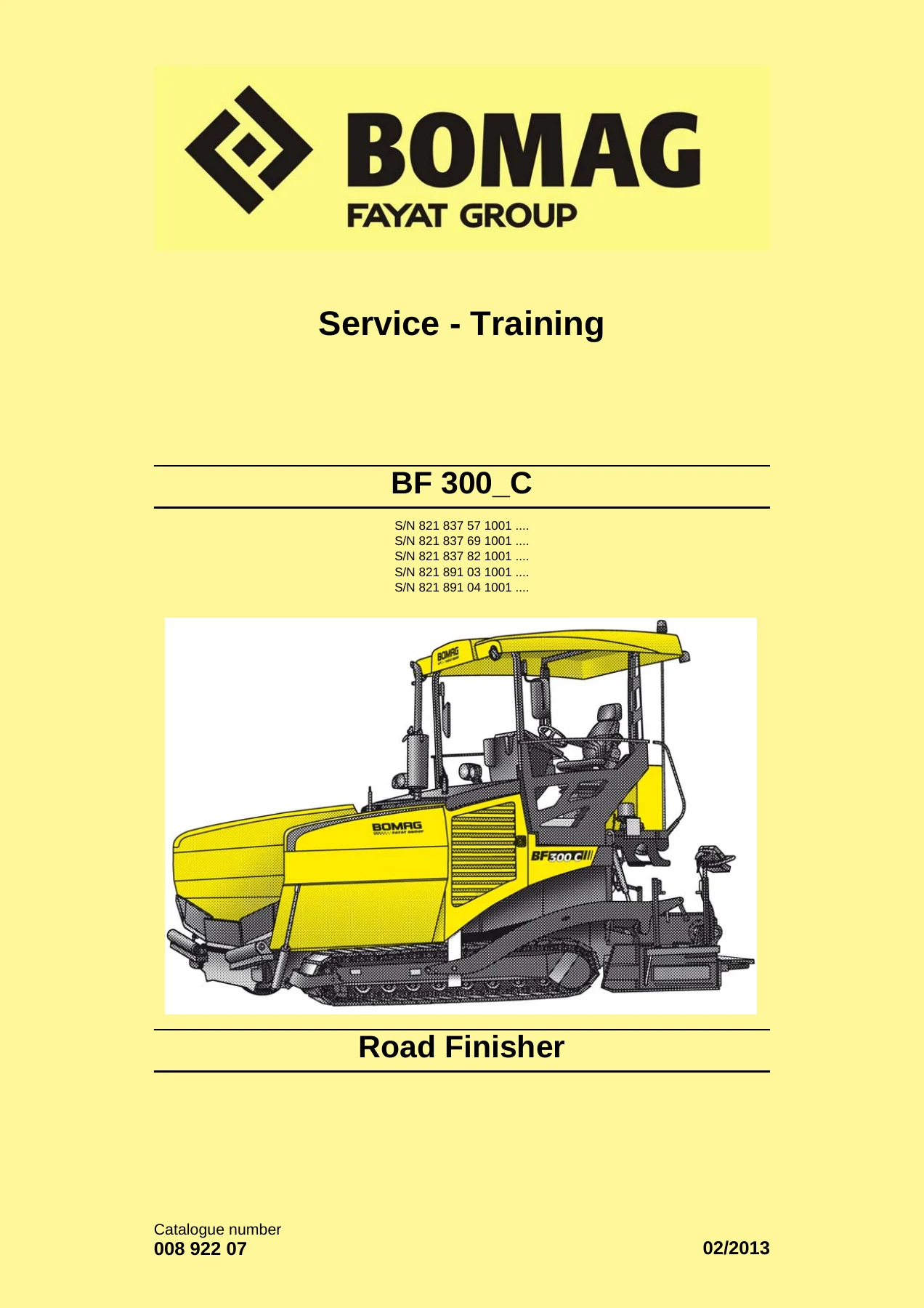
BOMAG BF 300 C Road Finisher Service Training Manual – Complete Workshop PDF
$39.95 Original price was: $39.95.$24.95Current price is: $24.95.
Full BOMAG BF 300 C road finisher service training manual, document 008 922 07, February 2013. Covers engine, travel drive, screed, hydraulics, electrics, input codes and circuit diagrams across 1050 pages.
Description
BOMAG BF 300 C Road Finisher Service Training Manual
This BOMAG BF 300 C Road Finisher Service Training Manual is the complete service training documentation for the BF 300 C tracked road finisher and its S340 variants. Published under document number 008 922 07 in February 2013, it covers every major system on the machine: the Kubota V3307 T diesel engine, the hydrostatic travel drive, the material hopper and scraper belts, the augers, the vibrating screed, the electrics and E-Plan wiring diagrams, the hydraulic circuits, and the central lubrication system. The manual runs to 1050 pages and is written for the technician working on the machine rather than for a general audience.
File Details
- Manual type: Service Training Manual
- Brand: BOMAG
- Model: BF 300 C / S340
- Language: English
- Page count: 1050
- File format: PDF
- Document number: 008 922 07
- Edition / date: February 2013
IMAGES PREVIEW
Chapters Covered
- General – introduction, safety regulations, general repair instructions, tightening torques
- Technical data – engine, travel pumps, travel motors, travel gear, service pump, tamper, vibration, auger, scraper belt, cleaning kit, noise and vibration values
- Maintenance – general notes, fuels and lubricants, running-in instructions, maintenance table
- E-Plan wiring diagrams – understanding E-Plan circuit diagrams, circuit symbols, identification of switch blocks, component designations, terminal designations
- Electrics – ECOMODE, glow plugs, speed sensors, oil pressure switch, coolant temperature switch, air filter vacuum switch, coolant float switch, charge control light, water separator, level sensor in diesel tank, fuses and fuse assignment, component overview, wiring looms, control elements, monitoring modules, functional block diagrams, voltage supply checks, diagnostics concept
- Input codes – display functions and operation, automatic calibration of travel system currents, teaching the E-throttle function, teaching the L.C.S. function, resetting to factory settings, showing stored faults, deleting the fault log, driving against the closed brake, adapting the engine speed, speed range change when cornering, deactivating and activating the speed sensors
- Replacement of components – procedures after replacing the ESX control, travel pumps and E-throttle actuator
- Engine – features, cooling system, thermostat, coolant level and change, engine oil and filter, fuel system and filter, water separator, generator V-belt, air filter, engine mounts, valve clearance, engine problems
- Material hopper – material flow, scraper belts, augers
- Vibrating screed – drawing arms, screed, tampers, vibrators, base plates, heating, crown profile
- Travel drive – track drive, frame, track tensioner, travel motor, reduction gear
- Cleaning kit – provision container, filter, pump, hose reel, spray gun, control panel
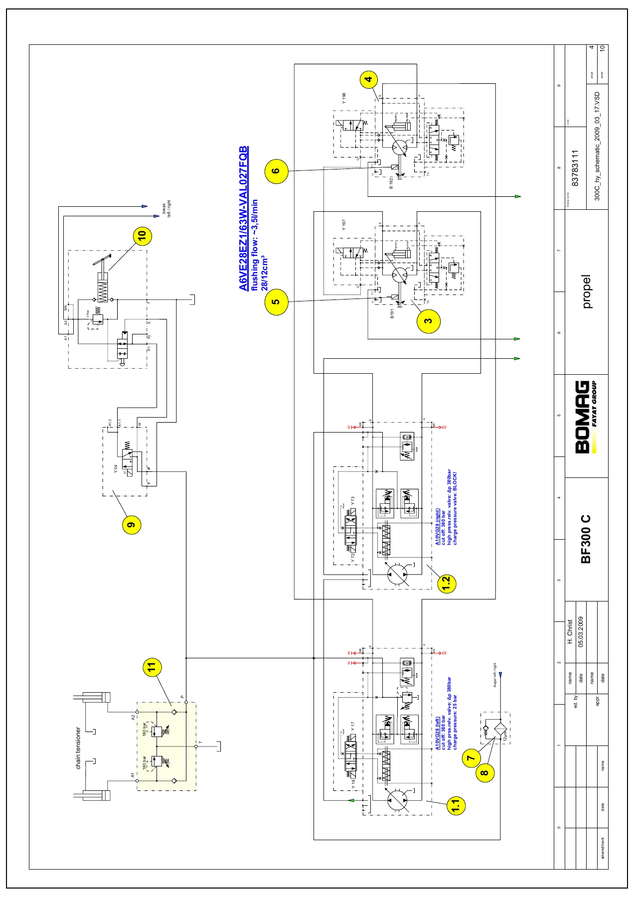
- Hydraulics – hydraulic circuit, travel pump A10VG28 EP, troubleshooting axial piston pumps, component overview, travel circuit, vibration and tamper drive, scraper belt drive, auger drive, cylinder functions, hydraulic oil level and changes
- Tests and adjustments – special tools, checking and adjusting vibration, tamping, scraper belts, augers, main screed, screed levelling, hopper wings, mobile screed
- Central lubrication system – filling the lubricant container, electric pump, integrated electronic control, progressive distributor, fault finding, repair of a blocked distributor
- Circuit diagrams – hydraulic diagram, electric circuit diagrams
For a technician working on a BF 300 C, this manual does more than list specifications. It explains the design and function of each assembly, gives the settings and tightening torques needed to work on it, and supplies the diagnostic codes and test procedures that let you confirm a repair is correct. The E-Plan section alone is worth the file: it shows how to read the wiring diagrams, trace a circuit through the terminal designations, and locate a fault without guesswork. The hydraulic chapter breaks the machine into its individual circuits, travel, vibration and tamping, scraper belt, auger and cylinder functions, so you can isolate a problem to one pump, one valve block or one motor before you start pulling lines.
Complete Bookmarks
The complete bookmarks in the βBOMAG BF 300 C Road Finisher Service Training Manual – Complete Workshop PDFβ are as follows:
+BF 300_Cp. 1
+BF 300_Cp. 1
+S/N 821 837 57 1001 ….p. 1
+1 Generalp. 7
+1.1 Introductionp. 8
+Documentationp. 8
+1 Operating and maintenance instructionsp. 8
+These safety regulations must be read and applied by every person involved in the repair /maintenance of this machine. The applicable accident prevention instructions and the safety regulations in the operating and maintenance instructions must be ad…p. 8
+Generalp. 9
+Important notesp. 9
+These safety regulations must be read and applied by every person involved in the repair /maintenance of this machine. The applicable accident prevention instructions and the safety regulations in the operating and maintenance instructions must be ad…p. 9
+Paragraphs marked like this contain technical information for the optimal economical use of the machine.p. 9
+Paragraphs marked like this highlight possible dangers for machines or parts of the machine.p. 9
+Paragraphs marked like this highlight possible dangers for persons.p. 9
+Paragraphs marked like this point out practices for safe and environmental disposal of fuels and lubricants as well as replacement parts.p. 9
+Generalp. 9
+l For repair and maintenance work move the machine on a firm base and shut it down.p. 9
+Transport work with cranes and lifting tacklep. 9
+Cranes must only be operated by instructed persons who had been trained in handling cranes.p. 9
+l Follow the operating instructions of the manufacturer when working with cranes.p. 9
+Precautions and codes of conduct for welding workp. 9
+Electric shock!p. 9
+l Check welding equipment and cables for damage before use (also the validity of inspection stickers).p. 9
+l In case of faults on the welding unit switch of the welding unit immediately and have it repaired by expert personnel.p. 10
+l Replace damaged insulating jaws and welding rod holders immediately.p. 10
+l Keep calm.p. 10
+Operation of high-voltage systemsp. 10
+The rules and statutory regulations valid in the corresponding do apply in addition to the notes given here.p. 10
+The high-voltage system must only be operated and serviced by qualified and authorized personnel.p. 10
+Possibility of injury or even death caused by electric shock:p. 10
+l if persons come into contact with live parts,p. 10
+l in case of faulty insulation of live parts,p. 10
+l inadequate, unsuitable insulation,p. 10
+l if melted parts flake off in case of short circuits.p. 10
+Old oilsp. 10
+l Wear protective clothes and safety gloves, if possible.p. 10
+It is strictly prohibited to drain off oil into the soil, the sewer system or into natural waters. Old oil must be disposed of according to applicable environmental regulations. If in doubt you should consult your local authorities.p. 11
+Hydraulicsp. 11
+l Always relieve the pressure in the hydraulic system before disconnecting any lines. Hydraulic oil escaping under pressure can penetrate the skin and cause severe injury.p. 11
+It is strictly prohibited to drain off oil into the soil, the sewer system or into natural waters. Oil oil must be disposed of according to applicable environmental regulations. If in doubt you should consult your local authorities.p. 11
+Fuelsp. 11
+Repair work shall only performed by appropriately trained personnel or by the after sales service of BOMAG.p. 11
+l Fire extinguishers charged with FOAM, COp. 11
+Hot fuelsp. 11
+l Allow the fuel to cool down, to prevent any contact with a hot fluid.p. 11
+Synthetic rubberp. 11
+l If the material is in such a state it must only be touched with special protective gloves. The protective gloves must be disposed of according to applicable environmental regulations immediately after use.p. 11
+Poisonous substancesp. 11
+Enginep. 12
+Do not work on the fuel system while the engine is running. (Danger to life!)p. 12
+l Maintenance and cleaning work on the engine must only be performed with the engine stopped and cooled down. Make sure that the electric system is switched off and sufficiently secured against being switched on again (e.g. pull off ignition key, att…p. 12
+Batteryp. 12
+l Always wear goggles and protective clothing to service or clean batteries! Battery acid can cause severe injury by cauterization when coming in contact with skin.p. 12
+Special safety regulationsp. 12
+l Use only genuine BOMAG spare parts for repair and maintenance work. Genuine spare parts and original accessories were specially developed, tested and approved for the machine.p. 12
+The values specified in the table apply for screws:p. 13
+Generalp. 13
+l Before removing or disassembling parts, assemblies, components or hoses mark these parts for easier assembly.p. 13
+The values specified in the table apply for screws:p. 13
+Generalp. 13
+l In approx. 10 % of the examined cases the problems were caused by control units.p. 13
+l Before changing any expensive components, such as control units, you should run a systematic trouble shooting session to eliminate any other possible fault sources. Knowledge in basic electrics is required for this purpose. If a fault was diagnosed…p. 13
+Electrics and weldingp. 14
+Before starting welding work you should disconnect the negative battery pole or interrupt the electric circuit with the main battery switch, disconnect the generator and pull the plugs off all control units in order to protect the electrical system o…p. 14
+l Disconnect the minus pole of the battery or interrupt the electric circuit with the main battery switch.p. 14
+The values specified in the table apply for screws:p. 14
+The values specified in the table apply for screws:p. 15
+The values specified in the table apply for screws:p. 16
+Repair work on hydraulic elements shall only performed by appropriately trained personnel or by the after sales service of BOMAG.p. 16
+Please notep. 16
+Cleanliness is of utmost importance. Dirt and other contaminations must strictly be kept out of the system.p. 16
+l Connections and screw fittings, filler neck covers and their immediate surrounding areas must be cleaned before removal.p. 16
+Before commissioningp. 16
+l Fill the housings of hydraulic pumps and motors with hydraulic oil. Use only hydraulic oils according to the specification in the maintenance instructions.p. 16
+Taking into operationp. 16
+l Bleed the hydraulic circuits.p. 16
+After taking into operationp. 16
+l Check fittings and flanges for leaks.p. 16
+The values specified in the table apply for screws:p. 17
+All fuel hoses have two layers of material, a reinforced rubber coating outside and an internal Viton hose. If a fuel hose has come loose one must make absolutely sure that the internal Viton layer has not been separated from the reinforced outer lay…p. 17
+The values specified in the table apply for screws:p. 17
+l Before assembling a new seal or gasket make sure that the sealing surface is free of pitting, flutes, corrosion or other damage.p. 17
+l Lubricate the sealing lips (2)p. 17
+If possible, use an assembly sleeve (1p. 17
+l Lubricate the outer rim (arrow 3p. 18
+l Press or knock the seal into the housing, until it is flush with the housing surface.p. 18
+If possible, use a "bell" (1p. 18
+The values specified in the table apply for screws:p. 18
+Feather keys may only be reused if they are free of damage.p. 18
+l Clean and thoroughly examine the feather key.p. 18
+The values specified in the table apply for screws:p. 19
+Ball and roller bearings may only be reused if they are free of damage and do not show any signs of wear.p. 19
+l If a ball or roller bearing of a bearing pair shows defects, both ball or roller bearings need to be replaced.p. 19
+When assembling the ball or roller bearing to the shaft load must only be applied to the inner race 1p. 19
+The values specified in the table apply for screws:p. 20
+Tighten nuts or screws with the tightening torques specified in the following tables of tightening torques. Tightening torques deviating from the ones in the table are specially mentioned in the repair instructions.p. 20
+l Nut of a higher strength can generally be used instead of nuts of a lower strength classification.p. 20
+l Before tightening you should lightly oil the thread, in order to ensure low friction movement.p. 20
+The first number corresponds with 1/100 of the nominal tensile strength (minimum tensile strength) in N/ mmp. 20
+l The nominal tensile strength is 12 X 100 N/mmp. 20
+When exceeding the lower yield point, the material will return to its original shape when being relieved (plastic deformation).p. 20
+l The lower tensile strength is 9/10 X 1200 N/mmp. 20
+However, these values are by no means identical with the tightening torques, which are to be set on a torque wrench. The corresponding calculation requires a higher effort and, in the end, depends on the materials to be bolted together.p. 20
+In a connection with a screw, these nuts 1p. 21
+Strength class of nutp. 21
+Strength class of associated screwp. 21
+4p. 21
+3.6, 4.6, 4.8p. 21
+5p. 21
+3.6, 4.6, 4.8p. 21
+6p. 21
+6.8p. 21
+8p. 21
+8.8p. 21
+9p. 21
+9.8p. 21
+10p. 21
+10.8p. 21
+12p. 21
+12.8p. 21
+The preceding "0" indicates that, due to their low height, nuts 2p. 21
+This standard contains strength classes (hardness classes) for nuts 3p. 21
+For small nutsp. 21
+l The 12 o'clock position is identified by a dot or the manufacturer's symbol.p. 21
+The screw head is marked with a stamped in, round cavity 3p. 22
+The values specified in the table apply for screws:p. 23
+l black oiledp. 23
+DACROMET is a surface protection that mainly consists of zinc and aluminium in a chromium oxide matrix. DACROMETIZATION provides excellent corrosion protection for metal surfaces by applying a mineral coating with metallic-silver appearance.p. 23
+Tightening torques for screws with metric unified threadp. 23
+Coefficient of friction m tot. = 0,14p. 23
+Screw dimensionp. 23
+Tightening torques Nmp. 23
+8.8p. 23
+10.9p. 23
+12.9p. 23
+M4p. 23
+3p. 23
+5p. 23
+5p. 23
+M5p. 23
+6p. 23
+9p. 23
+10p. 23
+M6p. 23
+10p. 23
+15p. 23
+18p. 23
+M8p. 23
+25p. 23
+35p. 23
+45p. 23
+M10p. 23
+50p. 23
+75p. 23
+83p. 23
+M12p. 23
+88p. 23
+123p. 23
+147p. 23
+M14p. 23
+137p. 23
+196p. 23
+235p. 23
+M16p. 23
+211p. 23
+300p. 23
+358p. 23
+M18p. 23
+290p. 23
+412p. 23
+490p. 23
+M20p. 23
+412p. 23
+578p. 23
+696p. 23
+M22p. 23
+560p. 23
+785p. 23
+942p. 23
+M24p. 23
+711p. 23
+1000p. 23
+1200p. 23
+M27p. 23
+1050p. 23
+1480p. 23
+1774p. 23
+M30p. 23
+1420p. 23
+2010p. 23
+2400p. 23
+Tightening torques for screws with metric unified fine threadp. 23
+Coefficient of friction m tot. = 0,14p. 23
+Screw dimensionp. 23
+Tightening torques Nmp. 23
+8.8p. 23
+10.9p. 23
+12.9p. 23
+M8 x 1p. 23
+26p. 23
+37p. 23
+48p. 23
+M10 x 1.25p. 23
+52p. 23
+76p. 23
+88p. 23
+M12 x 1,25p. 23
+98p. 23
+137p. 23
+126p. 23
+M12 x 1.5p. 23
+93p. 23
+127p. 23
+152p. 23
+M14 x 1.5p. 23
+152p. 23
+216p. 23
+255p. 23
+M16 x 1.5p. 23
+225p. 23
+318p. 23
+383p. 23
+M18 x 1.5p. 23
+324p. 23
+466p. 23
+554p. 23
+M20 x 1.5p. 23
+461p. 23
+628p. 23
+775p. 23
+M22 x 1.5p. 23
+618p. 23
+863p. 23
+1058p. 23
+M24 x 2p. 23
+780p. 23
+1098p. 23
+1294p. 23
+M27 x2p. 23
+1147p. 23
+1578p. 23
+1920p. 23
+M30 x 2p. 23
+1568p. 23
+2254p. 23
+2695p. 23
+Tightening torques for screws treated with anti-seizure paste OKS 240 (copper paste)p. 24
+Tightening torques for screws treated with anti-seizure paste OKS 240p. 24
+Screw dimensionp. 24
+Tightening torques Nmp. 24
+8.8p. 24
+10.9p. 24
+12.9p. 24
+M16p. 24
+169p. 24
+240p. 24
+287p. 24
+M16 x 1.5p. 24
+180p. 24
+255p. 24
+307p. 24
+M18p. 24
+232p. 24
+330p. 24
+392p. 24
+M18 x 1.5p. 24
+260p. 24
+373p. 24
+444p. 24
+M20p. 24
+330p. 24
+463p. 24
+557p. 24
+M20 x 1.5p. 24
+369p. 24
+502p. 24
+620p. 24
+M22p. 24
+448p. 24
+628p. 24
+754p. 24
+M22 x 1.5p. 24
+495p. 24
+691p. 24
+847p. 24
+M24p. 24
+569p. 24
+800p. 24
+960p. 24
+M24 x 2p. 24
+624p. 24
+879p. 24
+1036p. 24
+M27p. 24
+840p. 24
+1184p. 24
+1520p. 24
+M27 X 2p. 24
+918p. 24
+1263p. 24
+1536p. 24
+M30p. 24
+1136p. 24
+1608p. 24
+1920p. 24
+M30 x 2p. 24
+1255p. 24
+1804p. 24
+2156p. 24
+3/4β – 10 UNCp. 24
+276p. 24
+388p. 24
+464p. 24
+3/4β – 16 UNCp. 24
+308p. 24
+432p. 24
+520p. 24
+Tightening torques for wheel nuts (fine thread)p. 24
+Coefficient of friction m tot. = 0,14p. 24
+Thread diameterp. 24
+Tightening torques Nmp. 24
+10.9p. 24
+M12x1.5p. 24
+100p. 24
+M14x1.5p. 24
+150p. 24
+M18x1.5p. 24
+300 – 350p. 24
+M20x1.5p. 24
+400 – 500p. 24
+M22x1.5p. 24
+500 – 600p. 24
+l black oiledp. 25
+The difference between Withworth and UNF/UNC threads is the fact that UNF and UNC threads have 60Β° flanks, as the metric ISO-thread, whereas Withworth has a flank of only 55Β°.p. 25
+Tightening torques for screws with UNC thread, UNC Unified Coarse Thread Series, American Unified Coarse Threadp. 25
+Tightening torques for screws with UNC thread,p. 25
+Coefficient of friction m tot. = 0,14p. 25
+Screw dimensionp. 25
+Tightening torques Nmp. 25
+8.8p. 25
+10.9p. 25
+12.9p. 25
+1/4β – 20p. 25
+11p. 25
+15p. 25
+19p. 25
+5/16β – 18p. 25
+23p. 25
+32p. 25
+39p. 25
+3/8β – 16p. 25
+39p. 25
+55p. 25
+66p. 25
+7/16β – 14p. 25
+62p. 25
+87p. 25
+105p. 25
+1/2β – 13p. 25
+96p. 25
+135p. 25
+160p. 25
+9/16β – 12p. 25
+140p. 25
+200p. 25
+235p. 25
+5/8β – 11p. 25
+195p. 25
+275p. 25
+330p. 25
+3/4β – 10p. 25
+345p. 25
+485p. 25
+580p. 25
+7/8β – 9p. 25
+560p. 25
+770p. 25
+940p. 25
+1β – 8p. 25
+850p. 25
+1200p. 25
+1450p. 25
+1 1/8β – 7p. 25
+1200p. 25
+1700p. 25
+2000p. 25
+1 1/4β – 7p. 25
+1700p. 25
+2400p. 25
+2900p. 25
+1 3/8β – 6p. 25
+2200p. 25
+3100p. 25
+3700p. 25
+1 1/2β – 6p. 25
+3000p. 25
+4200p. 25
+5100p. 25
+Tightening torques for screws with UNF thread, UNF Unified National Fine Thread Series, American Unified Fine Threadp. 25
+Tightening torques for screws with UNF thread,p. 25
+Coefficient of friction m tot. = 0,14p. 26
+Screw dimensionp. 25
+Tightening torques Nmp. 25
+8.8p. 25
+10.9p. 25
+12.9p. 25
+1/4β – 28p. 25
+13p. 25
+18p. 25
+22p. 25
+5/16β – 24p. 25
+25p. 25
+35p. 25
+42p. 25
+3/8β – 24p. 25
+45p. 25
+63p. 25
+76p. 25
+7/16β – 20p. 25
+70p. 25
+100p. 25
+120p. 25
+1/2β – 20p. 25
+110p. 25
+155p. 25
+185p. 25
+9/16β – 18p. 25
+155p. 25
+220p. 25
+260p. 25
+5/8β – 18p. 25
+220p. 25
+310p. 25
+370p. 25
+3/4β – 16p. 25
+385p. 25
+540p. 25
+650p. 25
+7/8β -14p. 25
+620p. 25
+870p. 25
+1050p. 25
+1β – 12p. 26
+930p. 26
+1300p. 26
+1600p. 26
+1 1/8β – 12p. 26
+1350p. 26
+1900p. 26
+2300p. 26
+1 1/4β – 12p. 26
+1900p. 26
+2700p. 26
+3200p. 26
+1 3/8β – 12p. 26
+2600p. 26
+3700p. 26
+4400p. 26
+1 1/2β – 12p. 26
+3300p. 26
+4600p. 26
+5600p. 26
+2 Technical datap. 27
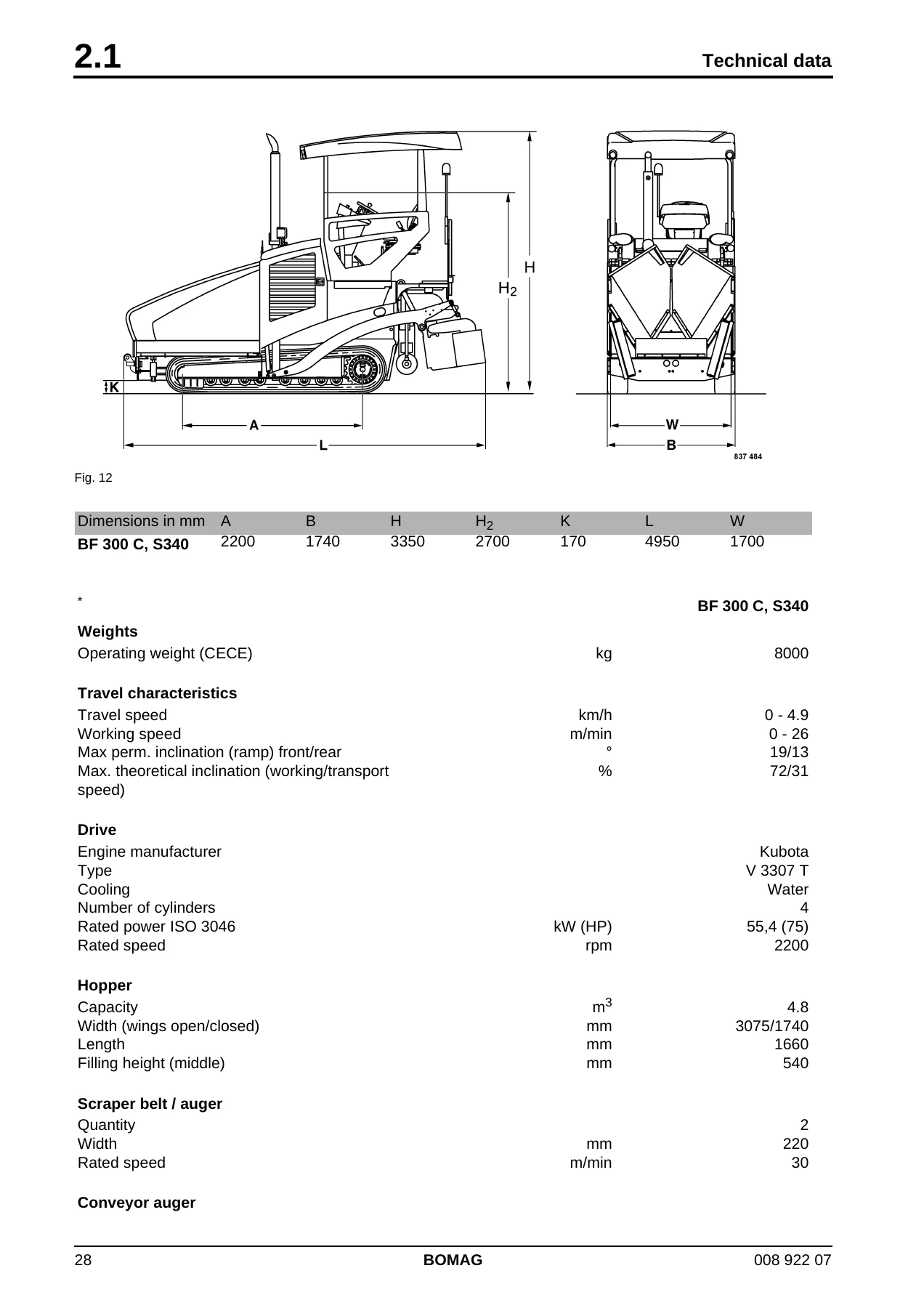
+Dimensions in mmp. 28
+Ap. 28
+Bp. 28
+Hp. 28
+H2p. 28
+Hp. 28
+Kp. 28
+Lp. 28
+Wp. 28
+BF 300 C, S340p. 28
+2200p. 28
+1740p. 28
+3350p. 28
+2700p. 28
+170p. 28
+4950p. 28
+1700p. 28
+The right for technical modifications remains reservedp. 28
+BF 300 C, S340p. 28
+Weightsp. 28
+Operating weight (CECE)p. 28
+kgp. 28
+8000p. 28
+Travel characteristicsp. 28
+Travel speedp. 28
+km/hp. 28
+0 – 4.9p. 28
+Working speedp. 28
+m/minp. 28
+0 – 26p. 28
+Max perm. inclination (ramp) front/rearp. 28
+Β°p. 28
+19/13p. 28
+Max. theoretical inclination (working/transport speed)p. 28
+%p. 28
+72/31p. 28
+Drivep. 28
+Engine manufacturerp. 28
+Kubotap. 28
+Typep. 28
+V 3307 Tp. 28
+Coolingp. 28
+Waterp. 28
+Number of cylindersp. 28
+4p. 28
+Rated power ISO 3046p. 28
+kW (HP)p. 28
+55,4 (75)p. 28
+Rated speedp. 28
+rpmp. 28
+2200p. 28
+Hopperp. 28
+Capacityp. 28
+m3p. 28
+mp. 28
+4.8p. 28
+Width (wings open/closed)p. 28
+mmp. 28
+3075/1740p. 28
+Lengthp. 28
+mmp. 28
+1660p. 28
+Filling height (middle)p. 28
+mmp. 28
+540p. 28
+Scraper belt / augerp. 28
+Quantityp. 28
+2p. 28
+Widthp. 28
+mmp. 28
+220p. 28
+Rated speedp. 28
+m/minp. 28
+30p. 28
+Conveyor augerp. 28
+Quantityp. 29
+2p. 29
+Auger diameterp. 29
+mmp. 29
+280p. 29
+Rated speedp. 29
+rpmp. 29
+100p. 29
+Screedp. 29
+Width of screedp. 29
+mmp. 29
+1700 – 3400p. 29
+Max. working widthp. 29
+mmp. 29
+4000p. 29
+Min. paving width with reducing skidsp. 29
+mmp. 29
+750p. 29
+Mat heightp. 29
+mmp. 29
+250p. 29
+Smooth plate depthp. 29
+mmp. 29
+305p. 29
+Smooth plate thicknessp. 29
+mmp. 29
+12p. 29
+Heatingp. 29
+electricp. 29
+Crownp. 29
+%p. 29
+-3 to +4.5p. 29
+Tamper frequencyp. 29
+Hzp. 29
+0 – 30p. 29
+Vibration frequencyp. 29
+Hzp. 29
+20 – 50p. 29
+Basic weightp. 29
+kgp. 29
+1000p. 29
+Max. weightp. 29
+kgp. 29
+1200p. 29
+Filling capacitiesp. 29
+Fuelp. 29
+lp. 29
+100p. 29
+Hydraulic oilp. 29
+lp. 29
+80p. 29
+Engine oilp. 29
+lp. 29
+11.2p. 29
+Additional engine datap. 30
+Combustion principlep. 30
+4-stroke dieselp. 30
+Low idle speedp. 30
+rpmp. 30
+950 – 1000p. 30
+High idle speedp. 30
+rpmp. 30
+2150 – 2250p. 30
+Valve clearance intakep. 30
+mmp. 30
+0.15 Β± 0.02p. 30
+Valve clearance exhaustp. 30
+mmp. 30
+0.15 Β± 0.02p. 30
+Injection valves opening pressurep. 30
+barp. 30
+1. Phase 186 / 2. Phase 225p. 30
+Valve seat leak tightness injection valvesp. 30
+barp. 30
+At a pressure of (166. bar, the valve seat must be fuel leak tightp. 30
+Travel pumpsp. 30
+Manufacturerp. 30
+Bosch-Rexrothp. 30
+Typep. 30
+A10VGp. 30
+Quantityp. 30
+2p. 30
+Systemp. 30
+Axial piston/swash platep. 30
+Max. displacementp. 30
+cm3/revp. 30
+cmp. 30
+28p. 30
+Max. flow capacityp. 30
+l/minp. 30
+109p. 30
+Maximum pressurep. 30
+barp. 30
+370 – 390p. 30
+Charge pressurep. 30
+barp. 30
+24 – 26p. 30
+High pressure limitationp. 30
+Pressure override valvep. 30
+Travel motorsp. 30
+Manufacturerp. 30
+Bosch-Rexrothp. 30
+Typep. 30
+A6VEp. 30
+Quantityp. 30
+2p. 30
+Systemp. 30
+Axial piston/bent axlep. 30
+Max. displacement (stage 1)p. 30
+cm3/Up. 30
+cmp. 30
+28.1p. 30
+Min. displacement (stage 2)p. 30
+cm3/Up. 30
+cmp. 30
+0p. 30
+Travel gearp. 30
+Manufacturerp. 30
+Bonfigliolip. 30
+Typep. 30
+705 Cp. 30
+Systemp. 30
+Planetary gear with integrated brakep. 30
+Reduction ratiop. 30
+1:80p. 30
+Quantityp. 30
+2p. 30
+Continuous torquep. 30
+Nmp. 30
+6000p. 30
+Maximum torquep. 30
+Nmp. 30
+13500p. 30
+Maximum input speedp. 30
+rpmp. 30
+5600p. 30
+Brake: Brake torquep. 30
+Nmp. 30
+180-220p. 30
+Brake releasing pressurep. 30
+barp. 30
+24 – 26p. 30
+Service pumpp. 30
+Manufacturerp. 30
+Bosch-Rexrothp. 30
+Typep. 30
+A10VOp. 30
+Systemp. 30
+Gear pumpp. 30
+Quantityp. 30
+1p. 30
+Displacementp. 30
+cm3/revp. 30
+cmp. 30
+190p. 30
+Fastening flangep. 30
+SAE A 2-holep. 30
+Nominal pressurep. 30
+barp. 30
+276p. 30
+Maximum speedp. 30
+rpmp. 30
+3000p. 30
+Pump –> tamper and vibration (stage 1)p. 30
+Manufacturerp. 30
+Haldexp. 30
+Typep. 30
+WP09p. 30
+Systemp. 30
+Gear pumpp. 30
+Quantityp. 30
+1p. 30
+Displacementp. 30
+cm3/revp. 30
+cmp. 30
+190p. 30
+Nominal pressurep. 31
+barp. 31
+276p. 31
+Maximum speedp. 31
+rpmp. 31
+3000p. 31
+Tamper motorp. 31
+Manufacturerp. 31
+Sauer Danfossp. 31
+Typep. 31
+SNM2p. 31
+Systemp. 31
+Gear motorp. 31
+Displacementp. 31
+cm3/Up. 31
+cmp. 31
+14.4p. 31
+Maximum pressurep. 31
+barp. 31
+280p. 31
+Nominal pressurep. 31
+barp. 31
+250p. 31
+Rated speedp. 31
+rpmp. 31
+1800 – 2000p. 31
+Vibration motorp. 31
+Manufacturerp. 31
+Sauer Danfossp. 31
+Typep. 31
+SNM2p. 31
+Systemp. 31
+Gear motorp. 31
+Displacementp. 31
+cm3/Up. 31
+cmp. 31
+8.4p. 31
+Maximum pressurep. 31
+barp. 31
+280p. 31
+Nominal pressurep. 31
+barp. 31
+250p. 31
+Rated speedp. 31
+rpmp. 31
+2650 – 2850p. 31
+Pump –> auger drive left (stage 2)p. 31
+Manufacturerp. 31
+Haldexp. 31
+Typep. 31
+WP09p. 31
+Systemp. 31
+Gear pumpp. 31
+Quantityp. 31
+1p. 31
+Displacementp. 31
+cm3/revp. 31
+cmp. 31
+80p. 31
+Pressurep. 31
+barp. 31
+230 – 250p. 31
+Maximum speedp. 31
+rpmp. 31
+4000p. 31
+Motor for augersp. 31
+Manufacturerp. 31
+Sauer Danfossp. 31
+Typep. 31
+OMS 160p. 31
+Systemp. 31
+Orbital motorp. 31
+Max. displacement.p. 31
+cm3/revp. 31
+cmp. 31
+160p. 31
+Rated speedp. 31
+rpmp. 31
+80 – 84p. 31
+Quantityp. 31
+2p. 31
+Pump 3-stage (drive of right auger, as well as conveyor belt left & right)p. 31
+Manufacturerp. 31
+Haldexp. 31
+Typep. 31
+WP09p. 31
+Systemp. 31
+Gear pumpp. 31
+Quantityp. 31
+1p. 31
+Displacementp. 31
+cm3/revp. 31
+cmp. 31
+80p. 31
+Pressurep. 31
+barp. 31
+230 – 250p. 31
+Maximum speedp. 31
+rpmp. 31
+4000p. 31
+Scraper belt motorsp. 31
+Manufacturerp. 31
+Sauer Danfossp. 31
+Typep. 31
+OMS 160p. 31
+Systemp. 31
+Orbital motorp. 31
+Max. displacement.p. 32
+cm3/revp. 32
+cmp. 32
+160p. 32
+Rated speedp. 32
+rpmp. 32
+60 – 64p. 32
+Quantityp. 32
+2p. 32
+Pump for cleaning kitp. 32
+Manufacturerp. 32
+Flowjetp. 32
+Typep. 32
+Duplex 2 seriesp. 32
+Systemp. 32
+Dual piston pumpp. 32
+Quantityp. 32
+1p. 32
+Displacement (high pressure variant)p. 32
+l/minp. 32
+8.32p. 32
+Displacement (medium and low pressure variant)p. 32
+l/minp. 32
+6.05p. 32
+Maximum pressurep. 32
+barp. 32
+6.8p. 32
+Noise valuep. 33
+Lp. 33
+Lp. 33
+Wear your personal noise protection means (ear defenders) before starting operation.p. 33
+Vibration valuep. 33
+The weighted effective acceleration value determined acc. to ISO 7096, isp. 33
+The weighted effective acceleration value, determined acc. to EN 500/ISO 5349, isp. 33
+3 Maintenancep. 35
+3.1 General notes on maintenancep. 36
+When performing maintenance work always comply with the appropriate safety regulations.p. 36
+l Always clean machine and engine thoroughly before starting maintenance work.p. 36
+During maintenance work catch all oils and fuels and do not let them seep into the ground or into the sewage system. Dispose of oils and fuels environmentally.p. 36
+Notes on the fuel systemp. 36
+l Keep fuel free of contaminants and water, since this will damage the injection elements of the engine.p. 36
+Notes on the performance of the enginep. 36
+Notes on the cooling systemp. 36
+Notes on the hydraulic systemp. 36
+l If, during the daily inspection of the oil level the hydraulic oil level is found to have dropped, check all lines, hoses and components for leaks.p. 36
+3.2 Fuels and lubricantsp. 37
+Engine oilp. 37
+Only engine oils of APIp. 37
+Engine oils of API-classification CF-4, CG-4 and CH-4 must not be used.p. 37
+Ambient temperaturep. 37
+Viscosityp. 37
+Viscosityp. 37
+over 25 Β°C!p. 37
+SAE 30p. 37
+0Β°C to 25Β°Cp. 37
+SAE 20p. 37
+below 0 Β°Cp. 37
+SAE 10Wp. 37
+Fuelsp. 37
+Do not use any fuels with a sulphur content of more than 1,0% (10000ppm).p. 37
+Since this engine complies with the exhaust gas standard acc. to EPAp. 37
+Fire hazard!p. 37
+Coolantp. 37
+Do not mix different coolants and additives of any other kind.p. 38
+50%p. 38
+Coolant must be disposed of environmentally.p. 38
+Mineral oil based hydraulic oilp. 38
+The hydraulic system is operated with hydraulic oil HV 46 (ISO) with a kinematic viscosity of 46 mmp. 38
+Gear oilp. 38
+For the gearboxes use only ,ulti-purpose gear oils ISO VG 220 of API-GL5-class with a minimum viscosity of 20 mmp. 38
+Lubrication greasep. 38
+Assemblyp. 39
+Fuel or lubricantp. 39
+Quantityp. 39
+Summerp. 39
+Winterp. 39
+Attentionp. 39
+Attentionp. 39
+Motorp. 39
+– Engine oilp. 39
+Engine oil API: CF or CI-4p. 39
+approx. 11.2 litresp. 39
+SAE 10W-40 (-20 Β°C to +40 Β°C)p. 39
+SAE 10W-30 (-15 Β°C to +30 Β°C)p. 39
+SAE 15W-40 (-15 Β°C to + 40 Β°C)p. 39
+SAE 30 (+5 Β°C to +30 Β°C)p. 39
+SAE 10 (-30 Β°C to -5 Β°C)p. 39
+– Fuelp. 39
+Dieselp. 39
+Winter diesel fuelp. 39
+approx. 100 litresp. 39
+– Coolantp. 39
+Mixture of water and anti-freeze agentp. 39
+approx. 14 litresp. 39
+Hydraulic systemp. 39
+Hydraulic oil (ISO), HLP 46p. 39
+approx. 80 litresp. 39
+Crawler track drive gearp. 39
+Gear oil SAE 80W-140, API GL-5p. 39
+approx. 3.2 l eachp. 39
+Lubrication points, generalp. 39
+High pressure grease (lithium saponified)p. 39
+as requiredp. 39
+The following maintenance work must be performed when running in new machines or overhauled engines:p. 40
+Up to approx. 250 operating hours check the engine oil level twice every day.p. 40
+l Retighten the V-beltp. 40
+l Change engine oil and oil filter cartridgep. 40
+l Tighten all bolted connections on air intake, exhaust, oil sump and engine mountsp. 40
+No.p. 41
+Maintenance workp. 41
+Commentp. 41
+every 10 operating hours, dailyp. 41
+every 50 oper. hoursp. 41
+every 250 oper. hoursp. 41
+every 500 oper. hoursp. 41
+every 1000 oper. hoursp. 41
+every 2000 oper. hoursp. 41
+every 3000 oper. hoursp. 41
+as requiredp. 41
+5.6p. 41
+Checking the engine oil levelp. 41
+Dipstick markp. 41
+Xp. 41
+5.7p. 41
+Check the fuel levelp. 41
+Instrument clusterp. 41
+Xp. 41
+5.8p. 41
+Check the coolant levelp. 41
+Xp. 41
+5.9p. 41
+Check the hydraulic oil levelp. 41
+Inspection glassp. 41
+Xp. 41
+5.10p. 41
+Lubricate the machinep. 41
+Xp. 41
+5.11p. 41
+Check fuel lines and clampsp. 41
+Xp. 41
+5.12p. 41
+Service the generator V-beltp. 41
+Xp. 41
+5.13p. 41
+Check the radiator hoses and hose clampsp. 41
+Xp. 41
+5.14p. 41
+Service the scraper beltp. 41
+Xp. 41
+5.15p. 41
+Service the scraper belt drive chainp. 41
+Xp. 41
+5.16p. 41
+Service the augerp. 41
+Xp. 41
+5.17p. 41
+Grease the gliding surface of the screed mobile sectionp. 41
+Xp. 41
+5.18p. 41
+Lubricate the machinep. 41
+Xp. 41
+5.19p. 41
+Check the central lubrication system, top upp. 41
+Xp. 41
+5.20p. 41
+Clean the cooling fins on engine and hydraulic oil coolerp. 41
+Xp. 41
+5.21p. 41
+Check the oil level in track drive gearp. 41
+Xp. 41
+5.22p. 41
+Service the battery, check the main battery switchp. 41
+pole greasep. 41
+Xp. 41
+5.23p. 41
+Checking the condition and tension of the screed heating generator V-belt, tensioning and if necessary replacing the V-beltp. 41
+Xp. 41
+5.24p. 41
+Change engine oil and oil filter cartridgep. 41
+min. 1x per yearp. 41
+Xp. 41
+5.25p. 41
+Check the anti-freeze concentration and the condition of the coolantp. 41
+Xp. 41
+5.26p. 41
+Replace the fuel filterp. 41
+Xp. 41
+5.27p. 42
+Change the fuel filter, bleed the fuel systemp. 42
+Xp. 42
+5.28p. 42
+Drain the fuel tank sludgep. 42
+Xp. 42
+5.29p. 42
+Check track, track drivep. 42
+Xp. 42
+5.30p. 42
+Check, adjust tamper bar and floor platesp. 42
+Xp. 42
+5.31p. 42
+Check, adjust the valve clearancep. 42
+Intake and exhaust valve: 0.15 mmp. 42
+Xp. 42
+5.32p. 42
+Change hydraulic oil and filterp. 42
+at least every 2 yearsp. 42
+Xp. 42
+5.33p. 42
+Check the engine mountsp. 42
+Xp. 42
+5.34p. 42
+Oil change in track drive gearp. 42
+see foot notep. 42
+Xp. 42
+5.35p. 42
+Checking hopper, scrapers and rubber apronp. 42
+Xp. 42
+5.36p. 42
+Change the coolantp. 42
+Xp. 42
+5.37p. 42
+Check the fuel injection nozzlesp. 42
+only by authorized service personnelp. 42
+Xp. 42
+5.38p. 42
+Check the turbo chargerp. 42
+only by authorized service personnelp. 42
+Xp. 42
+5.39p. 42
+Check the fuel injection pumpp. 42
+only by authorized service personnelp. 42
+Xp. 42
+5.40p. 42
+Air filter maintenancep. 42
+at least 1x every year, safety cartridge at least every 2 yearsp. 42
+Xp. 42
+5.41p. 42
+Check, clean the water separatorp. 42
+Xp. 42
+5.42p. 42
+Replace heating elementsp. 42
+Xp. 42
+5.43p. 42
+Preparing the machine for a longer restp. 42
+Xp. 42
+5.44p. 42
+Tightening torquesp. 42
+Xp. 42
+4 E-Plan wiring diagramsp. 43
+Electric circuit diagramsp. 44
+Electric circuit diagrams are graphic presentations of control logical conditions in the electric system. They do not contain any information on the type of wiring, their purpose is solely the clarification of control logics.p. 44
+l Number and type of individual elements in the examined electric circuit, such as plug connectors, fuses, switches, consumers, relays, etc.p. 44
+Structure of a wiring diagramp. 44
+l Cover sheet, see section "Cover sheet"p. 44
+The structuring symbol overview is NOT present in circuit diagrams, which are sorted by systems and local identification!p. 44
+l Sheets with illustration of function, see section"Sheets with illustration of function"p. 44
+The cover sheet, see examplep. 45
+The table of contents, see examplep. 46
+l The main reading direction is sheet by sheet, from top to bottom and from left to right.p. 47
+l BOMAG used the resolved type of representation. In this case parts and components with different functions, which belong to the same components (e.g. relay coil and relay contact), can be represented on different sheets. Cross-references, which ref…p. 47
+Current pathsp. 47
+Current pathsp. 47
+l Current paths are successively numbered from 0 to 9.p. 47
+Potential cross referencesp. 47
+l Potential cross references serve the purpose of tracking signals, which are transmitted from one representation of a function to another. Potential cross-references may additionally have structuring symbols assigned to them.p. 47
+Example: Potential 15_54 +SEAT/16.1 (on sheet 4, current path 8) continues to the right on sheet 16, current path 1.p. 47
+Relay cross referencesp. 48
+l Relay cross references serve the tracking of signals, which need to be tracked for components with outgoing contacts. A mimic diagram with information about the contact types of a relay and their positions in the wiring diagram is additionally atta…p. 48
+Example: The relay cross-reference (p. 48
+The list of components, see examplep. 49
+l Components are marked with a combination of letters and numbers. The identification with letters follows the standard DIN – EN 61346 T1-T2. A component identification (BMK), e.g.: βS04β always identifies the same component. In this context the …p. 49
+Component identifications are used in both the electrical and the hydraulic documentation and are identical.p. 49
+The overview of terminal strips, see axamplep. 50
+The overview of plugs, see examplep. 51
+l Contact numberingp. 51
+The overview of pins, see examplep. 52
+Circuit symbolp. 53
+1 Current sourcep. 53
+Different symbols are used to simplify the differentiation of terminal strips 11p. 53
+Plugs are mainly used to connect two wiring looms or to connect a wiring loom with a component with cable connection and mating plug.p. 53
+Black-Box representationp. 54
+Identification of externally supplied documentationp. 54
+PLC representationp. 54
+Example: -X0 36 and -X0 37p. 55
+Switches of modular designp. 56
+l For normally open contacts the contact symbols "_3/_4" are used.p. 56
+The designation of components in the wiring diagram groups several electrical parts of the machine in one group. The components can be identified by the following table.p. 57
+Component designationp. 57
+Meaningp. 57
+Ap. 57
+Interval switch, indicator relay, modules, electronic componentp. 57
+Bp. 57
+Pressure, pressure differential, temperature switches and sensors, transducersp. 57
+Cp. 57
+Capacitorp. 57
+Ep. 57
+Headlights, heater, air conditioning condenserp. 57
+Fp. 57
+Fusesp. 57
+Gp. 57
+Battery, generatorp. 57
+Hp. 57
+Control lights, warning buzzer, warning lightp. 57
+Kp. 57
+Relaysp. 57
+Mp. 57
+Starter, pumps, motorsp. 57
+Pp. 57
+Operating hour meter, general gaugesp. 57
+Rp. 57
+Transducers, resistorsp. 57
+Sp. 57
+Switches, momentary contact switchesp. 57
+Vp. 57
+Diodep. 57
+Xp. 57
+Terminalp. 57
+Yp. 57
+Solenoid valvesp. 57
+l For easier connection work almost every connection on a consumer or switch used in a motor vehicle has a terminal designation. In Germany the designation of the individual connection terminals is determined by the standard DIN 72552. The following …p. 58
+Terminal designationp. 58
+Meaningp. 58
+15p. 58
+Switch plus (after battery) : Output of ignition switchp. 58
+15ap. 58
+Output from dropping resistor to ignition coil and starterp. 58
+17p. 58
+Preheating starter switch, preheatingp. 58
+19p. 58
+Preheating starter switch, startingp. 58
+30p. 58
+Battery plus directp. 58
+30ap. 58
+Battery changeover relay 12V / 24V, input from battery 2 plusp. 58
+31p. 58
+Battery minus direct or groundp. 58
+31ap. 58
+Battery changeover relay 12V / 24V return line to battery 2 minusp. 58
+31bp. 58
+Return line to battery minus or ground via switch or relay (switched minus)p. 58
+31cp. 58
+Battery changeover relay 12V / 24V return line to battery 1 minusp. 58
+49p. 58
+Input flasher relayp. 58
+49ap. 58
+Output flasher relayp. 58
+49bp. 58
+Flasher relay output 2nd flasher circuitp. 58
+49cp. 58
+Flasher relay output 3rd flasher circuitp. 58
+50p. 58
+Starter, starter controlp. 58
+50ap. 58
+Battery changeover relay, output for starter controlp. 58
+53p. 58
+Wiper motor input (+)p. 58
+53ap. 58
+Wiper motor (+) end limit shut downp. 58
+53bp. 58
+Wiper shunt windingp. 58
+56p. 58
+Head lightp. 58
+56ap. 58
+Head light, travel light and travel light controlp. 58
+56bp. 58
+Head lights, dimmed head lightp. 58
+56dp. 58
+Head lights, flash lightp. 58
+57p. 58
+Parking light for motor cycles (abroad also for cars and trucks)p. 58
+57ap. 58
+Parking lightp. 58
+57Lp. 58
+Parking light leftp. 58
+57Rp. 58
+Parking light rightp. 58
+58p. 58
+Side lights, tail light, number plate light, dashboard lightp. 58
+58bp. 58
+Tail light changeover for single axle trailersp. 58
+58cp. 58
+Trailer plug for single core wired and trailer fused tail lightp. 58
+58dp. 58
+Adjustable dashboard light, tail light and side lightp. 58
+58Lp. 58
+Side light, leftp. 58
+58Rp. 58
+Side light, rightp. 58
+61p. 58
+Generator controlp. 58
+75p. 58
+Radio, cigarette lighterp. 58
+76p. 58
+Loudspeakerp. 58
+87p. 58
+Relay contact on breaker and two-way contact, inputp. 58
+87ap. 59
+Relay contact on breaker and two-way contact, output 1 (breaker side)p. 59
+87bp. 59
+Relay contact on breaker and two-way contact, output 2p. 59
+87cp. 59
+Relay contact on breaker and two-way contact, output 3p. 59
+87zp. 59
+Relay contact on breaker and two-way contact, input 1p. 59
+87yp. 59
+Relay contact on breaker and two-way contact, input 2p. 59
+87xp. 59
+Relay contact on breaker and two-way contact, input 3p. 59
+88p. 59
+Relay contact for makerp. 59
+88ap. 59
+Relay contact on maker and two-way contact, (maker side) output 1p. 59
+88bp. 59
+Relay contact on maker and two-way contact, (maker side) output 2p. 59
+88cp. 59
+Relay contact on maker and two-way contact, (maker side) output 3p. 59
+88zp. 59
+Relay contact on maker, input 1p. 59
+88yp. 59
+Relay contact on maker, input 2p. 59
+88xp. 59
+Relay contact on maker, input 3p. 59
+B+p. 59
+Battery positivep. 59
+B-p. 59
+Battery minusp. 59
+D+p. 59
+Dynamo Plusp. 59
+D-p. 59
+Dynamo Minusp. 59
+DFp. 59
+Dynamo field (generator excitation current)p. 59
+DF1p. 59
+Dynamo field 1 (generator excitation current)p. 59
+DF2p. 59
+Dynamo field 2 (generator excitation current)p. 59
+5 Electricsp. 61
+The actuating mechanism must be set to the correct end stops before initial start-up of the engine. See chapter "Electrics finisher input codes" section "Input codes E-throttle teaching"p. 63
+The actuator M39 acts directly on the motor power leverp. 63
+The motor is a permanently controlled DC-motor, which is triggered by the ESX-control A34 via the changeover relay K176 (1)p. 63
+l travel pressure (travel pressure sensor B112)p. 63
+l Switching on the screed heatingp. 63
+During the pre-heating and starting process the glow plugs are energized through relay K14.p. 65
+1 Glow plugsp. 65
+l Use a continuity tester to measure the resistance between glow plug connection and glow plug housing.p. 65
+l Remove the glow plug.p. 65
+l Use a continuity tester to measure the resistance between glow plug connection and glow plug housing.p. 65
+l If the measured value does not correspond with the factory specification, the glow plug (29p. 65
+Factory specification for resistance approx. 0.95 Ohm in cold condition.p. 65
+Align the recess to the connecting side when assembling the seal (1)p. 65
+The BF300_p. 66
+l At a pressure of less than 0.4 bar the oil pressure switch switches to motor ground.p. 67
+n redp. 67
+n redp. 67
+l Should the engine overheat, the temperature switch will switch to engine ground.p. 67
+b redp. 67
+b redp. 67
+l The vacuum switch 1p. 68
+a yellowp. 68
+a yellowp. 68
+l In case of a too low coolant level the float switch will switch to ground.p. 68
+o redp. 68
+o redp. 68
+l The control lamp lights up if a ground signal is applied to the generator terminal (L).p. 69
+p yellowp. 69
+p yellowp. 69
+l yellowp. 69
+l yellowp. 69
+l With water in the filter the sensor will switch to ground.p. 70
+k yellowp. 70
+k yellowp. 70
+l The analog level switch is a variable resistance to ground.p. 70
+sp. 70
+sp. 70
+Position "I"p. 70
+Pull out the main battery switch at the earliest 40 seconds after switching off the ignition, except in cases of emergency.p. 71
+Fire hazard!p. 72
+Fire hazard!p. 72
+Central electricsp. 72
+l Slide the operator's platform to the left against the stop.p. 72
+Terminalp. 72
+Fusep. 72
+Amperagep. 72
+Designationp. 72
+X1:1p. 72
+F13p. 72
+15 Ap. 72
+Start switchp. 72
+X1:2p. 72
+F157p. 72
+30 Ap. 72
+Magnetic switch starterp. 72
+X1:4p. 72
+F67p. 72
+15 Ap. 72
+Control, potential 30p. 72
+X1:5p. 72
+not usedp. 72
+X1:6p. 72
+F170p. 72
+40 Ap. 72
+Release of hydraulics and travel functionsp. 72
+X1:10p. 72
+not usedp. 72
+X1:11p. 72
+not usedp. 72
+X1:12p. 72
+F05p. 72
+15 Ap. 72
+Socketp. 72
+X1:13p. 72
+F23p. 72
+10 Ap. 72
+Warning hornp. 72
+X1:14p. 72
+F148p. 72
+10 Ap. 72
+Control, potential 15p. 72
+X1:15p. 72
+F182p. 72
+5 Ap. 72
+Sensorsp. 72
+X1:16p. 72
+F175p. 72
+15 Ap. 72
+Screed heating, potential 15p. 72
+X1:17p. 72
+not usedp. 72
+X1:18p. 72
+not usedp. 72
+X1:19p. 72
+not usedp. 72
+X1:20p. 72
+F104p. 72
+15 Ap. 72
+Working head lights, frontp. 72
+X1:21p. 72
+F22p. 72
+25 Ap. 72
+Working head lights, rearp. 72
+X1:22p. 72
+F41p. 72
+10 Ap. 72
+Flashing beaconp. 72
+X1:23p. 73
+F189p. 73
+15 Ap. 73
+Cleaning systemp. 73
+X1:24p. 73
+F190p. 73
+15 Ap. 73
+Spraying systemp. 73
+X1:25p. 73
+F30p. 73
+15 Ap. 73
+Seat heatingp. 73
+X1:26p. 73
+F16p. 73
+15 Ap. 73
+Central lubrication systemp. 73
+X1:27p. 73
+F27p. 73
+15 Ap. 73
+Windscreen wiper/washerp. 73
+X1:30p. 73
+F180p. 73
+10 Ap. 73
+Sensorsp. 73
+X1:31p. 73
+F173p. 73
+15 Ap. 73
+Automatic functionsp. 73
+X1:32p. 73
+F174p. 73
+15 Ap. 73
+Conveyor systemp. 73
+X1:33p. 73
+F179p. 73
+10 Ap. 73
+Scraper beltp. 73
+X1:34p. 73
+F181p. 73
+10 Ap. 73
+Augerp. 73
+X1:35p. 73
+F184p. 73
+10 Ap. 73
+Screed height adjustmentp. 73
+X1:36p. 73
+F171p. 73
+10 Ap. 73
+Travel systemp. 73
+X1:37p. 73
+F177p. 73
+10 Ap. 73
+Hopper wingsp. 73
+X1:38p. 73
+F194p. 73
+10 Ap. 73
+Screed mobile sectionp. 73
+X1:39p. 73
+F192p. 73
+10 Ap. 73
+Extraction of asphalt vapoursp. 73
+X1:40p. 73
+F187p. 73
+15 Ap. 73
+Straight crossfalls/screedp. 73
+l Slide the operator's platform to the right against the stop.p. 74
+Fusep. 74
+Amperagep. 74
+Designationp. 74
+F00p. 74
+125 Ap. 74
+Main battery fusep. 74
+F48p. 74
+40 Ap. 74
+5.14 Component overviewp. 75
+Pos.p. 75
+Descriptionp. 75
+1p. 75
+E-throttle actuatorp. 75
+2p. 75
+Charge pressure filterp. 75
+3p. 75
+Main fusesp. 75
+4p. 75
+Batteriesp. 75
+5p. 75
+Control panel with switches, warning lights, potentiometers, travel lever and multi-function displaysp. 75
+6p. 75
+Brake releasing valvep. 75
+7p. 75
+Generatorp. 75
+Pos.p. 76
+Descriptionp. 76
+8p. 76
+Screed heating control panel and Load Control System (LCS)p. 76
+9p. 76
+Working hydraulics (valves, etc.)p. 76
+10p. 76
+Fuel pre-filterp. 76
+11p. 76
+Water separatorp. 76
+12p. 76
+Fuel pumpp. 76
+13p. 76
+Hydraulic oil tankp. 76
+14p. 76
+Travel pumpsp. 76
+15p. 76
+Service pumpp. 76
+16p. 76
+Central electrics with fuse boxp. 76
+17p. 76
+Travel motorp. 76
+18p. 76
+Valve block for hydraulic crown adjustmentp. 76
+19p. 76
+Valve block for vibrationp. 76
+20p. 76
+Valve block for tampingp. 76
+21p. 76
+Valve block to extend and retract the extendible screedp. 76
+5.17 View of operator's standp. 78
+1 Wiring loom, engine BF300p. 78
+1 Battery cable, red 35mmp. 79
+2 Battery cable, black 70mmp. 79
+3 Battery cable, red 70mmp. 79
+1 Wiring loom BF300 — pre-heating systemp. 80
+1 Battery cable, red 35mmp. 81
+2 Battery cable, black 35mmp. 81
+3 Battery cable, red 70mmp. 81
+4 Battery cable, black 70mmp. 81
+5 Battery cable, black 70mmp. 81
+1 Wiring loom BF300, hydraulic valvesp. 83
+1 Wiring loom BF300, hydraulic valves on screedp. 84
+1 Wiring loom BF300, screed control panelsp. 85
+5.17 View of operator's standp. 86
+5.17 View of operator's standp. 87
+1p. 87
+A15 Instrument clusterp. 87
+18p. 87
+R07 Rotary switch for working speedp. 87
+2p. 87
+not usedp. 87
+19p. 87
+S217 Operating mode switch transport/workp. 87
+3p. 87
+S197 Asphalt fume extractionp. 87
+20p. 87
+S03 Warning hornp. 87
+4p. 87
+S225 Switch to reverse the conveyor beltp. 87
+21p. 87
+not usedp. 87
+5p. 87
+A81 Display and warning elementsp. 87
+22p. 87
+S04, Push button for parking brakep. 87
+6p. 87
+S236 Switch for auger height adjustmentp. 87
+23p. 87
+S120 Rotary switch for engine speed/ ECO-modep. 87
+7p. 87
+not usedp. 87
+24p. 87
+S261 Control panel for chain controlp. 87
+8p. 87
+S16 Rotary switch for working lights, frontp. 87
+25p. 87
+S243, S244 Control panel for levellingp. 87
+9p. 87
+S26 Rear working lightp. 87
+26p. 87
+S220 Speed range selector switchp. 87
+10p. 87
+not usedp. 87
+27p. 87
+A45 Steering wheelp. 87
+11p. 87
+Push button for electro-hydraulicsp. 87
+28p. 87
+Dashboard lightp. 87
+12p. 87
+S01 Emergency stop switchp. 87
+29p. 87
+S237, S238, S239, S240 Screed width control panelp. 87
+13p. 87
+S250 Push button for partial screed load reliefp. 87
+30p. 87
+S247, S248 Control panel for compactionp. 87
+14p. 87
+S230, S231, S232, S233Control panel auger left/rightp. 87
+31p. 87
+S249 Control panel for screed height adjustmentp. 87
+15p. 87
+S221 Travel leverp. 87
+16p. 87
+S225, S226, S227Conveyor belt control panelp. 87
+17p. 87
+S222, S223 Material hopper control panelp. 87
+Pos.p. 88
+Designationp. 88
+ap. 88
+Display: Clean the combustion air filterp. 88
+bp. 88
+Warning lamp red engine temperaturep. 88
+Warning lampp. 88
+cp. 88
+Warning lamp red parking brake closedp. 88
+Warning lampp. 88
+dp. 88
+Display travel direction "Neutral"p. 88
+ep. 88
+Display to replace hydraulic oil filter IIp. 88
+fp. 88
+Warning lamp red hydraulic oil temperaturep. 88
+Warning lampp. 88
+gp. 88
+Warning lamp red hydraulic oil levelp. 88
+Warning lampp. 88
+hp. 88
+Warning lamp red fault ESXp. 88
+Warning lampp. 88
+ip. 88
+Display engine malfunctionp. 88
+jp. 88
+Display too low fuel levelp. 88
+kp. 88
+Warning lamp water in fuelp. 88
+lp. 88
+Display engine preheatingp. 88
+mp. 88
+Display replace hydraulic oil filter Ip. 88
+np. 88
+Warning lamp red low engine oil pressurep. 88
+Warning lampp. 88
+op. 88
+Warning lamp red coolant levelp. 88
+Warning lampp. 88
+pp. 88
+Charge control lightp. 88
+qp. 88
+Engine RPM-meterp. 88
+rp. 88
+Operating hour meter/fault codesp. 88
+sp. 88
+Display of fuel tank filling levelp. 88
+Pos.p. 89
+Designationp. 89
+ap. 89
+not usedp. 89
+bp. 89
+Gearbox 2nd gear, mechanicalp. 89
+cp. 89
+Gearbox 1st gear, mechanicalp. 89
+dp. 89
+right hand conveyor beltp. 89
+ep. 89
+right hand augerp. 89
+fp. 89
+Working modep. 89
+gp. 89
+not usedp. 89
+hp. 89
+not usedp. 89
+ip. 89
+not usedp. 89
+jp. 89
+Transport modep. 89
+kp. 89
+left hand augerp. 89
+lp. 89
+left hand conveyor beltp. 89
+mp. 89
+Working speed rangep. 89
+np. 89
+Transport speed rangep. 89
+op. 89
+not usedp. 89
+pp. 89
+Warning light parking brake closedp. 89
+1 Pressure gauge for relief pressurep. 90
+Outside control stand right shown. Left side identical.p. 90
+1 Pressure gauge for relief pressurep. 91
+Left outside control standp. 91
+1 S125 Emergency stop push buttonp. 91
+2 R96 Rotary switch ultrasonic sensor for conveyor beltp. 91
+3 S228 Switch for conveyor beltp. 91
+4 S245 Switch, levelling/mat heightp. 91
+6 S241 Switch, screed width left/rightp. 91
+7 S234 Switch, auger left / rightp. 91
+9 S213 Warning hornp. 91
+Right outside control stand:p. 91
+1 S126 Emergency stop push buttonp. 91
+2 R97 Rotary switch ultrasonic sensor for conveyor beltp. 91
+3 S229 Switch for conveyor beltp. 91
+4 S246 Switch, levelling/mat heightp. 91
+6 S242 Switch, screed width left/rightp. 91
+7 S235 Switch, auger left / rightp. 91
+9 S214 Warning hornp. 91
+1 Pressure gauge for relief pressurep. 92
+2 R100 Adjustment knob to relieve the screed while the machine is travellingp. 92
+3 R101 Adjustment knob to relieve the screed with the machine stoppedp. 92
+4 R102 Timerp. 92
+5 Switch for crown profile adjustmentp. 92
+1 Voltage control lamps generatorp. 93
+Power supply for a control unit, generalp. 104
+The following describes the electric power supply for the ESX-control.p. 104
+(Fig. 13) shows a simplified representation of how the control unit (ESX, 68 pole) is connected. The complete representation can be found in the wiring diagram of the machine.p. 104
+1p. 104
+ESXp. 104
+F00p. 104
+Fx,Fxxp. 104
+Fxxxp. 104
+Gp. 104
+G01p. 104
+GNDp. 104
+H08p. 104
+S00p. 104
+S01p. 104
+Pin 28p. 104
+Pin 54p. 104
+Pin 55p. 104
+Pin 56 to 60p. 104
+GNDp. 104
+l Line interruption in a plus supply linep. 105
+When a line conducts an electric current, a voltage drop will occur in the line (Up. 106
+l the available amperage (I) andp. 106
+l the electric resistance (Rp. 106
+Test stepsp. 106
+3. If available connect the Pinboxp. 106
+The plug must not be pulled off or plugged on while the ignition is switched on. Switch off the ignition first and then pull off or plug on the plug.p. 106
+1p. 107
+2p. 107
+Plug contact in wiring loom plug on control or Pinboxp. 107
+Ep. 107
+Pp. 107
+G01p. 107
+Up. 107
+Up. 107
+The voltage drop Up. 107
+1p. 108
+2p. 108
+Plug contact in wiring loom plug on control or Pinboxp. 108
+Ep. 108
+Pp. 108
+G01p. 108
+Up. 108
+Up. 108
+The voltage drop Up. 108
+Xp. 109
+Wiring loom plug disconnected from control unit or Pinboxp. 109
+Pp. 109
+S00p. 109
+Ignition switched on. Setpoint : E is bright. Up. 109
+S00p. 109
+Ignition switched off. Setpoint : E is dark. Up. 109
+Pp. 110
+Xp. 110
+Wiring loom plug disconnected from control unit or Pinboxp. 110
+Ep. 110
+Setpoint : E is bright. Up. 110
+E lamp 12V / 21W in 12V vehicle network, to load the current branches.p. 111
+Plug pinp. 111
+Notep. 111
+Setpointsp. 111
+28p. 111
+Ignition ONp. 111
+Up. 111
+28p. 111
+Ignition OFFp. 111
+Up. 111
+54p. 111
+Ignition OFF, emergency stop not operatedp. 111
+Up. 111
+54p. 111
+Ignition OFF, emergency stop operatedp. 111
+Up. 111
+55p. 111
+Ignition OFFp. 111
+Up. 111
+56, 57, 58, 59, 60p. 111
+Ignition OFFp. 111
+Up. 111
+If one or several setpoint(s) is (are) exceeded, one must make considerations which are related to the wiring diagram.p. 111
+Introductionp. 112
+Fault description and questioning of the customerp. 112
+(1) Fault memorized in error logp. 112
+Clear cause?p. 112
+l If the fault message leaves no doubt, repair work may be started immediately.p. 112
+(2) No fault memorized in the error log at the time of initial questioningp. 112
+Consideration, if the error log has not recorded a faultp. 112
+l What could be the cause of the complaint?p. 112
+Line or component?p. 113
+l In most cases the fault message does not clarify whether the fault is in the sensor or actor, or in one of the connecting lines (2) between control unit and the mentioned component (1). For this purpose it makes sense to check the component and the…p. 113
+6 Input codesp. 115
+Display functions and operationp. 116
+The main LC-displayp. 116
+l Display of operating hours as well as error and input codes (1)p. 116
+The brake needs to be activated to be able to access input mode!p. 116
+Calling up input modep. 116
+Actionp. 116
+Resultp. 116
+— Press button left and button right at the same time for at least two seconds.p. 116
+— Press button left and button rightp. 116
+— The display shows "0000"p. 116
+— The display showsp. 116
+— The leftp. 116
+One can change the numerical value of the display by using the buttons one after the other:p. 116
+The right hand button to move on to the next digit (p. 116
+Calling up service modep. 116
+Actionp. 116
+Resultp. 116
+— Enter code 0001.p. 116
+— Enter codep. 116
+— The system changes to service mode.p. 116
+6.2 Automatic calibration of travel system currentsp. 117
+l after the installation of the travel pumps in the factory.p. 117
+After each increase in current the system waitsp. 117
+The following must be ensured before making settings:p. 117
+During the adjustment procedure:p. 117
+The calibration must only be made atp. 117
+To stop the machine during the adjustment process:p. 117
+Pay attention to the section "Input Codes Display General"!p. 117
+In order to be able to perform the function "Automatic calibration of travel currents" you need to carry out the following actions:p. 117
+Automatic calibration of travel system currents:p. 118
+Actionp. 118
+Actionp. 118
+Resultp. 118
+Resultp. 118
+— Enter code 0001.p. 118
+— Enter codep. 118
+— The system changes to service mode.p. 118
+— Make sure that the "ECO mode" switch is in position "ECO".p. 118
+— Shift the travel lever to "Neutral"p. 118
+— Enter code 1090.p. 118
+— Enter codep. 118
+— The teach function "Travel currents" is activated.p. 118
+— Enter code 1091.p. 118
+— Enter codep. 118
+The "Travel current teach function" for the left side is activated.p. 118
+The "Travel current teach function" for thep. 118
+— Shift the travel lever forward.p. 118
+— Shift the travel leverp. 118
+— Teaching starts with the first current value.p. 118
+— Shift the travel lever reverse.p. 118
+— Shift the travel leverp. 118
+— Teaching starts with the first current value.p. 118
+— Shift the travel lever to "Neutral"p. 119
+— The display shows "0 0 0 0".p. 119
+— Enter code 1092.p. 119
+— Enter codep. 119
+The "Travel current teach function" for the right side is activated.p. 119
+The "Travel current teach function" for thep. 119
+— Shift the travel lever forward.p. 119
+— Shift the travel leverp. 119
+— Teaching starts with the first current value.p. 119
+— Shift the travel lever reverse.p. 119
+— Shift the travel leverp. 119
+— Teaching starts with the first current value.p. 119
+— Shift the travel lever to "Neutral"p. 119
+— The display shows "3 3 3 3 3" (–> calibration successful).p. 119
+Should the code "2 2 2 2 2" not appear, the calibration wasp. 119
+6.3 Automatic calibration of travel system currentsp. 120
+The following must be ensured before making settings:p. 120
+During the adjustment procedure:p. 120
+The calibration must only be made atp. 120
+To stop the machine during the calibration process:p. 120
+Pay attention to the section "Input Codes Display General"!p. 120
+Manual calibration of travel system currents:p. 121
+Actionp. 121
+Actionp. 121
+Resultp. 121
+Resultp. 121
+— Enter code 0001.p. 121
+— Enter codep. 121
+— The system changes to service mode.p. 121
+— Shift the travel lever to "Neutral"p. 121
+— Enter code 1095.p. 121
+— Enter codep. 121
+— The calibration function "Travel currents" is activated.p. 121
+— Enter code 1096.p. 121
+— Enter codep. 121
+— The calibration function "Travel currents" for forward is activated.p. 121
+— The calibration function "Travel currents" forp. 121
+— Shift the travel lever forward.p. 121
+— Shift the travel leverp. 121
+— Calibration for forward movement of both track drives starts.p. 121
+— Move the steering wheel to left and right.p. 121
+— The display shows the surge current correction value with respect to the steering wheel displacement.p. 121
+Once the desired surge current has been reached:p. 121
+— The display shows "1 1 1 1 1".p. 121
+— Turn the steering wheel to "Neutral"p. 121
+— Enter code 1097.p. 121
+— Enter codep. 121
+— The calibration function "Travel currents" for reverse is activated.p. 121
+— The calibration function "Travel currents" forp. 121
+— Shift the travel lever reverse.p. 122
+— Shift the travel leverp. 122
+— Calibration for reverse movement of both track drives starts.p. 122
+— Move the steering wheel to left and right.p. 122
+— The display shows the surge current correction value with respect to the steering wheel displacement.p. 122
+Once the desired surge current has been reached:p. 122
+— The display shows "1 1 1 1 1".p. 122
+— Set the speed potentiometer to "0".p. 122
+— The display shows "2 2 2 2 2".p. 122
+— Turn the steering wheel to "Neutral"p. 122
+— The LEDs for steering direction have stopped flashing.p. 122
+Should the calibrationp. 122
+6.4 Teaching the E-throttle function:p. 123
+Take notice of the section "Input codes Display General"!p. 123
+Teaching the E-throttle function:p. 123
+Actionp. 123
+Actionp. 123
+Resultp. 123
+Resultp. 123
+— Switch on the ignition.p. 123
+Note: Dop. 123
+— Enter code 0001.p. 123
+— Enter codep. 123
+— The system changes to service mode.p. 123
+— Enter code 5038.p. 123
+— Enter codep. 123
+— The teach function "Teach E-throttle function" is activated.p. 123
+— Enter code 5039.p. 123
+— Enter codep. 123
+— The function E-throttle lower value is activated.p. 123
+— The function E-throttlep. 123
+— The E-throttle actuator in the engine compartmentp. 123
+Note: This clicking sound indicates that the coupling of the actuator has been opened.p. 123
+Note: The value must be lower than 500. Otherwise you must adjust the lever of the `E-throttle actuator.p. 123
+— Shift the lever of the injection pump fully to min (idle speed) and hold it in this position.p. 123
+— Shift the lever of the injection pump fully top. 123
+Note: This makes sure that the lever is actually in position "min".p. 123
+— The E-throttle actuator in the engine compartment clicks.p. 123
+— The E-throttle actuator in the engine compartmentp. 123
+— Enter code 5040.p. 123
+— Enter codep. 123
+— The function E-throttle upper value is activated.p. 123
+— The function E-throttlep. 123
+— The E-throttle actuator in the engine compartmentp. 123
+Note: This clicking sound indicates that the coupling of the actuator has been opened.p. 123
+— Shift the lever of the injection pump fully to maximum (full speed) and hold it in this position.p. 123
+— Shift the lever of the injection pump fully top. 123
+— The E-throttle actuator in the engine compartment clicks.p. 123
+— The E-throttle actuator in the engine compartmentp. 123
+— Enter code 5041.p. 123
+— Enter codep. 123
+— The E-throttle function is terminated.p. 123
+6.5 Teaching the L.C.S. functionp. 124
+The L.C.S. Control panelp. 124
+l Work potentiometer (1)p. 124
+Lower the screed to be able to teach the L.C.S. function.p. 124
+The switch βaβp. 124
+Take notice of the section "Input codes Display General"!p. 124
+During this teach function the travel lever mustp. 124
+Teaching the LCS function:p. 125
+Actionp. 125
+Actionp. 125
+Resultp. 125
+Resultp. 125
+— Start the engine.p. 125
+— Turn all potentiometers on the LCS control panel to "min".p. 125
+— Enter code 0001.p. 125
+— Enter codep. 125
+— The system changes to service mode.p. 125
+— Enter code 3006.p. 125
+— Enter codep. 125
+— The teach function "Teach LCS" is activated.p. 125
+— Enter code 3007.p. 125
+— Enter codep. 125
+— The function LCS maximum work pressure is activated.p. 125
+— The function LCSp. 125
+— Set the work potentiometer to the desired pressure (read pressure on pressure gauge of LCS control panel).p. 125
+— The display shows the current position of the potentiometer for informative reasons (value between "0" and "1000").p. 125
+— Turn the timer potentiometer from "min" to "max" and back to "min".p. 125
+— The display shows "1 1 1 1 1".p. 125
+— Turn the work potentiometer to "min".p. 125
+— The display shows "2 2 2 2 2".p. 125
+— Enter code 3008.p. 125
+— Enter codep. 125
+— The function LCS maximum stop pressure is activated.p. 125
+— The function LCSp. 125
+— Set the stop potentiometer to the desired pressure (read pressure on pressure gauge of LCS control panel).p. 125
+— The display shows the current position of the potentiometer for informative reasons (value between "0" and "1000").p. 125
+— Turn the timer potentiometer from "min" to "max" and back to "min".p. 125
+— The display shows "1 1 1 1 1".p. 125
+— Turn the stop potentiometer to "min".p. 125
+— The display shows "2 2 2 2 2".p. 125
+— Enter code 0000.p. 125
+— Enter codep. 125
+— This quits the service mode.p. 125
+6.6 Travel signal by button for max. screed reliefp. 126
+This function is a so-calledp. 126
+Take notice of the section "Input codes Display General"!p. 126
+Activation of the function "Travel signal by push button for maximum screed relief":p. 126
+Actionp. 126
+Actionp. 126
+Resultp. 126
+Resultp. 126
+— Switch on the ignition.p. 126
+Note: Dop. 126
+— Enter code 0001.p. 126
+— Enter codep. 126
+— The system changes to service mode.p. 126
+— Enter code 1100.p. 126
+— Enter codep. 126
+— Changes to the travel system parameters are now possible.p. 126
+— Enter code 1121.p. 126
+— Enter codep. 126
+— The function "Travel signal by push button for maximum screed relief" is activated.p. 126
+To drive the machine the operator must now:p. 126
+–p. 126
+– Travel lever in "Neutral" stops the machine.p. 127
+Once the fault(s) no longer exist (e.g. after a repair) this functionp. 127
+Deactivation of the function "Travel signal by push button for maximum screed relief":p. 127
+Actionp. 127
+Actionp. 127
+Resultp. 127
+Resultp. 127
+— Switch on the ignition.p. 127
+Note: Dop. 127
+— Enter code 0001.p. 127
+— Enter codep. 127
+— The system changes to service mode.p. 127
+— Enter code 1100.p. 127
+— Enter codep. 127
+— Changes to the travel system parameters are now possible.p. 127
+— Enter code 1122.p. 127
+— Enter codep. 127
+— The function "Travel signal by push button for maximum screed relief" is deactivated.p. 127
+6.7 Resetting to factory settingsp. 128
+Pay attention to the section "Input Codes Display General"!p. 128
+The machine will not move as long as the code "7860" is displayed.p. 128
+Resetting to factory settings:p. 128
+Actionp. 128
+Actionp. 128
+Resultp. 128
+Resultp. 128
+— Switch on the ignition.p. 128
+Note: Dop. 128
+— Enter code 0001.p. 128
+— Enter codep. 128
+— The system changes to service mode.p. 128
+— Enter code 7010.p. 128
+— Enter codep. 128
+— The display shows "7 8 6 0".p. 128
+— Press the right button to confirm "7860".p. 128
+— The ESX runs a reset.p. 128
+— Switch off the ignition.p. 128
+— The display shows "7 8 6 0".p. 128
+— Enter code 0001.p. 128
+— Enter codep. 128
+— The system changes to service mode.p. 128
+— Enter code 7010.p. 128
+— Enter codep. 128
+— Use the left hand button to select code 7865 (explanations see below).p. 128
+— Use the left hand button to select codep. 128
+— The ESX runs another reset.p. 128
+— Switch off the ignition.p. 128
+— The display shows "7 8 6 5".p. 128
+— Enter code 0000.p. 128
+— Enter codep. 128
+— This quits the service mode.p. 128
+l 7860 –> "reset"p. 128
+l 7861 –> "Wheel machine"p. 128
+l 7865 –> "Track machine"p. 128
+6.8 Showing stored faultsp. 129
+This function can only be activated / deactivated if the parking brake has been activated!p. 129
+Dop. 129
+Display of logged errors:p. 129
+Actionp. 129
+Actionp. 129
+Resultp. 129
+Resultp. 129
+— Switch on the ignition.p. 129
+Note: Dop. 129
+— Enter code 0700.p. 129
+— Enter codep. 129
+— The system changes to the mode "Show logged errors".p. 129
+If more than only one error codes has been logged, these codes are displayed inp. 129
+If there arep. 129
+— Enter code 0701.p. 129
+— Enter codep. 129
+— The mode "Show logged errors" is terminated.p. 129
+Apart from the logged error codes the current faults (if present) are also displayed.p. 129
+6.9 Showing saved faults with operating hoursp. 130
+This function can only be activated / deactivated if the parking brake has been activated!p. 130
+Dop. 130
+Display of logged errors:p. 130
+Actionp. 130
+Actionp. 130
+Resultp. 130
+Resultp. 130
+— Switch on the ignition.p. 130
+Note: Dop. 130
+— Enter code 0705.p. 130
+— Enter codep. 130
+— The system changes to the mode "Show logged errors with operating hours".p. 130
+— Press the left hand button.p. 130
+— Option 1: No error code logged in the ESX:p. 130
+—p. 130
+–> The display shows "p. 130
+—p. 130
+—p. 130
+One error code:p. 130
+— The display does not change, the logged error code flashes. Continue with "Show operating hours of error code".p. 130
+Several error codes:p. 130
+— The display changes. Each actuation of the left hand button brings you to the next error code, until the first one appears again. Continue with "Show operating hours of error code".p. 130
+Showing the operating hours for the error code:p. 130
+— The operating hours at which the corresponding error code has been logged are displayed. ("When did the error occur the last time?")p. 130
+Showing the number of occurrence of this error:p. 130
+The display shows the number of occurrence of the corresponding error since the error log had been deleted the last time. ("How often has the error been detected?")p. 130
+— Enter code 0706.p. 130
+— Enter codep. 130
+— The mode "Show logged errors with operating hours" is terminated.p. 130
+Apart from the logged error codes the current faults (if present) are also displayed.p. 130
+6.10 Deleting the fault logp. 131
+This function can only be activated / deactivated if the parking brake has been activated!p. 131
+Dop. 131
+Deleting logged errors:p. 131
+Actionp. 131
+Actionp. 131
+Resultp. 131
+Resultp. 131
+— Switch on the ignition.p. 131
+Note: Dop. 131
+— Enter code 0710.p. 131
+— Enter codep. 131
+— Switch off the ignition.p. 131
+— All logged error codes have been deleted.p. 131
+6.11 Driving against the closed brakep. 132
+Activation of this mode is only possible from software version 0.21!p. 132
+Activate function "Driving against the closed brake":p. 132
+Actionp. 132
+Actionp. 132
+Resultp. 132
+Resultp. 132
+— Start the engine.p. 132
+— Enter code 0001.p. 132
+— Enter codep. 132
+— The system changes to service mode.p. 132
+— Enter code 0500.p. 132
+— Enter codep. 132
+— The mode "Driving against the closed brake" is activated.p. 132
+— The LED for brakep. 132
+— Shift the travel lever to "forward" ("reverse").p. 132
+— The display shows "0 0 0 0".p. 132
+— Shift the travel lever to "Neutral"p. 132
+— The display shows "0 0 0 0".p. 132
+— Enter code 0501.p. 132
+— Enter codep. 132
+— The mode "Driving against the closed brake" is deactivated.p. 132
+— The LED for brakep. 132
+— Enter code 0000.p. 132
+— Enter codep. 132
+— This quits the service mode.p. 132
+6.12 Adapting the engine speedp. 133
+On the finisher BF300 the transmission ratio of the belt drive for the generator (power generation for screed heating) was adapted from a certain serial number. The diameter of the generator V-belt pulley was thereby changed. In the software versionp. 133
+Serial numbers, from which the changed V-belt drive has been installed:p. 133
+l BF300_P – S340 VE : 821837681008 – …p. 133
+The engine speedp. 133
+Take notice of the section "Input codes Display General"!p. 133
+Adapting the engine speed:p. 133
+Actionp. 133
+Actionp. 133
+Resultp. 133
+Resultp. 133
+— Switch on the ignition.p. 133
+Note: Dop. 133
+— Enter code 0001.p. 133
+— Enter codep. 133
+— The system changes to service mode.p. 133
+— Enter code 5046.p. 133
+— Enter codep. 133
+— The engine speed is adapted to the original settings (old generator).p. 133
+— Enter code 0000.p. 133
+— Enter codep. 133
+— This quits the service mode.p. 133
+6.13 Deactivating/activating automatic speed range change when corneringp. 134
+The travel speed of the finisher can be changed from transport speed (rabbit = "High") to working speed (turtle = "Low"with the help of the speed range selector switchp. 134
+l Automatic switching from "High" to "Low" is ligated.p. 134
+Pay attention to the section "Input Codes Display General"!p. 134
+Deactivating the function "Change to working speed":p. 134
+Actionp. 134
+Actionp. 134
+Resultp. 134
+Resultp. 134
+— Switch on the ignition.p. 134
+Note: Dop. 134
+— Enter code 0001.p. 134
+— Enter codep. 134
+— The system changes to service mode.p. 134
+— Enter code 1100.p. 134
+— Enter codep. 134
+— The function "Setting the machine type code" is activated.p. 134
+— Enter code 1113.p. 134
+— Enter codep. 134
+— The function "change to working speed" is deactivated.p. 134
+— The function "change to working speed" isp. 134
+— Switch off the ignition.p. 134
+— END.p. 134
+Activating the function "Change to working speed":p. 135
+Actionp. 135
+Actionp. 135
+Resultp. 135
+Resultp. 135
+— Switch on the ignition.p. 135
+Note: Dop. 135
+— Enter code 0001.p. 135
+— Enter codep. 135
+— The system changes to service mode.p. 135
+— Enter code 1100.p. 135
+— Enter codep. 135
+— The function "Setting the machine type code" is activated.p. 135
+— Enter code 1112.p. 135
+— Enter codep. 135
+— The function "change to working speed" is activated.p. 135
+— The function "change to working speed" isp. 135
+— Switch off the ignition.p. 135
+— END.p. 135
+6.14 Deactivating / activating the speed sensor(s)p. 136
+During operation the control permanently monitors all signals from the connected sensors. Should a speed sensor or part of its cable be defect, the movement of the machine may be affected. This defect will be detected and shown in the display in form…p. 136
+l 1031p. 136
+In order to be able to continue operation of the machine despite the displayed error code, there is a possibility to deactivate the monitoring of the speed sensors.p. 136
+Pay attention to the section "Input Codes Display General"!p. 136
+Deactivating the function "Monitoring of speed sensors":p. 136
+Actionp. 136
+Actionp. 136
+Resultp. 136
+Resultp. 136
+— Switch on the ignition.p. 136
+Note: Dop. 136
+— Enter code 0001.p. 136
+— Enter codep. 136
+— The system changes to service mode.p. 136
+— Enter code 1100.p. 136
+— Enter codep. 136
+— The function "Setting the machine type code" is activated.p. 136
+— Enter code 1009.p. 136
+— Enter codep. 136
+— The function "recording of speed signal" is deactivated.p. 136
+— The function "recording of speed signal" isp. 136
+Note: From now on the system will ignore a missing signal from the speed sensor.p. 136
+— Enter code 1100.p. 136
+— Enter codep. 136
+— The function "Setting the machine type code" is activated.p. 136
+— Enter code 1111.p. 136
+— Enter codep. 136
+— The function "monitoring the closed electric circuit" is deactivated.p. 136
+— The function "monitoring the closed electric circuit" isp. 136
+Note: From now on the system will ignore a possible cable breakage of the speed sensor.p. 136
+— Switch off the ignition.p. 136
+— END.p. 136
+Once the defect on the speed sensor has been rectified, the monitoring function must be enabled again.p. 136
+Activating the function "Monitoring of speed sensors":p. 137
+Actionp. 137
+Actionp. 137
+Resultp. 137
+Resultp. 137
+— Switch on the ignition.p. 137
+Note: Dop. 137
+— Enter code 0001.p. 137
+— Enter codep. 137
+— The system changes to service mode.p. 137
+— Enter code 1100.p. 137
+— Enter codep. 137
+— The function "Setting the machine type code" is activated.p. 137
+— Enter code 1008.p. 137
+— Enter codep. 137
+— The function "recording of speed signal" is activated.p. 137
+— The function "recording of speed signal" isp. 137
+Note: From now on the system expects a signal from the speed sensor.p. 137
+— Enter code 1100.p. 137
+— Enter codep. 137
+— The function "Setting the machine type code" is activated.p. 137
+— Enter code 1110.p. 137
+— Enter codep. 137
+— The function "monitoring the closed electric circuit" is activated.p. 137
+— The function "monitoring the closed electric circuit" isp. 137
+Note: From now on the system will monitor the wiring of the speed sensor.p. 137
+— Switch off the ignition.p. 137
+— END.p. 137
+7 Replacement of componentsp. 139
+Forewordp. 140
+Replacing the contgrol (ESX)p. 140
+Compliance with the specified sequence of procedures is mandatory!p. 140
+l Input codes — reset to factory settings (Code:p. 140
+l Input codes – automatic calibration of currents for travel system (p. 140
+l If necessary: Input codes – manual calibration of currents for travel system (p. 140
+Replacement of travel pump(s)p. 140
+l Input codes – automatic calibration of currents for travel system (p. 140
+l If necessary: Input codes – manual calibration of currents for travel system (p. 140
+Replacement of E-throttle actuatorp. 140
+l Input codes — teaching E-throttle functionp. 140
+The following components can be replaced without a subsequent teach procedure:p. 140
+l The displayp. 140
+l The diesel engine (p. 140
+8 Enginep. 141
+8.5 Check the coolant levelp. 142
+Generalp. 142
+1 Crankcase 1p. 142
+The engine has two separate crankcases – crankcase 1p. 142
+1 Valve coverp. 143
+1 Intakep. 143
+1 Exhaust valvesp. 144
+8.5 Check the coolant levelp. 144
+Thermostatp. 144
+In order to tackle this problem the V3 is equipped with a flow control thermostat. The valve is provided with a recess 4p. 144
+1 Coolant temperaturep. 144
+4 (Fig. 34) Recessp. 144
+The engines of series V3 are designed with lower bypass, which ensures better cooling performance of the radiator. At low coolant temperature in the engine the thermostat 1p. 145
+If the temperature exceeds the thermostat opening temperature, the thermostat 1p. 145
+8.5 Check the coolant levelp. 146
+1 Thermostat coverp. 146
+l Unscrew the thermostat cover fastening screws and take off the thermostat cover (1)p. 146
+l Assemble the thermostat cover (3) with the hole (4) facing towards the front cover side.p. 146
+8.5 Check the coolant levelp. 146
+The thermostat serves the optimal temperature control of the coolant, in order to promote efficient combustion and to bring the engine quickly to operating temperature after starting. At temperatures below approx. 74,5Β°C to 78,5Β°C the thermostat is…p. 146
+l Measure and write down the measurement "a" on the thermostatp. 146
+"a" = beginning of stroke at approx. 74.5Β°C to 78.5Β°C (T1)p. 146
+l Warm up the thermostat in a water bathp. 146
+In order to determine the exact start of opening the temperature should be measured as close to the thermostat as possible, but without touching it.p. 146
+l Measure and write down the measurement "b" on the thermostat .p. 147
+The stroke at the given temperature (T2) should be approx. 8 mm.p. 147
+8.5 Check the coolant levelp. 147
+Danger of scalding!p. 147
+If, during the daily inspection the coolant level is found to have dropped, check all lines, hoses and engine for leaks.p. 147
+l Open the engine flap and secure it.p. 147
+l Check the coolant level in the compensation tankp. 147
+l To top up unscrew the filler capp. 147
+8.6 Check the anti-freeze concentration and the condition of the coolantp. 148
+Danger of scalding!p. 148
+In order to avoid damage to the engine (e.g. by corrosion, cavitation and freezing), particular attention must be paid to the inspection of the coolant.p. 148
+Catch coolant and dispose of environmentally.p. 148
+l Unscrew the radiator capp. 148
+8.7 Change the coolantp. 148
+Danger of scalding!p. 148
+Do not start the engine after draining off the coolant.p. 148
+Catch coolant and dispose of environmentally.p. 148
+l Unscrew the capp. 148
+l Unscrew the plug, let the coolant run out and catch itp. 149
+l Fill in coolant up to theMAX markp. 149
+8.8 Checking radiator hoses and hose clampsp. 149
+Danger of burning!p. 149
+If a radiator hose is swollen, hardened or cracked, both hose and hose clamp must be replaced immediately.p. 149
+l Check the condition and tight fit of all radiator hoses and hose clampsp. 149
+l Check the condition and tight fit of all air intake lines and hose clamps.p. 149
+8.9 Clean the cooling fins on engine and hydraulic oil coolerp. 150
+Danger of injury!p. 150
+Do not damage any cooling fins on the cooler core when cleaning.p. 150
+Dirt on fan blades and oil cooler reduce the cooling effect. Dirt deposits in these areas are substantially supported by oil and fuel on these surfaces. For this reason you should always seal any oil or fuel leaks in the vicinity of the cooling fan o…p. 150
+Cleaning with compressed airp. 150
+Start to blow out from the exhaust side.p. 150
+l Blow the coolerp. 150
+Cleaning with cold cleansing agentp. 150
+Protect electrical equipment such as generator, regulator and starter against the direct water jet.p. 150
+l Spray the engine with a suitable cleansing agent, e.g. cold cleanser, let it soak in for a while and spray it off with a strong water jet.p. 150
+8.10 Checking the engine oil levelp. 150
+The machine must be in horizontal position.p. 150
+l Open and support the engine hood.p. 150
+l Pull the dipstickp. 150
+8.11 Changing engine oil and oil filter cartridgep. 151
+Danger of scalding!p. 151
+Drain the engine oil only when the engine is warm.p. 151
+Catch running out oil and dispose of environmentally together with the oil filter cartridge.p. 151
+l Unscrew the drain hosep. 151
+l Unscrew the filter cartridge (1)p. 151
+l Fill in new engine oil through the oil filler neck (2).p. 151
+l Screw the cap back on again.p. 151
+l After a short test run check the oil level on the dipstickp. 151
+8.13 Replace the fuel filterp. 152
+Regulatorp. 152
+If no centrifugal force acts on the governor weights (2)p. 152
+1 Start springp. 152
+The throttle lever (2)p. 153
+1 Fork leverp. 153
+When the throttle control lever (2)p. 153
+When the engine is overloaded the engine speed will drop together with the centrifugal force of the governor weights (6)p. 153
+1 Maximum speed without loadp. 153
+Interrupting the electric power to the shut-down solenoid (1) will release the centrifugal force of the solenoid, whereby the solenoid armature is ejected and moves the governor rack to position Bp. 154
+1 Shut-down solenoidp. 154
+1 Nozzle holder bodyp. 154
+l Improved engine stability at low and medium speeds.p. 155
+8.13 Replace the fuel filterp. 155
+Fire hazard! Health hazard!p. 155
+Ensure strict cleanliness! Thoroughly clean the area around the fuel filter.p. 155
+Any fuel must be caught and disposed of in an environmentally friendly manner.p. 155
+l Loosen and unscrew fuel filter cartridge (1)p. 155
+l Turn the new filter cartridge on by hand, until the seal contacts.p. 155
+8.14 Checking, cleaning the water separatorp. 156
+Fire hazard! Health hazard!p. 156
+Any fuel must be caught and disposed of in an environmentally friendly manner.p. 156
+The service intervals for the water separator depend on the water content in the fuel and can therefore not be determined precisely. After taking the engine into operation you should check the filter bowl initially every day, later as required, for s…p. 156
+l If the "water in fuel" warning light (b)p. 156
+l Slacken the drain plugp. 156
+Once the water separator is empty the warning lamp for water in fuel must go out.p. 156
+8.15 Changing the fuel filter, bleeding the fuel systemp. 157
+Fire hazard! Health hazard!p. 157
+Ensure strict cleanliness! Thoroughly clean the area around the fuel filter.p. 157
+Any fuel must be caught and disposed of in an environmentally friendly manner.p. 157
+l Tighten the cable on the water separatorp. 157
+Bleed the fuel systemp. 157
+The fuel system is equipped with an electric fuel pump. Tom purge the system switch on the ignition and wait about 15 seconds before starting the engine.p. 157
+8.16 Check fuel lines and clampsp. 158
+Danger of burning!p. 158
+If fuel lines or hose clamps are found to be damaged, the corresponding parts must be immediately repaired or replaced.p. 158
+l Check the condition and tight fit of all hose clamps (1)p. 158
+8.17 Check the fuel injection nozzlesp. 158
+This work must only be performed by authorized service personnel.p. 158
+8.18 Check the fuel injection timingp. 159
+This work must only be performed by authorized service personnel.p. 159
+8.19 Check the fuel injection pumpp. 159
+This work must only be performed by authorized service personnel.p. 159
+8.20 Servicing the generator V-beltp. 160
+Checking the condition and tightness of V-beltsp. 160
+l Check the entire circumference of the V-beltp. 160
+Tightening the V-beltp. 160
+l To retighten loosen the fastening screws (1)p. 160
+Replacing the V-beltp. 160
+l Loosen fastening screws (1)p. 160
+8.21 Air filter maintenancep. 160
+Do not start the engine after having removed the air filter.p. 160
+We generally recommend to renew the air filter. A new filter element is far less expensive than a possible engine damage.p. 160
+Service of the air filter is also due when the air filter warning light (h)p. 160
+Once the air filter warning lamp lights up, work may be continued until the end of the day.p. 160
+l Open the engine hood completely and secure it.p. 160
+l Loosen both locking hooksp. 161
+l Pull out the main filter elementp. 161
+Danger of injury!p. 161
+l Blow the air filterp. 161
+l Examine the air filter with a torch for cracks and holes in the paper bellowsp. 161
+l In case of damage replace the air filter and the safety element.p. 161
+l Slide the air filter carefully into the housingp. 161
+The dust discharge valve must point vertically downwards.p. 161
+l Reassemble the housing cover.p. 161
+Replacing the safety elementp. 161
+The safety element must not be cleaned and should not be used again after it has been removed.p. 161
+l if the air filter is damaged or has been replaced replaced.p. 161
+l at the latest after 1 year.p. 162
+l if the air filter warning lamp comes on again after the air filter has been cleaned.p. 162
+l Remove the housing cover and pull out the air filter.p. 162
+l Pull the safety elementp. 162
+8.22 Check the engine mountsp. 162
+l Check the fastening of intake and exhaust tubesp. 162
+l Check condition and tight fit of engine pillow blocks.p. 162
+8.23 Engine conservationp. 163
+If the engine is to be shut down for a longer period of time (e.g. over winter), please consult the service department of the engine manufacturer for further details.p. 163
+8.24 Check, adjust the valve clearancep. 163
+We recommend to have this work carried out by trained personnel or our after sales service.p. 163
+l Loosen the plug connections (4)p. 163
+Adjustment schematicp. 163
+Cylinderp. 163
+Intakep. 163
+Exhaustp. 163
+Cylinder 1 in TDCp. 163
+1p. 163
+xp. 163
+xp. 163
+2p. 163
+xp. 163
+3p. 163
+xp. 163
+4p. 163
+Cylinder 1 overlappingp. 163
+1p. 163
+2p. 163
+xp. 163
+3p. 163
+xp. 163
+4p. 163
+xp. 163
+xp. 163
+l 1. Set the cylinder to TDCp. 164
+l A feeler gauge of appropriate thickness (A) must fit with little resistance between rocker armp. 164
+l Loosen the counter nut (4)p. 164
+l 1. Set the cylinder to overlapping and check the valve clearance as per adjustment schematic, adjust if necessary.p. 164
+l Check the valve cover gasket for damage, change if necessary.p. 164
+l Install the valve cover (2)p. 164
+l Reinstall the injection lines (1)p. 164
+Faultp. 165
+Possible causep. 165
+Remedyp. 165
+Engine does not startp. 165
+Starter defective or pinion does not engagep. 165
+Have examined by a specialist.p. 165
+Fuel tank emptyp. 165
+Fill tank and bleed the fuel system.p. 165
+Temperature below starting limit temperature, fuse defective (engine shut-down solenoid)p. 165
+Choose winter fuel and engine oil according to ambient temperatures.p. 165
+Fuel filter clogged, in winter due to paraffin separationp. 165
+Change the filter, use winter fuel.p. 165
+Fuel lines leakingp. 165
+Check all line connections for leaks and tighten the fittings, bleed the fuel system.p. 165
+Battery not charged or not connectedp. 165
+Tighten the terminal clamps on the battery, check all cable connections.p. 165
+Injection valves or injection pump defectivep. 165
+Have examined by a specialist.p. 165
+Poor starting of engine or engine works irregularly with poor powerp. 165
+Battery power too low, terminal clamps loose or oxidized causing the starter to turn too slowly.p. 165
+Check the battery charge condition, clean the terminal clamps, tighten and cover them with acid-free grease.p. 165
+Especially during winter: use of too viscous engine oilp. 165
+Use an engine oil compatible for the ambient temperatures.p. 165
+Fuel supply too low, fuel system clogged by paraffin separation during winterp. 165
+Change the fuel filter. Check the line connections for leaks and tighten the fittings. Use winter fuel under cold conditions.p. 165
+The specified valve clearance is not correctp. 165
+Adjust the valve clearance.p. 165
+Dry air filter cartridge soiledp. 165
+Clean, if necessary use a new one.p. 165
+Injection lines leakingp. 165
+Check all line connections for leaks and tighten the fittings, bleed the fuel system.p. 165
+Turbo charger defectivep. 165
+Have examined by a specialist.p. 165
+Injection valve defectivep. 165
+Have examined by a specialist.p. 165
+Excessive exhaust smokep. 165
+Engine oil level too highp. 165
+Drain the oil down to the top dipstick mark.p. 165
+Dry air filter soiledp. 165
+Clean, if necessary use a new one.p. 165
+Injection nozzle defectivep. 165
+Have examined by a specialist.p. 165
+Poor compression because of burned or broken compression ringsp. 165
+Have compression rings and pistons examined by specialist.p. 165
+The specified valve clearance is not correctp. 165
+Adjust the valve clearance.p. 165
+Engine overheating, engine must be shut down immediately!p. 166
+Cooling fins on radiator extremely dirty (the warning light for engine oil temperature lights)p. 166
+Clean the cooling fins.p. 166
+Engine oil level too lowp. 166
+Top up engine oil up to the top dipstick mark.p. 166
+Coolant level too lowp. 166
+Check all lines. hoses and engine for leaks, fill up coolant. Do not use radiator sealant to seal leaks.p. 166
+Thermostat defectivep. 166
+Check the thermostat, replace if necessary.p. 166
+Interior parts of radiator corrodedp. 166
+Clean or replace the radiator.p. 166
+Insufficient cooling air supply to the cooling fanp. 166
+Remove any clogging from the cooling air ductp. 166
+V-belt loose or brokenp. 166
+Tension or replace the V-beltp. 166
+Engine oil pressure too lowp. 166
+Engine oil level too low (engine oil pressure warning light comes on, warning buzzer sounds)p. 166
+Top up oil.p. 166
+Leaks in the lubrication systemp. 166
+Shut the engine down immediately, check fittings on oil lines, lubrication oil filter and oil cooler for leaks, if necessary tighten all fittings.p. 166
+The charge control light lights during operation, the warning buzzer soundsp. 166
+Generator speed too lowp. 166
+Check the V-belt tension, if necessary replace the V-belt.p. 166
+Generator or regulator defectivep. 166
+Have examined by a specialist.p. 166
+9 Material hopper, descriptionp. 167
+Material flow — overviewp. 168
+The material is mainly conveyed by the following componentsp. 168
+l The material hopper (1)p. 168
+Material hopperp. 169
+1 Material hopperp. 169
+Description of functionp. 169
+The material hopper (1)p. 169
+Scraper beltsp. 170
+1 Chain tensioner for scraper belt drivep. 170
+Description of functionp. 170
+The scraper belts (5) & (6)p. 170
+Two sensors (mechanically (as so-called "Paddles") or ultrasonicp. 170
+Augersp. 171
+1 Hydraulic motorsp. 171
+Description of functionp. 171
+The augers (5)p. 171
+Care and maintenance workp. 171
+All parts of the machine that have or had contact with material must be sprayed with a release agent (e.g. "Bitu- Trennkonzentrat, green")p. 171
+10 Vibrating screed, descriptionp. 173
+Screed — overviewp. 174
+The screedp. 174
+l The drawing arms (1)p. 174
+Drawing armsp. 175
+1 Scalep. 175
+Description of functionp. 175
+The drawing arms (2)p. 175
+Screedp. 176
+1 Screedp. 176
+3 Heating rodp. 176
+8 Tamper unitp. 176
+9 Tamper unitp. 176
+Description of functionp. 176
+The screed (1)p. 176
+Care and maintenance workp. 177
+All parts of the machine that have or had contact with material must be sprayed with a release agent (e.g. "Bitu- Trennkonzentrat, geen")p. 177
+11 Travel drive, descriptionp. 179
+Track drive — overviewp. 180
+The crawler track drivep. 180
+l the framep. 180
+Care and maintenance workp. 181
+The frame of the track drivep. 181
+1 Carrier for travel gear and travel motorp. 181
+Care and maintenance workp. 182
+1 Wheelp. 182
+Care and maintenance workp. 183
+The crawler track tensioners are controlled via valve (3)p. 183
+Care and maintenance workp. 184
+1 Framep. 184
+The travel motor (2)p. 184
+Further information about the travel motor, see chapter "Technical data" and "Hydraulics".p. 184
+Care and maintenance workp. 185
+All parts of the machine that have or had contact with material must be sprayed with a release agent (e.g. "Bitu- Trennkonzentrat, green")p. 185
+12 Cleaning kit, descriptionp. 187
+Cleaning kit — overviewp. 188
+The cleaning kitp. 188
+l the provision container (1)p. 188
+Filterp. 189
+Filterp. 189
+Pumpp. 189
+Further information about the pump, see chapter "Technical data".p. 189
+Hose reelp. 189
+Spray gunp. 189
+The spray gun serves the purpose of cleaning the machine after finishing work, but also as an aid to apply cleaning/release agentp. 189
+Control panelp. 189
+13 Hydraulicsp. 191
+Variable displacement pumps, A10VG28/45/56 EPp. 192
+Open circuitp. 192
+Open in this case means that the suction line of ap. 192
+In an open circuit the hydraulic fluid is fed to thep. 192
+Closed circuitp. 193
+One talks about a closed hydraulic system, when the hydraulic oil flows from thep. 193
+The high pressure side is protected byp. 193
+Only the permanent leakage on pump and motor needs to be replenished. This is accomplished by ap. 193
+Variable displacement pumps, A10VG28/45/56 EPp. 194
+EP control with proportional solenoidp. 194
+1p. 194
+Drive shaftp. 194
+8p. 194
+Valve platep. 194
+2p. 194
+Retracting platep. 194
+9p. 194
+Suction portp. 194
+3p. 194
+Control pistonp. 194
+10p. 194
+High pressure sidep. 194
+4p. 194
+Control unitp. 194
+11p. 194
+Cylinderp. 194
+5p. 194
+Pressure override (optional)p. 194
+12p. 194
+Pistonp. 194
+6p. 194
+Low pressure sidep. 194
+13p. 194
+Slipper padp. 194
+7p. 194
+Auxiliary pump (optional)p. 194
+14p. 194
+Swashing cradlep. 194
+The variable displacement axial piston pump must be filled with pressure fluid and purged during start- up and operation. This must also be considered for longer periods of rest, because the system may run empty through the hydraulic lines.p. 194
+Hydraulic diagramp. 195
+Ap. 195
+Work connectionp. 195
+PSp. 195
+Pp. 195
+Control pressure inletp. 195
+Bp. 195
+Work connectionp. 195
+Rp. 195
+Ventilationp. 195
+Gp. 195
+Pressure port for charge circuitp. 195
+T1p. 195
+Tp. 195
+Leak oilp. 195
+MAp. 195
+Mp. 195
+Pressure test port, pressure Ap. 195
+T2p. 195
+Tp. 195
+Leak oilp. 195
+MBp. 195
+Mp. 195
+Pressure test port, pressure Bp. 195
+X1 X2p. 195
+Xp. 195
+Port for control pressures, pressure in front of nozzlep. 195
+Connection overviewp. 196
+High pressure relief and charge pressure valvep. 196
+In this case the travel system is switched to free circulation. For this purpose the high pressure relief valves integrated in the variable displacement pump have a so-called bypass function. This means that by turning the screw (1)p. 197
+l Shut down the engine.p. 197
+Tightening torque for counter nut 22 Nm.p. 197
+EP – controlp. 198
+1p. 198
+Setscrew for mechanical neutral positionp. 198
+5p. 198
+Proportional solenoid valvep. 198
+2p. 198
+Neutral setting springp. 198
+6p. 198
+Valve spoolp. 198
+3p. 198
+Control pistonp. 198
+7p. 198
+Feedback leverp. 198
+4p. 198
+Control chamberp. 198
+The spring reset in the control unit is no safety feature.p. 198
+Swash plate principle, pumpp. 199
+Description of functionp. 199
+1p. 200
+Drive shaftp. 200
+8p. 200
+Through drivep. 200
+2p. 200
+Pistonp. 200
+9p. 200
+Valve platep. 200
+3p. 200
+Piston areap. 200
+10p. 200
+Top dead centre TDCp. 200
+4p. 200
+Piston strokep. 200
+11p. 200
+Bottom dead centre BTCp. 200
+5p. 200
+Slipping discp. 200
+12p. 200
+Control slots in suction side of swash plate (for sense of rotation shown)p. 200
+6p. 200
+Adjusting anglep. 200
+13p. 200
+Control slot on pressure sidep. 200
+7p. 200
+Cylinderp. 200
+The following table should be of help when performing troubleshooting This table is by no means complete.p. 201
+Procedurep. 201
+l Always proceed systematically, even under time pressure. Indiscriminate, ill-considered disassembly and changing of settings can lead to a situation in which the original cause of a fault can no longer be detected.p. 201
+l Have conditions or area of application of the product been changed?p. 201
+Faultp. 201
+Possible causep. 201
+Remedyp. 201
+Unusual noisesp. 201
+Insufficient suction conditions, e.g. air in the suction line, inadequate diameter of the suction line, excessive viscosity of the pressure fluid, extreme suction height, too low suction pressure, foreign bodies in the suction line.p. 201
+Machine or system manufacturer (e.g. optimize feed conditions, use suitable pressure fluid).p. 201
+Completely purge the axial piston unit, fill the suction line with pressure fluid.p. 201
+Remove foreign bodies from inside the suction line.p. 201
+Inappropriate fastening of the axial piston unit.p. 201
+Check the fastening of the axial piston unit as specified by the machine or plant manufacturer. Observe the tightening torques.p. 201
+Inappropriate fastening of attachment parts, e.g. coupling and hydraulic lines.p. 201
+Fasten attachment parts as specified by the coupling or fittings manufacturer.p. 201
+Pressure relief valves of the axial piston unit (charge pressure, high pressure, pressure override).p. 201
+Purge the axial piston unit, check the viscosity of the pressure fluid, consult the service department.p. 201
+Mechanical damage to the axial piston unit.p. 201
+Replace the axial piston unit, consult the service department.p. 201
+No or insufficient volumetric flowp. 202
+Faulty mechanical drive (e.g. defective coupling).p. 202
+Check and repair the drive.p. 202
+Drive speed too low.p. 202
+Consult the service department.p. 202
+Insufficient suction conditions, e.g. air in the suction line, inadequate diameter of the suction line, excessive viscosity of the pressure fluid, extreme suction height, too low suction pressure, foreign bodies in the suction line.p. 202
+Completely purge the axial piston unit, fill the suction line with pressure fluid.p. 202
+Remove foreign bodies from inside the suction line.p. 202
+Pressure fluid not within the optimal viscosity range.p. 202
+Use appropriate pressure fluid.p. 202
+External control and setting facilities defective.p. 202
+Check the external control.p. 202
+Pilot or control pressure too low.p. 202
+Check pilot and control pressure, consult the service department.p. 202
+Functional disturbance in the control facility or the regulator on the axial piston unit.p. 202
+Consult the service department.p. 202
+Wear of the axial piston unit.p. 202
+Replace the axial piston unit.p. 202
+Mechanical damage to the axial piston unit.p. 202
+Replace the axial piston unit.p. 202
+No or insufficient pressurep. 203
+Faulty mechanical drive (e.g. defective coupling).p. 203
+Check and repair the drive.p. 203
+Poor drive power.p. 203
+Consult the service department.p. 203
+Insufficient suction conditions, e.g. air in the suction line, inadequate diameter of the suction line, excessive viscosity of the pressure fluid, extreme suction height, too low suction pressure, foreign bodies in the suction line.p. 203
+Completely purge the axial piston unit, fill the suction line with pressure fluid.p. 203
+Remove foreign bodies from inside the suction line.p. 203
+Pressure fluid not within the optimal viscosity range.p. 203
+Use appropriate pressure fluid.p. 203
+External control and setting facilities defective.p. 203
+Check the external control.p. 203
+Pilot or control pressure too low.p. 203
+Check pilot and control pressure.p. 203
+Functional disturbance in the control facility or the regulator on the axial piston unit.p. 203
+Consult the service department.p. 203
+Wear of the axial piston unit.p. 203
+Replace the axial piston unit.p. 203
+Mechanical damage to the axial piston unit.p. 203
+Replace the axial piston unit.p. 203
+Drive unit defective (e.g. hydraulic motor or cylinder).p. 203
+Check the drive unit, replace if necessary.p. 203
+Fluctuations in pressure/volumetric flowp. 203
+Axial piston unit not or insufficiently purged.p. 203
+Completely purge the axial piston unit.p. 203
+Insufficient suction conditions, e.g. air in the suction line, inadequate diameter of the suction line, excessive viscosity of the pressure fluid, extreme suction height, too low suction pressure, foreign bodies in the suction line.p. 203
+Completely purge the axial piston unit, fill the suction line with pressure fluid.p. 203
+Remove foreign bodies from inside the suction line.p. 203
+Pressure fluid too hot.p. 203
+Excessive input temperature on axial piston unit.p. 203
+Check the system, e.g. malfunction of the cooler, pressure fluid level in tank too low.p. 203
+Malfunction of the pressure control valves (e.g. high pressure relief valve, pressure override, pressure controller).p. 203
+Consult the service department.p. 203
+Malfunction of the flushing valve (not for nominal size 18).p. 203
+Consult the service department.p. 203
+Wear of the axial piston unit.p. 203
+Replace the axial piston unit.p. 203
+13.4 Component overview — hydraulicsp. 204
+Tractorp. 204
+Pos.p. 204
+Description (if electric connection is available)p. 204
+1p. 204
+Brake valve (Y04)p. 204
+2p. 204
+Brake releasing valvep. 204
+3p. 204
+Valve – activation of hydraulic system (Y194)p. 204
+4p. 204
+Valve block – screed up/down (Y226/Y227), floating position (Y227), Load Control System (Y229)p. 204
+5p. 204
+Valve block – auger block up/down (Y214/Y215), hopper wings left open/close (Y202/Y203), right open/close (Y204/Y205), screed left up/down (Y220/Y221), right up/down (Y222/Y223)p. 204
+6p. 204
+Valve – conveyor belt right backward/forward (Y208/Y209)p. 204
+7p. 204
+Valve – auger right forward/backward (Y212/Y213)p. 204
+8p. 204
+Valve – conveyor belt left backward/forward (Y206/Y207)p. 204
+9p. 204
+Valve – auger left forward/backward (Y210/Y211)p. 204
+10p. 204
+Valve – chain tensioner for drive trackp. 204
+Screedp. 205
+Pos.p. 205
+Description (if electric connection is available)p. 205
+1p. 205
+Valve block vibration (Y225)p. 205
+2p. 205
+Valve block tamper (Y224)p. 205
+3p. 205
+Valve block extension screed left extend and retract (Y216/Y217), right extend and retract (Y218/Y219)p. 205
+4p. 205
+Valve block for hydraulic crown adjustment. Screed down (Y232), screed up (Y231).p. 205
+Arrangement of hydraulic pumpsp. 206
+Pos.p. 206
+Descriptionp. 206
+1p. 206
+Gear pump – screed rightp. 206
+2p. 206
+Gear pump – tamping and vibrationp. 206
+3p. 206
+Service pumpp. 206
+4p. 206
+Gear pump – screed leftp. 206
+5p. 206
+Gear pump – scraper belt rightp. 206
+6p. 206
+Gear pump – scraper belt leftp. 206
+7p. 206
+Travel pump – drive track rightp. 206
+8p. 206
+Travel pump – drive track leftp. 206
+13.10 Check the hydraulic oil levelp. 207
+Travel systemp. 207
+1p. 207
+Travel motor, rightp. 207
+2p. 207
+Travel motor, leftp. 207
+3p. 207
+Travel pump stage 1p. 207
+4p. 207
+Travel pump stage 2p. 207
+Brake controlp. 208
+The pump lever extension can be found on the operator's stand, inside the frame at the right hand side (it also serves the purpose for erecting the wether protection roof hydraulically).p. 208
+l Press the emergency operation button (2)p. 208
+l Release the brake by operating the hand pump (1).p. 208
+l Pull the emergency operation button (2) completely up.p. 208
+After starting the engine the emergency operation button is pushed out by hydraulic pressure.p. 208
+Travel gearsp. 209
+1p. 209
+Drive shaftp. 209
+5p. 209
+Valve platep. 209
+2p. 209
+Control pistonp. 209
+6p. 209
+Cylinderp. 209
+3p. 209
+Control pistonp. 209
+7p. 209
+Pistonp. 209
+4p. 209
+Connecting platep. 209
+Travel gearsp. 209
+13.10 Check the hydraulic oil levelp. 210
+13.6 Vibration and tamper drivep. 210
+l the hydraulic pumpp. 210
+1p. 210
+Vibration motors (two for the main screed and one each for the mobile screeds)p. 210
+2p. 210
+Tamper motors (two for the main screed and one each for the mobile screeds)p. 210
+3p. 210
+Valve block for tamper operationp. 210
+4p. 210
+Hydraulic pumpp. 210
+5p. 210
+Valve block for vibration drivep. 210
+The vibration and tamper pumpp. 211
+This hydraulic oil supply runs through separate valve blocks for vibration drive (5)p. 211
+Tamper motorp. 211
+13.10 Check the hydraulic oil levelp. 212
+Scraper belt drivep. 212
+l the scraper belt pumpsp. 212
+1p. 212
+Scraper belt motor leftp. 212
+4p. 212
+Valve block for right hand motorp. 212
+2p. 212
+Scraper belt motor rightp. 212
+5p. 212
+Gear pump for scraper belt motor leftp. 212
+3p. 212
+Valve block for left hand motorp. 212
+6p. 212
+Gear pump for scraper belt motor rightp. 212
+The pump for the scraper belt drivep. 213
+The valve blocks for the scraper belt drive (3), (4)p. 213
+Ultrasonic sensorp. 213
+13.10 Check the hydraulic oil levelp. 214
+Auger drivep. 214
+l the hydraulic pumpsp. 214
+1p. 214
+Auger motor leftp. 214
+4p. 214
+Valve block for right hand motorp. 214
+2p. 214
+Auger motor rightp. 214
+5p. 214
+Gear pump for auger motor leftp. 214
+3p. 214
+Valve block for left hand motorp. 214
+6p. 214
+Gear pump for auger motor rightp. 214
+The auger drive pumpp. 215
+The valve blocks for the auger drive (3), (4)p. 215
+13.10 Check the hydraulic oil levelp. 216
+Cylinder functionsp. 216
+l Hopper functionsp. 216
+l Screed functionsp. 216
+l Auger functionsp. 216
+l Track tensioner functionsp. 216
+l Open/close left hand hopper wingp. 217
+1p. 217
+Open/close left hand wingp. 217
+2p. 217
+Open/close right hand wingp. 217
+Opening / closing the hopper wingsp. 218
+l Lifting/lowering the left/right hook-in pointp. 219
+1p. 219
+Lifting/lowering the screed Load Control System (LCS)p. 219
+3p. 219
+Extending/retracting the extendable screedp. 219
+2p. 219
+Lifting / lowering the hook in pointsp. 219
+4p. 219
+Crown adjustmentp. 219
+Lifting/lowering the left/right hook-in pointp. 220
+Lifting/lowering the complete screedp. 220
+Extending/retracting the extendable screed left/rightp. 220
+l Augers upp. 221
+1p. 221
+Lifting / lowering the augersp. 221
+1p. 222
+Tensioning cylinder for crawler tracksp. 222
+2p. 222
+Check valvesp. 222
+3p. 222
+Valvep. 222
+Tensioning the crawler tracksp. 222
+The crawler track tensioners are controlled via valve (3)p. 222
+13.10 Check the hydraulic oil levelp. 222
+In hydraulic systems filled with Panolin HLP Synth. 46 always use the same oil to top up. With other ester based oils consult the lubrication oil service of the respective oil manufacturer.p. 222
+If, during the daily inspection of the oil level the hydraulic oil level is found to have dropped, check all lines, hoses and components for leaks.p. 222
+Risk of overfilling!p. 222
+l Fully open the hopper.p. 222
+l Check the hydraulic oil level in the inspection glassp. 223
+l If necessary fill in hydraulic oil through the filler neckp. 223
+13.11 Changing hydraulic oil and filterp. 223
+See also the notes on the hydraulic system in the chapter "General notes on maintenance".p. 223
+Danger of scalding!p. 223
+The hydraulic oil must also be changed after major repairs in the hydraulic system.p. 223
+Any hydraulic oil must be caught and disposed of in an environmentally friendly manner.p. 223
+l Unscrew the plugp. 224
+l Remove the filler cap.p. 224
+We recommend to use our filling and filtering unit with fine filter to fill the system. This ensures finest filtration of the hydraulic oil, prolongs the lifetime of the hydraulic oil filter and protects the hydraulic system.p. 224
+l Check the oil level in the inspection glassp. 224
+The breather filter for the hydraulic oil tank is integrated in the filler cap, you must therefore replace the complete filler cap.p. 224
+l Close the tank with a new cover.p. 224
+l Open the hopper wings and remove the cover to the engine compartment.p. 224
+l Unscrew spigot nut (4)p. 224
+Visible dirt may be an early sign for the failure of system components and indicate the possible failure of components. In this case determine the cause and replace or repair the defective components, if necessary. Negligence may cause destruction to…p. 224
+l Take out the old filter element (3), clean filter bowl and thread.p. 224
+14 Tests and adjustmentsp. 225
+14.2 Checking and adjusting the vibrationp. 226
+Fig. 1p. 226
+1. Vibration reed frequency meterp. 226
+1000 – 4.000 rpmp. 226
+17 – 67 Hzp. 226
+BOMAG part-no.: 300 120 80p. 226
+Fig. 2p. 226
+2. Frequency counterp. 226
+10 – 600 Hzp. 226
+BOMAG part-no.: 079 901 74p. 226
+Fig. 3p. 226
+3. Sirometer (frequency meter)p. 226
+800 – 50.000 rpmp. 226
+14 – 750 Hzp. 226
+BOMAG part-no.: 059 710 02p. 226
+Fig. 4p. 226
+4. Anti-freeze tester, quick and accurate measuring, sturdy plastic housing, automatic temperature correction, no after-dripping, instructions for use on unit, reading down to -40 Β°C. Plastic, temperature range: down to -40 Β°Cp. 226
+Fig. 5p. 227
+5. Digital rpm-meter for petrol enginesp. 227
+Fig. 6p. 227
+6. Digital rpm-meter for petrol enginesp. 227
+Fig. 7p. 227
+7. Digital rpm-meter, optical/mechanical, universal usep. 227
+Fig. 8p. 227
+8. Infrared hand-held thermometer, -18 to 275Β°Cp. 227
+Fig. 9p. 228
+9. Hydraulic test case, largep. 228
+4 X 600 bar pressure gaugesp. 228
+Fig. 10p. 228
+10. Hydraulic test case, smallp. 228
+2X 60 bar pressure gaugesp. 228
+Fig. 11p. 228
+11. Pressure test hosesp. 228
+1000 mm BOMAG part-no.: 079 930 02p. 228
+2500 mm BOMAG part-no.: 079 930 03p. 228
+Fig. 12p. 228
+12. Pressure gaugep. 228
+60 bar BOMAG part-no.: 059 721 07p. 228
+600 bar BOMAG part-no.: 059 721 04p. 228
+Fig. 13p. 229
+13. Adapter for pressure test hosep. 229
+Fig. 14p. 229
+14. Gear pump testing devicep. 229
+Fig. 15p. 229
+15. Vacuum pump for hydraulic oil tankp. 229
+BOMAG part-no.: 007 610 04 (12 Volt)p. 229
+BOMAG part-no.: 007 610 24 (24 Volt)p. 229
+14.2 Checking and adjusting the vibrationp. 230
+Perform measurements at operating temperature of the hydraulic oil (40 Β°C).p. 230
+Special toolsp. 230
+Hydraulic test casep. 230
+Digital rpm-meter, optical/mechanical, universal usep. 230
+Pressure test vibrationp. 230
+Fig. 1p. 230
+1. Raise and lock the screedp. 230
+2. Fully extend right and left hand mobile screeds.p. 230
+3. Shut down the engine.p. 230
+Fig. 2p. 230
+Danger of injury!p. 230
+4. Connect a high pressure gauge (600 bar) to pressure test port "M" on the pumpp. 230
+The arrangement of hydraulic components is shown in chapter "Hydraulics" under section "Hydraulics overview of components".p. 230
+Fig. 3p. 230
+5. Block the propshaft of the vibration drive with suitable means (e.g.: steel bar)p. 230
+Rest the steel bar against the screed frame so that it will not hit the frame when vibration is switched on!p. 230
+Fig. 4p. 231
+6. Start the engine and set the switch to position "MAX"p. 231
+Fig. 5p. 231
+7. Activate the hydraulic systemp. 231
+Fig. 6p. 231
+8. Activate the parking brakep. 231
+Fig. 7p. 231
+9. Select "Work"-modep. 231
+Fig. 8p. 232
+Run the following pressure test only for max. 5 seconds.p. 232
+10. Switch the vibration onp. 232
+Fig. 9p. 232
+11. Shift the travel lever to "forward" positionp. 232
+12. Read the hydraulic oil pressure in the pressure gauge.p. 232
+13. Return the travel lever to "Neutral".p. 232
+Fig. 10p. 232
+14. Switch the vibration offp. 232
+Nominal valuep. 232
+If the nominal pressure relief value is not reached, adjust the solenoid valvep. 232
+Fig. 11p. 232
+15. Remove the cap (1) form the pressure relief valve (PRV) (2)p. 232
+16. Loosen the counter nut (4) and turn the setscrew (3) in or out, until the nominal value is reached.p. 232
+Turning clockwisep. 232
+17. Check the pressure once again (see above).p. 232
+18. Retighten the counter nut (4) and replace the cap (1).p. 232
+Fig. 12p. 233
+19. Turn the switch to position "MIN" and shut down the enginep. 233
+Danger of injury!p. 233
+20. Disconnect the pressure gauge.p. 233
+21. Remove the blockage (prybar) from the shaft.p. 233
+Fig. 13p. 234
+1. Raise and lock the screedp. 234
+2. Fully extend right and left hand mobile screeds.p. 234
+3. Shut down the engine.p. 234
+Fig. 14p. 234
+4. Fasten a reflex mark (2) on the shaft (1)p. 234
+Fig. 15p. 234
+5. Completely close the hand wheel for vibration speedp. 234
+Fig. 16p. 234
+6. Start the engine and set the switch to position "MAX"p. 234
+Fig. 17p. 235
+7. Activate the hydraulic systemp. 235
+Fig. 18p. 235
+8. Activate the parking brakep. 235
+Fig. 19p. 235
+9. Select "Work"-modep. 235
+Fig. 20p. 235
+10. Switch the vibration onp. 235
+Fig. 21p. 236
+11. Shift the travel lever to "forward" positionp. 236
+12. Read the shaft speed.p. 236
+Nominal valuep. 236
+13. Shift the travel lever to "Neutral" position.p. 236
+Fig. 22p. 236
+14. Switch the vibration offp. 236
+If the nominal value is not reached, you must:p. 236
+The arrangement of hydraulic components is shown in chapter "Hydraulics" under section "Hydraulics overview of components".p. 236
+Fig. 23p. 236
+15. Turn the switch to position "MIN" and shut down the enginep. 236
+14.3 Checking/adjusting tampingp. 237
+Perform measurements at operating temperature of the hydraulic oil (40 Β°C).p. 237
+Special toolsp. 237
+Hydraulic test casep. 237
+Digital rpm-meter, optical/mechanical, universal usep. 237
+Pressure test 1/3 tamper systemp. 237
+The correct order of the test steps is mandatory, because otherwise incorrect measuring values may be obtained!p. 237
+Fig. 1p. 237
+1. Raise and lock the screedp. 237
+2. Fully extend right and left hand screeds.p. 237
+3. Shut down the engine.p. 237
+Fig. 2p. 237
+Danger of injury!p. 237
+4. Connect a high pressure gauge (600 bar) to pressure test port "M" on the pumpp. 237
+The arrangement of hydraulic components is shown in chapter "Hydraulics" under section "Hydraulics overview of components".p. 237
+Fig. 3p. 238
+The pressure relief valve (PRV) is located at the underside of the solenoid valve, which in turn is mounted to the main screedp. 238
+Write down the number of revolutions when turning in the setscrew. This turning in must be reversed later during this procedure.p. 238
+5. On the pressure relief valve loosen the counter nut (1) and turn the setscrew (2) completely inp. 238
+Fig. 4p. 238
+6. Block the propshaft (1) of the tamper motors with a suitable object (e.g. a prybar)p. 238
+Rest the prybar against the screed frame so that it will not hit the frame when tamper operation is switched on!p. 238
+Fig. 5p. 238
+7. Start the engine and set the switch to position "MAX"p. 238
+Fig. 6p. 238
+8. Activate the hydraulic systemp. 238
+Fig. 7p. 239
+9. Activate the parking brakep. 239
+Fig. 8p. 239
+10. Select "Work"-modep. 239
+Fig. 9p. 239
+Run the following pressure test only for max. 5 seconds.p. 239
+11. Switch on the tamperp. 239
+Fig. 10p. 239
+12. Shift the travel lever to "forward" positionp. 239
+13. Read the hydraulic oil pressure in the pressure gauge.p. 239
+14. Shift the travel lever to "Neutral" position .p. 239
+Fig. 11p. 240
+15. Switch of the tamperp. 240
+Fig. 12p. 240
+Nominal valuep. 240
+If the nominal pressure of the pressure relief valve is not reached:p. 240
+16. Loosen the counter nut and turn the setscrew in or out, until the nominal value is reachedp. 240
+Turning clockwisep. 240
+17. Check the pressure once again (see above).p. 240
+18. Retighten the counter nut.p. 240
+Fig. 13p. 240
+19. Turn the switch to position "MIN" and shut down the enginep. 240
+Danger of injury!p. 240
+20. Disconnect the pressure gauge.p. 240
+21. Remove the blockage (prybar) from the shaft.p. 240
+The correct order of the test steps is mandatory, because otherwise incorrect measuring values may be obtained!p. 241
+Fig. 14p. 241
+Danger of injury!p. 241
+1. Connect a high pressure gauge (600 bar) to pressure test port "M" on the pumpp. 241
+The arrangement of hydraulic components is shown in chapter "Hydraulics" under section "Hydraulics overview of components".p. 241
+Fig. 15p. 241
+2. Pressure relief valvep. 241
+Fig. 16p. 241
+3. Loosen the counter nut (1) and back out the setscrew (2) by the same amount of turns that you turned it in before (see your own notes)p. 241
+Fig. 17p. 242
+4. Remove the front covering plate (safeguarding) of the extension screed (see chapter: "Vibrating screed repair" section: "Disassembling the tamper blades").p. 242
+5. Block the propshaft (1) of the tamper motors with a suitable object (e.g. a timber block)p. 242
+Fig. 18p. 242
+6. Start the engine and set the switch to position "MAX"p. 242
+Fig. 19p. 242
+7. Activate the hydraulic systemp. 242
+Fig. 20p. 242
+8. Activate the parking brakep. 242
+Fig. 21p. 243
+9. Select "Work"-modep. 243
+Fig. 22p. 243
+Run the following pressure test only for max. 5 seconds.p. 243
+10. Switch on the tamperp. 243
+Fig. 23p. 243
+11. Shift the travel lever to "forward" positionp. 243
+12. Read the hydraulic oil pressure in the pressure gauge.p. 243
+13. Shift the travel lever to "Neutral" position .p. 243
+Fig. 24p. 243
+14. Switch of the tamperp. 243
+Fig. 25p. 244
+Nominal valuep. 244
+If the nominal pressure of the pressure relief valve is not reached:p. 244
+Adjust the PRV on the tamper motorp. 244
+15. Loosen the counter nut and turn the setscrew in or out, until the nominal value is reached.p. 244
+Turning clockwisep. 244
+16. Check the pressure once again (see above).p. 244
+17. Retighten the counter nut.p. 244
+Fig. 26p. 244
+18. Turn the switch to position "MIN" and shut down the enginep. 244
+Danger of injury!p. 244
+19. Disconnect the pressure gauge.p. 244
+20. Remove the blockage (wooden block) from the shaft.p. 244
+21. Reassemble the safeguarding /see chapter: "Vibrating screed repair", section "Installing the tamper blades)p. 244
+The correct order of the test steps is mandatory, because otherwise incorrect measuring values may be obtained!p. 245
+Fig. 27p. 245
+Danger of injury!p. 245
+1. Connect a high pressure gauge (600 bar) to pressure test port "M" on the pumpp. 245
+The arrangement of hydraulic components is shown in chapter "Hydraulics" under section "Hydraulics overview of components".p. 245
+Fig. 28p. 245
+2. Block the propshaft (1) of the tamper motors with a suitable object (e.g. a prybar)p. 245
+Rest the prybar against the screed frame so that it will not hit the frame when tamper operation is switched on!p. 245
+Fig. 29p. 245
+3. Start the engine and set the switch to position "MAX"p. 245
+Fig. 30p. 246
+4. Activate the hydraulic systemp. 246
+Fig. 31p. 246
+5. Activate the parking brakep. 246
+Fig. 32p. 246
+6. Fully extend right and left hand screedsp. 246
+Fig. 33p. 246
+7. Select "Work"-modep. 246
+Fig. 34p. 247
+Run the following pressure test only for max. 5 seconds.p. 247
+8. Switch on the tamperp. 247
+Fig. 35p. 247
+9. Shift the travel lever to "forward" positionp. 247
+10. Read the hydraulic oil pressure in the pressure gauge.p. 247
+11. Shift the travel lever to "Neutral" position .p. 247
+Fig. 36p. 247
+12. Switch of the tamperp. 247
+Fig. 37p. 247
+Nominal valuep. 247
+If the nominal pressure of the pressure relief valve is not reached:p. 247
+Adjust the PRV on the "tamper" valve blockp. 247
+13. Loosen the counter nut (4) and turn the setscrew (3) in or out, until the nominal value is reached.p. 247
+Turning clockwisep. 248
+14. Check the pressure once again (see above).p. 248
+15. Retighten the counter nut (1).p. 248
+Fig. 38p. 248
+16. Turn the switch to position "MIN" and shut down the enginep. 248
+Danger of injury!p. 248
+17. Disconnect the pressure gauge.p. 248
+18. Remove the blockage (prybar) from the shaft.p. 248
+Fig. 39p. 249
+1. Raise and lock the screedp. 249
+2. Fully extend right and left hand screeds.p. 249
+3. Shut down the engine.p. 249
+Fig. 40p. 249
+1. Fasten a reflex mark (2) on the shaft (1)p. 249
+Fig. 41p. 249
+2. Completely close the hand wheel for tamper speedp. 249
+Fig. 42p. 249
+3. Start the engine and set the switch to position "MAX"p. 249
+Fig. 43p. 250
+4. Activate the hydraulic systemp. 250
+Fig. 44p. 250
+5. Activate the parking brakep. 250
+Fig. 45p. 250
+6. Select "Work"-modep. 250
+Fig. 46p. 250
+7. Switch on the tamperp. 250
+Fig. 47p. 251
+8. Shift the travel lever to "forward" positionp. 251
+9. Read the shaft speed.p. 251
+Nominal valuep. 251
+10. Shift the travel lever to "Neutral" position.p. 251
+Fig. 48p. 251
+11. Switch of the tamperp. 251
+If the nominal value is not reached, you must:p. 251
+The arrangement of hydraulic components is shown in chapter "Hydraulics" under section "Hydraulics overview of components".p. 251
+Fig. 49p. 251
+12. Turn the switch to position "MIN" and shut down the enginep. 251
+14.4 Checking/adjusting the scraper beltsp. 252
+Perform measurements at operating temperature of the hydraulic oil (40 Β°C).p. 252
+Special toolsp. 252
+Hydraulic test casep. 252
+Digital rpm-meter, optical/mechanical, universal usep. 252
+Pressure test scraper beltp. 252
+The following section describes the test for thep. 252
+Fig. 1p. 252
+Danger of injury!p. 252
+1. Connect a high pressure gauge (600 bar) to the pressure test port (1) [right: (2)] on the pumpp. 252
+The arrangement of hydraulic components is shown in chapter "Hydraulics" under section "Hydraulics overview of components".p. 252
+2. Block the scraper belt with suitable means.p. 252
+Fig. 2p. 252
+3. Start the engine and set the switch to position "MAX"p. 252
+Fig. 3p. 253
+4. Activate the hydraulic systemp. 253
+Fig. 4p. 253
+5. Activate the parking brakep. 253
+Fig. 5p. 253
+6. Select "Work"-modep. 253
+Fig. 6p. 253
+Run the following pressure test only for max. 5 seconds.p. 253
+7. Push the button "a" ("c") downwards and hold it.p. 253
+8. Read the hydraulic oil pressure in the pressure gauge.p. 253
+9. Release button "a" ("c").p. 253
+Fig. 7p. 254
+Nominal valuep. 254
+If the nominal pressure of the pressure relief valve is not reached:p. 254
+The arrangement of hydraulic components is shown in chapter "Hydraulics" under section "Hydraulics overview of components".p. 254
+10. Remove the cap from the PRVp. 254
+11. Loosen the counter nut (1) and turn the setscrew (2) in or out, until the nominal value is reached.p. 254
+Turning clockwisep. 254
+12. Check the pressure once again (see above).p. 254
+13. Retighten the counter nut (1) and replace the cap.p. 254
+Fig. 8p. 254
+14. Turn the switch to position "MIN" and shut down the enginep. 254
+Danger of injury!p. 254
+15. Disconnect the pressure gauge.p. 254
+16. Remove the blockage from the scraper belt.p. 254
+The following section describes the test for thep. 255
+Fig. 9p. 255
+1. Fasten a reflex mark (1) on the shaft (2)p. 255
+Fig. 10p. 255
+2. Start the engine and set the switch to position "MAX"p. 255
+Fig. 11p. 255
+3. Activate the hydraulic systemp. 255
+Fig. 12p. 256
+4. Activate the parking brakep. 256
+Fig. 13p. 256
+5. Select "Work"-modep. 256
+Fig. 14p. 256
+6. Push the button "a" ("c") downwards and hold it.p. 256
+Fig. 15p. 256
+7. Shift the travel lever to "forward" positionp. 256
+8. Read the shaft speed.p. 256
+Nominal valuep. 256
+9. Shift the travel lever to "Neutral" position.p. 256
+10. Release button "a" ("c")p. 256
+If the nominal value is not reached, check the following:p. 256
+The arrangement of hydraulic components is shown in chapter "Hydraulics" under section "Hydraulics overview of components".p. 257
+Fig. 16p. 257
+11. Turn the switch to position "MIN" and shut down the enginep. 257
+14.5 Checking/adjusting the augersp. 258
+Perform measurements at operating temperature of the hydraulic oil (40 Β°C).p. 258
+Special toolsp. 258
+Hydraulic test casep. 258
+Digital rpm-meter, optical/mechanical, universal usep. 258
+Pressure test augersp. 258
+The following section describes the test for thep. 258
+Fig. 1p. 258
+Danger of injury!p. 258
+1. Connect a high pressure gauge (600 bar) to pressure test port (1) on the pumpp. 258
+The arrangement of hydraulic components is shown in chapter "Hydraulics" under section "Hydraulics overview of components".p. 258
+2. Block the auger with suitable means.p. 258
+Fig. 2p. 258
+3. Start the engine and set the switch to position "MAX"p. 258
+Fig. 3p. 259
+4. Activate the hydraulic systemp. 259
+Fig. 4p. 259
+5. Activate the parking brakep. 259
+Fig. 5p. 259
+6. Select "Work"-modep. 259
+Fig. 6p. 259
+Run the following pressure test only for max. 5 seconds.p. 259
+7. Set the switch βbβ (right auger : βcβ) downwards.p. 259
+8. Read the hydraulic oil pressure in the pressure gauge.p. 259
+9. Turn switch "b" ("c") to position "0".p. 259
+Fig. 7p. 260
+Nominal valuep. 260
+If the nominal pressure of the pressure relief valve is not reached:p. 260
+The arrangement of hydraulic components is shown in chapter "Hydraulics" under section "Hydraulics overview of components".p. 260
+10. Remove the cap from the PRVp. 260
+11. Loosen the counter nut (1) and turn the setscrew (2) in or out, until the nominal value is reached.p. 260
+Turning clockwisep. 260
+12. Check the pressure once again (see above).p. 260
+13. Retighten the counter nut (1) and replace the cap.p. 260
+Fig. 8p. 260
+14. Turn the switch to position "MIN" and shut down the enginep. 260
+Danger of injury!p. 260
+15. Disconnect the pressure gauge.p. 260
+16. Remove the blockage from the auger.p. 260
+The following section describes the test for one side. The other side must be checked accordingly.p. 261
+Fig. 9p. 261
+1. Fasten a reflex mark (2) on the auger (1)p. 261
+Fig. 10p. 261
+2. Start the engine and set the switch to position "MAX"p. 261
+Fig. 11p. 261
+3. Activate the hydraulic systemp. 261
+Fig. 12p. 262
+4. Activate the parking brakep. 262
+Fig. 13p. 262
+5. Select "Work"-modep. 262
+Fig. 14p. 262
+6. Set the switch βbβ (right auger : βcβ) downwards.p. 262
+Fig. 15p. 262
+7. Shift the travel lever to "forward" positionp. 262
+8. Read the shaft speed.p. 262
+Nominal valuep. 262
+9. Shift the travel lever to "Neutral" position.p. 262
+10. Turn switch "b" ("c") to position "0".p. 262
+If the nominal pressure of the pressure relief valve is not reached:p. 262
+The arrangement of hydraulic components is shown in chapter "Hydraulics" under section "Hydraulics overview of components".p. 263
+Fig. 16p. 263
+11. Turn the switch to position "MIN" and shut down the enginep. 263
+14.6 Checking/adjusting the main screedp. 264
+Perform measurements at operating temperature of the hydraulic oil (40 Β°C).p. 264
+Special toolsp. 264
+Hydraulic test casep. 264
+Fig. 1p. 264
+Danger of injury!p. 264
+1. Connect a high pressure gauge (600 bar) to the pressure test port on the service pumpp. 264
+The arrangement of hydraulic components is shown in chapter "Hydraulics" under section "Hydraulics overview of components".p. 264
+Fig. 2p. 264
+2. Start the engine and set the switch to position "MAX"p. 264
+Fig. 3p. 264
+3. Activate the hydraulic systemp. 264
+Fig. 4p. 265
+4. Select "Work"-modep. 265
+Fig. 5p. 265
+For the following pressure test drive the screed max. 5 seconds against block.p. 265
+5. Lift the screed completely and read the pressure gaugep. 265
+Nominal valuep. 265
+Fig. 6p. 265
+If the nominal value of the pressure limitation is not reached, this may have one of the following causes:p. 265
+– Solenoid valve Y194 dirty or defective –> clean or replacep. 265
+The arrangement of hydraulic components is shown in chapter "Hydraulics" under section "Hydraulics overview of components".p. 265
+Fig. 7p. 265
+6. Loosen the counter nut (2) and turn the setscrew (1) in or out, until the nominal value is reachedp. 265
+Turning clockwisep. 265
+7. Check the pressure once again (see above).p. 265
+8. Retighten the counter nut (2).p. 265
+Fig. 8p. 266
+9. Deactivate the hydraulic systemp. 266
+Fig. 9p. 266
+10. Turn the switch to position "MIN" and shut down the enginep. 266
+Danger of injury!p. 266
+11. Disconnect the pressure gauge.p. 266
+Fig. 10p. 267
+1. Start the engine and set the switch to position "MAX"p. 267
+Fig. 11p. 267
+2. Activate the hydraulic systemp. 267
+Fig. 12p. 267
+3. Select "Work"-modep. 267
+Fig. 13p. 268
+4. If necessary lower the screed (1) completelyp. 268
+5. Lift the screed completely and measure the required time.p. 268
+Nominal valuep. 268
+3-5 secondsp. 268
+6. Lower the screed completely and measure the required time.p. 268
+Nominal valuep. 268
+3-5 secondsp. 268
+If the nominal value is not reached, this may have one of the following causes:p. 268
+The arrangement of hydraulic components is shown in chapter "Hydraulics" under section "Hydraulics overview of components".p. 268
+If the nominal value is still not reached despite these measures you may change the size of the throttle:p. 268
+– Bigger throttle: The screed movesp. 268
+– Smaller throttle: The screed movesp. 268
+Fig. 14p. 268
+7. Deactivate the hydraulic systemp. 268
+Fig. 15p. 269
+8. Turn the switch to position "MIN" and shut down the enginep. 269
+14.7 Checking/adjusting the screed levellingp. 270
+Perform measurements at operating temperature of the hydraulic oil (40 Β°C).p. 270
+Special toolsp. 270
+Hydraulic test casep. 270
+Fig. 1p. 270
+Danger of injury!p. 270
+1. Connect a high pressure gauge (600 bar) to the pressure test port on the service pumpp. 270
+The arrangement of hydraulic components is shown in chapter "Hydraulics" under section "Hydraulics overview of components".p. 270
+Fig. 2p. 270
+2. Start the engine and set the switch to position "MAX"p. 270
+Fig. 3p. 270
+3. Activate the hydraulic systemp. 270
+Fig. 4p. 271
+4. Select "Work"-modep. 271
+Fig. 5p. 271
+For the following pressure test move the screed levelling max. 5 seconds against block.p. 271
+5. Lift the screed levelling completely and read the pressure gaugep. 271
+Nominal valuep. 271
+Fig. 6p. 271
+If the nominal value of the pressure limitation is not reached, this may have one of the following causes:p. 271
+– Solenoid valve Y194 dirty or defective –> clean or replacep. 271
+The arrangement of hydraulic components is shown in chapter "Hydraulics" under section "Hydraulics overview of components".p. 271
+Fig. 7p. 271
+6. Loosen the counter nut (2) and turn the setscrew (1) in or out, until the nominal value is reachedp. 271
+Turning clockwisep. 271
+7. Check the pressure once again (see above).p. 271
+8. Retighten the counter nut (2).p. 271
+Fig. 8p. 272
+9. Deactivate the hydraulic systemp. 272
+Fig. 9p. 272
+10. Turn the switch to position "MIN" and shut down the enginep. 272
+Danger of injury!p. 272
+11. Disconnect the pressure gauge.p. 272
+Fig. 10p. 273
+1. Start the engine and set the switch to position "MAX"p. 273
+Fig. 11p. 273
+2. Activate the hydraulic systemp. 273
+Fig. 12p. 273
+3. Select "Work"-modep. 273
+Fig. 13p. 273
+4. If necessary lower the drawing arms completelyp. 273
+5. Lift the drawing arms completely and measure the required time.p. 273
+Nominal valuep. 273
+27-29 secondsp. 273
+6. Lower the drawing arms completely and measure the required time.p. 273
+Nominal valuep. 273
+23-25 secondsp. 273
+If the nominal value is not reached, this may have one of the following causes:p. 274
+The arrangement of hydraulic components is shown in chapter "Hydraulics" under section "Hydraulics overview of components".p. 274
+If the nominal value is still not reached despite these measures you may change the size of the throttle:p. 274
+– Bigger throttle: The levelling cylinder movesp. 274
+– Smaller throttle: The levelling cylinder movesp. 274
+Fig. 14p. 274
+7. Deactivate the hydraulic systemp. 274
+Fig. 15p. 275
+8. Turn the switch to position "MIN" and shut down the enginep. 275
+14.8 Checking/adjusting the hopper wingsp. 276
+Perform measurements at operating temperature of the hydraulic oil (40 Β°C).p. 276
+Special toolsp. 276
+Hydraulic test casep. 276
+Fig. 1p. 276
+Danger of injury!p. 276
+1. Connect a high pressure gauge (600 bar) to the pressure test port on the service pumpp. 276
+The arrangement of hydraulic components is shown in chapter "Hydraulics" under section "Hydraulics overview of components".p. 276
+Fig. 2p. 276
+2. Start the engine and set the switch to position "MAX"p. 276
+Fig. 3p. 276
+3. Activate the hydraulic systemp. 276
+Fig. 4p. 277
+4. Select "Work"-modep. 277
+Fig. 5p. 277
+For the following pressure test move the hopper wings max. 5 seconds against block.p. 277
+5. Close the hopper wings completely and read the pressure gaugep. 277
+Nominal valuep. 277
+Fig. 6p. 277
+If the nominal value of the pressure limitation is not reached, this may have one of the following causes:p. 277
+– Solenoid valve Y194 dirty or defective –> clean or replacep. 277
+The arrangement of hydraulic components is shown in chapter "Hydraulics" under section "Hydraulics overview of components".p. 277
+Fig. 7p. 277
+6. Loosen the counter nut (2) and turn the setscrew (1) in or out, until the nominal value is reachedp. 277
+Turning clockwisep. 277
+7. Check the pressure once again (see above).p. 277
+8. Retighten the counter nut (2).p. 277
+Fig. 8p. 278
+9. Deactivate the hydraulic systemp. 278
+Fig. 9p. 278
+10. Turn the switch to position "MIN" and shut down the enginep. 278
+Danger of injury!p. 278
+11. Disconnect the pressure gauge.p. 278
+Fig. 10p. 279
+1. Start the engine and set the switch to position "MAX"p. 279
+Fig. 11p. 279
+2. Activate the hydraulic systemp. 279
+Fig. 12p. 279
+3. Select "Work"-modep. 279
+Fig. 13p. 280
+4. If necessary open the hopper wings completelyp. 280
+5. Close the hopper wing completely and measure the required time.p. 280
+Nominal valuep. 280
+4-5 secondsp. 280
+6. Open the hopper wing completely and measure the required time.p. 280
+Nominal valuep. 280
+5-6 secondsp. 280
+If the nominal value is not reached, this may have one of the following causes:p. 280
+The arrangement of hydraulic components is shown in chapter "Hydraulics" under section "Hydraulics overview of components".p. 280
+If the nominal value is still not reached despite these measures you may change the size of the throttles:p. 280
+– Bigger throttle: The hopper wings movep. 280
+– Smaller throttle: The hopper wings movep. 280
+Fig. 14p. 280
+7. Deactivate the hydraulic systemp. 280
+Fig. 15p. 281
+8. Turn the switch to position "MIN" and shut down the enginep. 281
+14.9 Checking/adjusting the mobile screedp. 282
+Perform measurements at operating temperature of the hydraulic oil (40 Β°C).p. 282
+Special toolsp. 282
+Hydraulic test casep. 282
+Fig. 1p. 282
+Danger of injury!p. 282
+1. Connect a high pressure gauge (600 bar) to the pressure test port on the service pumpp. 282
+The arrangement of hydraulic components is shown in chapter "Hydraulics" under section "Hydraulics overview of components".p. 282
+Fig. 2p. 282
+2. Start the engine and set the switch to position "MAX"p. 282
+Fig. 3p. 282
+3. Activate the hydraulic systemp. 282
+Fig. 4p. 283
+4. Select "Work"-modep. 283
+Fig. 5p. 283
+For the following pressure test drive the mobile screeds max. 5 seconds against block.p. 283
+Perform the pressure test by RETRACTING the mobile screed. In this case the bending forces acting on the screed are lower!p. 283
+5. Completelyp. 283
+Nominal valuep. 283
+Fig. 6p. 283
+If the nominal value of the pressure limitation is not reached, this may have one of the following causes:p. 283
+– Solenoid valve Y194 dirty or defective –> clean or replacep. 283
+The arrangement of hydraulic components is shown in chapter "Hydraulics" under section "Hydraulics overview of components".p. 283
+Fig. 7p. 284
+6. Loosen the counter nut (2) and turn the setscrew (1) in or out, until the nominal value is reachedp. 284
+Turning clockwisep. 284
+7. Check the pressure once again (see above).p. 284
+8. Retighten the counter nut (2).p. 284
+Fig. 8p. 284
+9. Deactivate the hydraulic systemp. 284
+Fig. 9p. 284
+10. Turn the switch to position "MIN" and shut down the enginep. 284
+Danger of injury!p. 284
+11. Disconnect the pressure gauge.p. 284
+Fig. 10p. 285
+1. Start the engine and set the switch to position "MAX"p. 285
+Fig. 11p. 285
+2. Activate the hydraulic systemp. 285
+Fig. 12p. 285
+3. Select "Work"-modep. 285
+Fig. 13p. 286
+4. If necessary retract the mobile screed completelyp. 286
+5. Fullyp. 286
+5. Fullyp. 286
+Nominal valuep. 286
+15-17 secondsp. 286
+6. Fullyp. 286
+6. Fullyp. 286
+Nominal valuep. 286
+12-14 secondsp. 286
+If the nominal value is not reached, this may have one of the following causes:p. 286
+The arrangement of hydraulic components is shown in chapter "Hydraulics" under section "Hydraulics overview of components".p. 286
+If the nominal value is still not reached despite these measures you may change the size of the throttle:p. 286
+– Bigger throttle: The mobile screed movesp. 286
+– Smaller throttle: The mobile screed movesp. 286
+Fig. 14p. 286
+7. Deactivate the hydraulic systemp. 286
+Fig. 15p. 287
+8. Turn the switch to position "MIN" and shut down the enginep. 287
+15 Central lubrication systemp. 289
+(Fig. 1) Through filler coupling.p. 290
+(Fig. 2) With grease gunp. 290
+(Fig. 3) Through grease nipple with hand-operated or pneumatic grease gunp. 290
+Electric pump EP-1p. 291
+The central lubrication grease pump is electrically driven. With a working pressure of max. 280 bar (setting of high pressure relief valve) this pump is suitable for pumping conventional greases up to NLGI-Kl. 2.p. 291
+Operating voltagep. 291
+Max. operating pressurep. 291
+A DC-motor 10p. 292
+Max. flow capacityp. 293
+l Pump element factory set to full strokep. 293
+l Unscrew the plug 2p. 293
+Max. flow capacityp. 293
+0.04 to 0.12 cmp. 293
+0.013 cmp. 293
+l Installation and removal only with the pump stopped.p. 294
+l Assembly of the pump element with the piston (4) partly pulled out, insert upwards under a slanted angle into the housing borep. 294
+l Once the piston head touches the pressing ring – move the element to horizontal positionp. 294
+When disassembling the pump element make sure that the piston (4) does not remain in the pump housing.p. 294
+The control unit is equipped with a data memory which logs the following values:p. 295
+l Control typep. 295
+Functional sequencep. 295
+Each initial connection of the control triggers a lubrication process, the green LED 2p. 295
+1 Push button to trigger intermediate lubricationp. 295
+Supply voltagep. 295
+Summary of signal displaysp. 296
+A) Timer controlp. 296
+B) RPM-controlp. 296
+Summary of signal displaysp. 296
+For setting the time disassemble the red frame from the motor protection housing of the pump using a flat screwdriverp. 296
+The cycle time must not be changed.p. 296
+1 Connection of system diagnosep. 296
+Summary of signal displaysp. 297
+Two control LEDs (green/red) in the inspection window of the motor shell show the functions of the pump, whereby the red LED always indicates a fault in the program sequence.p. 297
+1 Red LED to indicate faultsp. 297
+a) Functional readinessp. 297
+b) Lubrication activep. 297
+c) Rotary speed faultp. 297
+d) Fault CPU/memoryp. 297
+e) Test lubrication (permanent lubrication)p. 297
+In order to be able to trigger permanent lubrication for service purposes in "Timer controlled" mode, the lubrication time must be set to a value that is higher than the cycle time.p. 297
+Terminal diagramp. 298
+(No. …) = Cable no. for mono-colour cablep. 298
+The progressive distributor can be employed as main or a secondary distributor.p. 299
+Operating pressure at inletp. 299
+Element designationp. 299
+Max. flow capacityp. 299
+Pistonp. 299
+Γp. 299
+per outletp. 299
+per elementp. 299
+MX- F25p. 299
+25 mm3p. 299
+25 mmp. 299
+50 mm3p. 299
+50 mmp. 299
+3 mmp. 299
+MX- F45p. 299
+45 mm3p. 299
+45 mmp. 299
+90 mm3p. 299
+90 mmp. 299
+4 mmp. 299
+MX- F75p. 299
+75 mm3p. 299
+75 mmp. 299
+150 mm3p. 299
+150 mmp. 299
+5 mmp. 299
+MX- F105p. 299
+105 mm3p. 299
+105 mmp. 299
+210 mm3p. 299
+210 mmp. 299
+6 mmp. 299
+Lubricant flows into the distributor inlet port through all distributor discs to piston Ip. 300
+Then the metering pistons (II) and (III) are displaced in succession and lubricant is delivered to outlets 2 and 3. After displacing piston (III) lubricant is delivered to the left side of pumping piston (I)p. 300
+After the displacement of pumping piston (III) the lubricant is once again guided to the right side of the pumping pistonp. 300
+2 outlets per distributor elementp. 301
+1 Sealing screwp. 301
+1 outlet per distributor elementp. 301
+1 Plugp. 301
+Connection of outlets with bridging pipes without outletp. 301
+Should the total metering quantity exceed the capacity of the outlets connected in one disc of the progressive distributor, e.g. for extremely big lubrication points or for main distributors, there is a possibility to join the outlets of several dist…p. 301
+3 outlets joined togetherp. 301
+In this case two distributor discs are connected with a bridging pipe or a distributor bridge without outlet, as described hereunder. Depending on the element from which the sealing screw 1p. 301
+1 Sealing screwp. 301
+4 outlets joined togetherp. 301
+Distributor bridge without check valvep. 302
+Distributor bridge with integrated check valvep. 302
+In order to ensure proper functioning of a progressive distributor with three delivering elements but only two outletsp. 302
+2 outlets joined togetherp. 303
+3 outlets joined togetherp. 303
+4 outlets joined togetherp. 303
+Check valve for main distributorp. 304
+1 Cap screwp. 304
+Check valve for secondary distributorp. 304
+1 Cap nut and cutting ringp. 304
+Faultp. 305
+Causep. 305
+Remedyp. 305
+Pump does not workp. 305
+Integrated electronic control defectivep. 305
+Replace the lower part of the motor protection housingp. 305
+Electric line interruptedp. 305
+Replace the electric linep. 305
+Pump defectivep. 305
+Replace the pumpp. 305
+Pump works, but does not deliverp. 305
+Air cushion in pumping pistonp. 305
+Vent the pumpp. 305
+Min. filling level fallen short ofp. 305
+Fill up the provision containerp. 305
+Pump element defectivep. 305
+Replace the pump elementp. 305
+No grease collar at the lubrication pointsp. 305
+Pump does not workp. 305
+See "Pump does not work"p. 305
+Pause time too long or lubrication period too shortp. 305
+Reduce pause time or extend lubrication timep. 305
+System blockedp. 305
+See "Grease emerging from pressure relief valve"p. 305
+No grease collars at various lubrication pointsp. 305
+Supply line to secondary distributor burst or leakingp. 305
+Replace the linep. 305
+Screw fittings leakingp. 305
+Retighten or replace screw fittingp. 305
+No grease collar on one lubrication pointp. 305
+Corresponding grease line burst or leakingp. 305
+Replace the linep. 305
+Screw fitting leakingp. 305
+Retighten or replace screw fittingp. 305
+Pump speed too lowp. 305
+High system pressure or low ambient temperaturep. 305
+Check system / bearing pointp. 305
+Grease emerging from pressure relief valvep. 305
+System pressure too highp. 305
+Check systemp. 305
+Progressive distributor blockedp. 305
+Replace the distributorp. 305
+System blockedp. 305
+Repair blocked / seized bearing pointsp. 305
+Valve spring defectivep. 305
+Replace the pressure relief valvep. 305
+LED-displayp. 305
+The LED of the control flashes or is permanently onp. 305
+See "Summary of signal displays"p. 305
+Cause for a blockage in the systemp. 305
+l A crushed or blocked lubricant linep. 305
+l Grease emerging from pressure relief valvep. 305
+All repair work must be carried out with utmost cleanliness.p. 306
+l 1.) Unscrew the main line from the main distributor, operate the pump and check whether lubricant is delivered properly.p. 306
+Repair of a blocked distributorp. 307
+All repair work must be carried out with utmost cleanliness.p. 307
+l Note the sequence of distributor discs.p. 307
+l Remove the draw bars 1p. 307
+Pistons are not exchangeable among each other .p. 307
+Grease getting hard indicates that the grease is not suitable for central lubrication systems.p. 307
+l Unscrew the plugs from the piston bores (2) and slide the pistons from side to side (do not push out).p. 307
+In case of severe damage replace the distributor disc.p. 307
+l Once all distributor discs have been checked reassemble the distributor in the recorded sequence.p. 307
+16 Circuit diagramsp. 309
+2p. 311
+2p. 323
Service and repair work this manual supports
- Setting valve clearance and checking injection timing on the Kubota V3307 T engine
- Replacing engine oil and filter, fuel filter, water separator and air filter
- Checking and adjusting the thermostat, coolant concentration and radiator hoses
- Calibrating travel system currents automatically or manually after pump or control replacement
- Teaching the E-throttle function and the Load Control System
- Reading, saving and deleting fault codes through the input code menu
- Checking and adjusting vibration, tamping, scraper belts, augers, main screed, screed levelling, hopper wings and mobile screed
- Testing hydraulic pressures at the test ports and adjusting pressure relief valves
- Servicing the central lubrication system, including repairing a blocked progressive distributor
- Troubleshooting axial piston pumps using the fault tables
Why the correct procedure matters on a BF 300 C
The BF 300 C is a hydrostatic machine with a CAN-linked electronic control system. Travel, steering, screed functions and material feed all pass through the ESX control and its sensors. A travel pump fitted without calibrating the start currents will not respond consistently, and an E-throttle actuator fitted without teaching its end positions will not track engine speed correctly. The input code chapter in this manual covers every one of those teach procedures in sequence. The hydraulic chapter gives the actual pressure relief settings and test port locations so you can confirm a valve is doing what it should instead of assuming it. Working from the BOMAG BF 300 C Road Finisher Service Training Manual keeps the machine inside the settings BOMAG specified and keeps the paving result consistent.
How the file is delivered
The BOMAG BF 300 C Road Finisher Service Training Manual is supplied as an instant PDF download after payment. There is no shipping and no waiting for a physical book. The file opens on any device, laptop, tablet or phone, and the pages can be printed if you prefer a paper copy in the workshop. Keep it on a tablet next to the machine, or print the chapter you need for the job in front of you.

What Our Customers Say
π Related Products
Discover more professional manuals for your equipment

Terex TW110 Wheeled Excavator Service Manual (2017 Edition) - PDF

Hitachi EH4000AC II Rigid Dump Truck Workshop Manual - Part No. W8R7-E-00

Yanmar ViO33-6 Mini Excavator Parts Catalog PDF - Complete Parts Manual


Reviews
There are no reviews yet.