
BOMAG BM 2000/60-2 Cold Planer Service Manual 00891769 2019
Original price was: $42.95.$26.95Current price is: $26.95.
794-page BOMAG BM 2000/60-2 cold planer service manual (008 917 69, 03/2019) covering electrics, hydraulics, Deutz TCD 2015 V08, milling drum, conveyor, tracks, and troubleshooting for the listed serial ranges.
Description
Workshop coverage for the BM 2000/60-2 cold planer
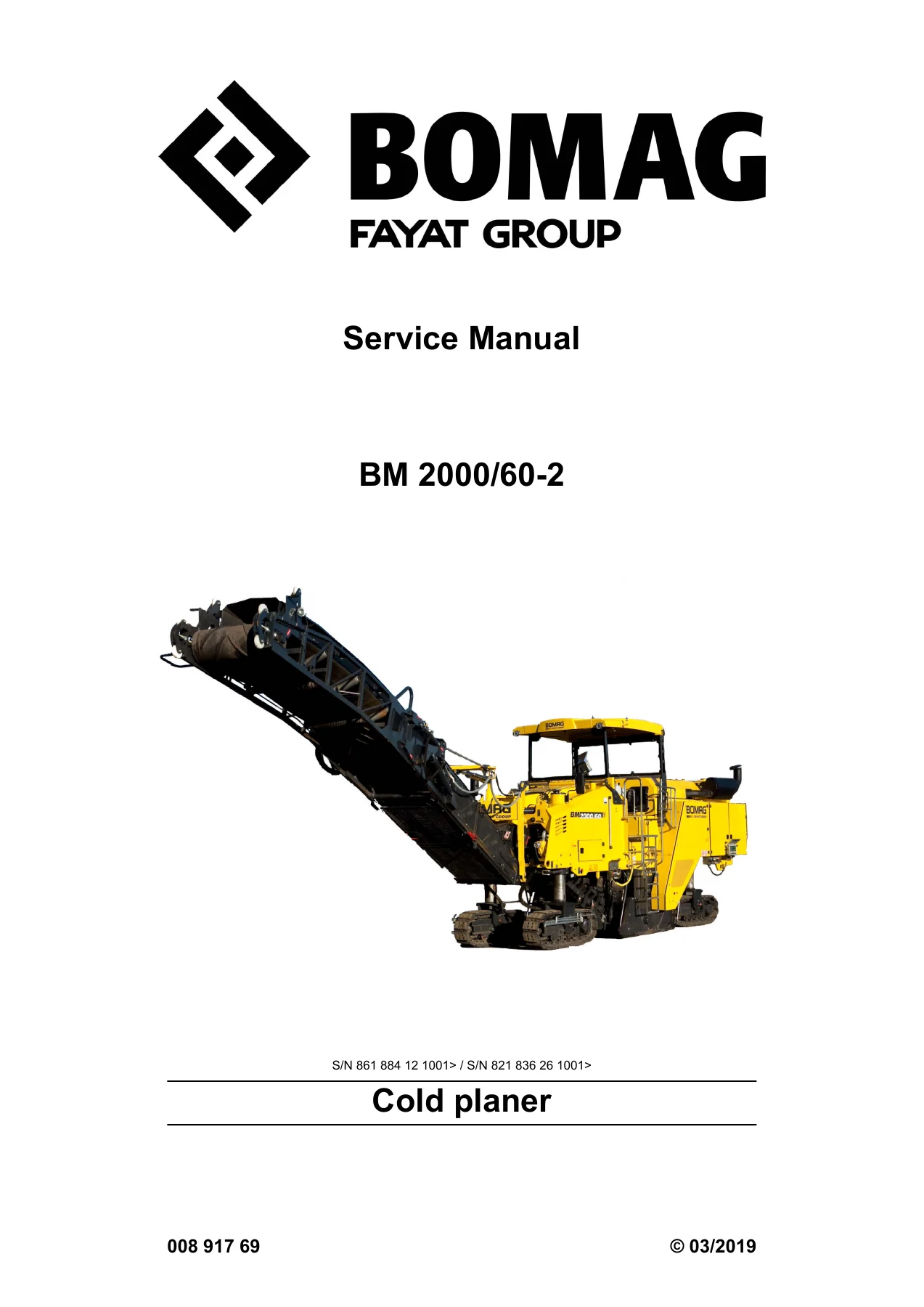
The BOMAG BM 2000/60-2 Cold Planer Service Manual 00891769 2019 is written for BOMAG customer service and professionally trained personnel who repair this cold planer in the workshop. It supports deinstallation, dismantling, assembly, installation, and component repair where tools and spare-parts supply make that work practical. The title page identifies the machine as a cold planer, prints document number 008 917 69 with the 03/2019 date, and lists serial ranges S/N 861 884 12 1001> and S/N 821 836 26 1001>. Intended use in the safety chapter is milling of asphalt or concrete road surfaces inside cordoned-off construction sites.
File Details
- Manual type: Service Manual
- Brand / model: BOMAG BM 2000/60-2 cold planer
- Language: English
- Page count: 794
- File format: PDF
- Document number: 008 917 69
- Date: 03/2019
- Serial ranges on cover: S/N 861 884 12 1001> / S/N 821 836 26 1001>
Machine identity and published data
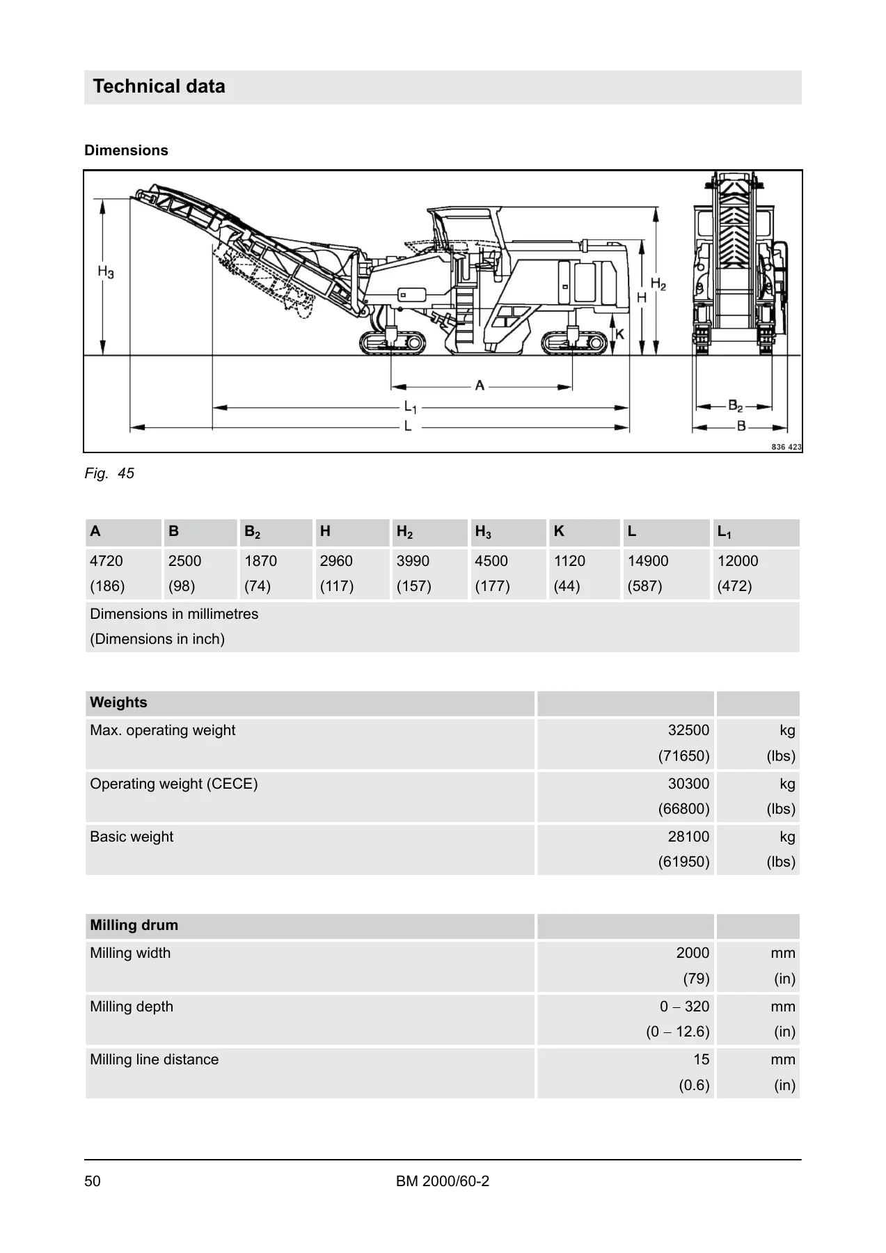
Technical data in this copy of the BOMAG BM 2000/60-2 Cold Planer Service Manual 00891769 2019 places the planer on a chain-type track drive and gives a milling width of 2000 mm (79 in), milling depth of 0–320 mm (0–12.6 in), milling line distance of 15 mm (0.6 in), cutting diameter of 1070 mm (42 in), 168 cutting tools, and drum rated speed of 108 min-1. Published weights are a maximum operating weight of 32500 kg (71650 lbs), operating weight (CECE) of 30300 kg (66800 lbs), and basic weight of 28100 kg (61950 lbs). Travel speed is 0–5 km/h (0–3 mph), working speed 0–40 m/min (0–131 ft/min), and maximum gradeability depending on soil is 18° / 32%.
The drive chapter specifies a fluid-cooled Deutz TCD 2015 V08 eight-cylinder engine rated 440 kW (600 hp) ISO 3046 at 1900 min-1. Later engine text describes a water-cooled V8 with cylinder banks at 90°, four-valve heads, turbocharger and intercooler, solenoid-valve electronic injection (MVS), internal exhaust-gas recirculation, and emission compliance stated as EPA/COM/Tier/stage III. Electrical system voltage is 24 V. Filling capacities listed include 1200 l (317 gal US) diesel, 3500 l (925 gal US) water, 45 l engine oil, 100 l coolant, and 230 l hydraulic oil HVLP 46.
Chapters Covered
- 1 General — Introduction; Concerning your safety; Signage; Maintenance and repair; Notes on repair; Preliminary remarks and safety notes; Preparations/concluding work
- 2 Technical data — Terms and basis of calculation; Fuels and lubricants (engine oil, fuel, coolant, hydraulic oil, gear oils, greases); List of fuels and lubricants
- 3 Overview of machine — Component overview electrics; Component overview hydraulics; Machine assemblies (engine, conveyor system, steering, radiator module, milling unit, milling drum, water system)
- 4 Electric systems — Basic principles (Deutsch DT/DTM connectors, clip-on technology, magnetic coil plug, Telemecanique switch); Operating consoles; Central electrics; Installation locations; Description of electrical components; Generator and generator repair; Electric starter and starter repair; Wiring looms; CAN BUS overview; Display (control elements, indicators, information/warnings/error messages); Service settings (hydraulics screen, engine screen, fault messages, advanced functions, configuration parameters, Check Input Output, machine states, CAN BUS settings); Fuse assignment; Starting the engine with jump leads; List of equipment; Inspection and maintenance work
- 5 Hydraulic system — Open and closed circuits; Swash plate principle for motor and pump; Hydraulic component and pump positions; Hoses; Description of hydraulic components (cylinders, travel motor, travel pump, working pump, fan motor A2FM32, conveyor belt pump, 4/3 way valve, pressure limiting valve, flow divider, main valve block, fan block, valve block for auxiliary control); Tests and adjustments including travel-pump check and adjustment; Inspection and maintenance work
- 6 Machine assemblies — Diesel engine; Conveyor system; Track chain drive and steering; Radiator module; Milling unit; Milling drum; Water system
- 7 Troubleshooting — Diesel engine (jump starting, engine malfunctions, Deutz DTC fault code list EMR3); Hydraulics (component table, axial piston motors and pumps, insufficient hydraulic power)
- 8 Special tools — Special tools, Deutz engine (TCD 2015)
- 9 Index
- Appendix A Circuit diagram
- Appendix B Hydraulic diagram
Taken together, those chapters give a technician a single path from safety and fluids through electrical and hydraulic architecture into the physical assemblies that cut, convey, steer, and cool the machine, then into fault-code and hydraulic-power diagnosis and the engine special-tool list. Circuit and hydraulic diagrams sit in the appendix rather than as standalone shop books.
Electrical service content
Chapter 4 of the BOMAG BM 2000/60-2 Cold Planer Service Manual 00891769 2019 starts with connector practice: Deutsch DT and DTM series, clip-on technology, magnetic coil plugs, and Telemecanique switches. It then maps operating consoles, central electrics, and installation locations before describing individual components. Generator and starter sections include repair sequences, not only identification. Wiring-loom and CAN BUS overviews sit ahead of the display chapter, which covers control elements, indicators, and information, warning, and error messages.
Service settings walk through starting the display, calling the hydraulics and engine screens, reading fault messages, opening advanced functions, working with configuration parameters, running Check Input Output, reviewing machine states, and adjusting CAN BUS settings. Fuse assignment covers safety notes, central electrics, and main fuses. Jump-lead starting is documented with polarity rules. A long equipment list tags operating devices by function, and electrical inspection work is scheduled at 250 and 1000 operating hours.
Hydraulic service content
The hydraulic chapter explains open versus closed circuits and the swash-plate principle on both motor and pump before locating components and pumps on the machine. Hose information is followed by component descriptions for hydraulic cylinders, the Bosch Rexroth A4VG travel pump and A6VE travel motor, the A10VO working pump, fan motor A2FM32, conveyor belt pump, 4/3 way valve, pressure limiting valve, flow divider, main valve block, fan block, and the auxiliary-control valve block. Published pump and motor figures include travel-pump high-pressure limitation of 380 bar and low-pressure limitation of 25 bar, conveyor-belt pump high-pressure limitation of 260 bar, and working-pump high-pressure limitation of 315 bar. Tests and adjustments include special tools plus checking and adjusting the travel pump. Hydraulic maintenance tables cover 10-hour and 1000-hour work.
Engine, milling drum, tracks, and water
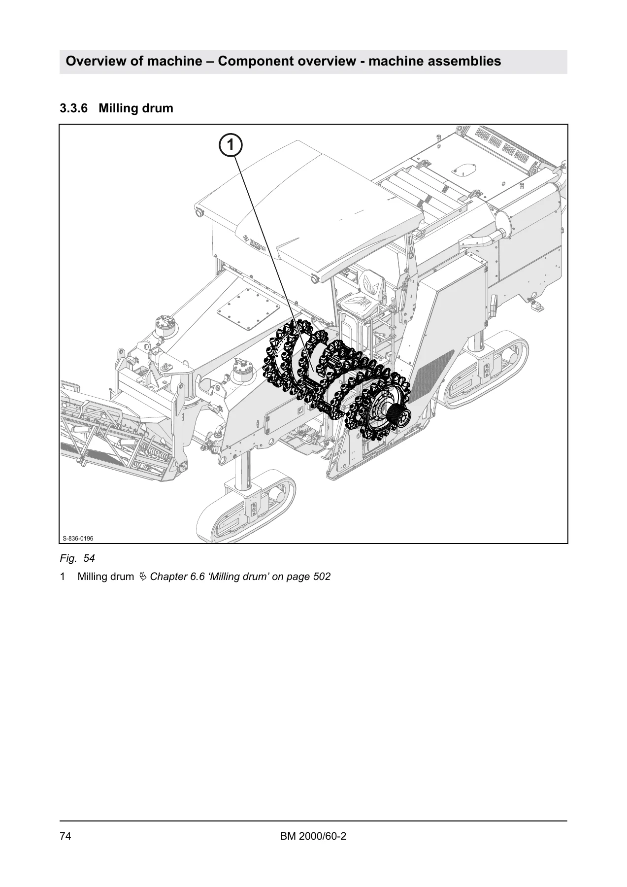
Machine-assembly chapters treat the Deutz TCD 2015 diesel as a serviceable unit, then move to the conveyor (loading belt 800 × 2400 mm, discharge belt 800 × 7600 mm), track-chain drive and steering with repair and inspection, the radiator module, the milling unit (milling box, door, side plates, hold-down, scrapers), the milling drum with repair and inspection, and the water spraying system. Track-chain dimensions are given as 1700 × 300 × 640 mm. Travel gear data names a Bonfiglioli 705 C 3 H unit with reduction ratio 1:80, nominal torque 6000 Nm, brake torque 180–220 Nm, and minimum brake release pressure 15 bar.
Fuels and lubricants specify Deutz DQC III-10 or DQC IV-10 engine oils, diesel to EN 590 / ASTM D975 Grade 1-D and 2-D / JIS K 2204 with sulphur limits, coolant mixing ratios from 35% to 50% protection agent, hydraulic oil HV 46 (HVLP per DIN 51524 part 3), optional ester-based biodegradable oil, gear oil ISO VG 220 for milling gear and drum support bearings, SAE 75W-90 for travel gear and transfer case, and the two grease specifications used on lubrication points and the milling-drum-drive clutch.
Diagnosis and special tools
Troubleshooting separates engine and hydraulic work. Engine coverage includes jump starting, malfunction tables, and the Deutz DTC fault code list for EMR3. Hydraulic troubleshooting includes a component table, axial-piston motor and pump fault paths, and a section on insufficient hydraulic power. Chapter 8 lists special tools for the Deutz TCD 2015, including base plates and crankshaft-seal assembly tools named in that chapter.
What this manual lets you do
With the BOMAG BM 2000/60-2 Cold Planer Service Manual 00891769 2019 on the bench, a trained technician can locate electrical modules and hydraulic blocks, work display service menus and configuration parameters, follow fuse maps, service the generator and starter, check and adjust the travel pump, repair track-chain drive and steering, service the milling unit and drum, maintain the conveyor and water system, and use EMR3 fault codes plus hydraulic-power checks when the machine will not produce expected travel or work power. Correct pressures, fluid grades, serial applicability, and torque or adjustment values from this book keep those jobs aligned with the published procedure instead of guesswork.
After payment you receive instant PDF delivery. There is no shipping wait. Open the file on a workshop PC, tablet, or phone and print the pages you need at the machine.

Reviews
There are no reviews yet.