★ TRUSTED BY 321,897+ PROFESSIONALS WORLDWIDE
🏢
Trusted Business
Verified & Licensed
🛡️
Virus Free Files
100% Safe Downloads
🔒
Secure Payment
SSL Protected
Instant Delivery
Available Immediately
Sale!

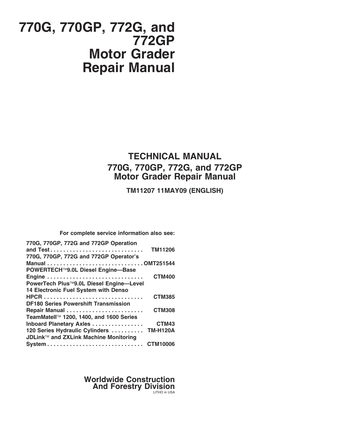
John Deere 770G 770GP 772G 772GP Motor Grader Repair Manual TM11207 PDF

Original price was: $34.95.Current price is: $19.95.

Complete factory-style repair manual (TM11207, 11MAY09) for John Deere 770G, 770GP, 772G, and 772GP Motor Graders, covering wheels, axles, transmission, engine, hydraulics, steering, brakes, operator’s station, and grading device service. Instant PDF download.

Instant PDF Download
Available immediately
💾
Save to Your Device
Download & keep forever
🛡️
Antivirus Scanned
100% virus-free
🌍
Trusted Worldwide
175,000+ customers

Description

John Deere 770G, 770GP, 772G, and 772GP Motor Grader Repair Manual TM11207 PDF

This is the complete John Deere 770G, 770GP, 772G, and 772GP Motor Grader Repair Manual TM11207, dated 11MAY09, written for technicians who service these grading machines in the field or in the shop. If you’re searching for a dependable 770G 770GP 772G 772GP Motor Grader Repair Manual, this technical manual walks through removal, installation, disassembly, assembly, and specification data for every major system on the machine, organized exactly as John Deere structured it for dealer technicians.

File Details

  • Manual type: Technical/Repair Manual (John Deere ILLUSTRUCTION Manual)
  • Brand/Models: John Deere 770G, 770GP, 772G, and 772GP Motor Graders
  • Document number: TM11207
  • Publication date: 11MAY09 (May 2009)
  • Language: English
  • Page count: 610 pages
  • File format: PDF, instant digital download

Chapters Covered

The 770G 770GP 772G 772GP Repair Manual is broken into numbered sections and groups covering the machine end to end:

IMAGES PREVIEW

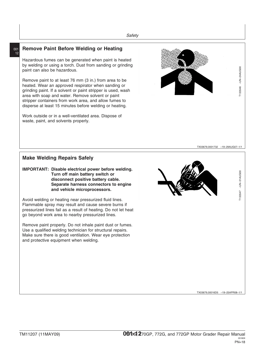
John Deere 770G 770GP 772G 772GP Motor Grader Repair Manual TM11207 PDF — PDF page 1 preview
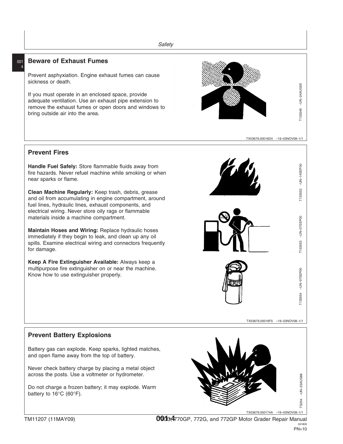
John Deere 770G 770GP 772G 772GP Motor Grader Repair Manual TM11207 PDF — PDF page 12 preview
John Deere 770G 770GP 772G 772GP Motor Grader Repair Manual TM11207 PDF — PDF page 20 preview

  • General Information — Safety, Torque Values
  • Section 01 — Wheels: Powered Wheels and Fasteners
  • Section 02 — Axles and Suspension Systems: Input Drive Shafts and U-Joints, Non-Powered Wheel Axles, Powered Wheel Axles, Axle Shafts/Bearings/Reduction Gears, Hydraulic System
  • Section 03 — Transmission: Removal and Installation, Hydraulic System
  • Section 04 — Engine: Removal and Installation (PowerTech Plus 9.0L / 6090 John Deere engine, Tier 3/Stage IIIA and Stage II)
  • Section 05 — Engine Auxiliary System: Cooling System, External Fuel Supply Systems
  • Section 07 — Torsional Isolator: Elements
  • Section 09 — Steering System: Power Steering, Hydraulic System
  • Section 10 — Service Brakes: Active Elements, Hydraulic System
  • Section 11 — Park Brake: Active Elements
  • Section 17 — Frame, Chassis or Supporting Structure: Frame Installation
  • Section 18 — Operator’s Station: Removal and Installation, Operator Enclosure, Pedal Assembly, Steering Tilt Console, Seat and Seat Belt, Heating and Air Conditioning
  • Section 19 — Sheet Metal and Styling: Grille and Grille Housing
  • Section 21 — Main Hydraulic System
  • Section 34 — Grading Device: Controls Linkage, Frames, Circle Gearbox, Hydraulic System
  • Section 42 — Ground Conditioning Tool: Frames
  • Section 99 — Dealer Fabricated Tools

Taken together, this gives a technician a full service path through the driveline, hydraulics, engine, operator’s station, and grading components of the 770G/770GP/772G/772GP line, with the diagnostic and repair depth needed to move from problem to fix without guessing at procedures.

What’s Inside

Each service group in this John Deere manual opens with the essential tools, service equipment, specifications, wear tolerances, and torque values needed before starting the job, then walks through the actual remove, disassemble, inspect, assemble, and install steps with numbered illustrations. Component-specific torque and weight specifications (for example, hub torque and hub weight callouts on the axle groups) are called out inline so a technician isn’t hunting through a separate spec sheet mid-repair. The manual also cross-references companion publications for the operator’s manual, the PowerTech 9.0L engine, the DF180 Series Powershift Transmission, TeamMate II inboard planetary axles, 120 Series hydraulic cylinders, and the JDLink/ZXLink monitoring system, so the scope here is specifically the grader’s own chassis, drivetrain, hydraulic, and structural systems.

Complete PDF Bookmark Tree

Complete Bookmarks

The complete bookmarks in the “John Deere 770G 770GP 772G 772GP Motor Grader Repair Manual TM11207 PDF” are as follows:

Contentsp. 3
General Informationp. 7
Safetyp. 9
Recognize Safety Informationp. 9
Follow Safety Instructionsp. 9
Operate Only If Qualifiedp. 10
Wear Protective Equipmentp. 10
Avoid Unauthorized Machine Modificationsp. 10
Inspect Machinep. 11
Stay Clear of Moving Partsp. 11
Avoid High-Pressure Oilsp. 11
Beware of Exhaust Fumesp. 12
Prevent Firesp. 12
Prevent Battery Explosionsp. 12
Handle Chemical Products Safelyp. 13
Dispose of Waste Properlyp. 13
Prepare for Emergenciesp. 13
Use Steps and Handholds Correctlyp. 14
Start Only From Operator's Seatp. 14
Use and Maintain Seat Beltp. 14
Prevent Unintended Machine Movementp. 15
Avoid Work Site Hazardsp. 15
Keep Riders Off Machinep. 16
Avoid Backover Accidentsp. 16
Avoid Machine Tip Overp. 17
Operating Or Traveling On Public Roadsp. 17
Inspect and Maintain ROPSp. 18
Add and Operate Attachments Safelyp. 18
Park And Prepare For Service Safelyp. 19
Service Cooling System Safelyp. 19
Remove Paint Before Welding or Heatingp. 20
Make Welding Repairs Safelyp. 20
Drive Metal Pins Safelyp. 21
Torque Valuesp. 23
Torque Valuep. 23
Metric Bolt and Cap Screwp. 23
Additional Metric Cap Screw Torque Valuesp. 24
Torque Valuep. 26
Unified Inch Bolt and Cap Screwp. 26
Service Recommendations for 37° Flare and 30° Cone Seat Connectorsp. 27
Service Recommendations for O-Ring Boss Fittingsp. 28
Service Recommendations For Flared Connections—Straight or Tapered Threadsp. 30
Service Recommendations For Flat Face O-Ring Seal Fittingsp. 31
Service Recommendationp. 33
O-Ring Face Seal Fittings with SAE Inch Hex Nut and Stud End for High Pressurep. 33
O-Ring Face Seal Fittings with Metric Hex Nut and Stud End for Standard Pressurep. 35
O-Ring Face Seal Fittings with Metric Hex Nut and Stud End for High Pressurep. 37
Service Recommendations for Metric Series Four Bolt Flange Fittingp. 39
Service Recommendations For Inch Series Four Bolt Flange Fittingsp. 40
Inch Series Four Bolt Flange Fitting For High Pressure Service Recommendationsp. 41
Service Recommendations For Non-Restricted Banjo (Adjustable) Fittingsp. 42
Service Recommendations For O-Ring Boss Fittings With Shoulderp. 44
Service Recommendationp. 47
Metric 24 O-Ring Seal DIN 20078p. 47
Wheelsp. 49
Powered Wheels and Fastenersp. 51
Wheel Remove and Installp. 51
Tire Remove and Installp. 52
Axles and Suspension Systemsp. 55
Input Drive Shafts and U-Jointsp. 57
Transmission-to-Rear Axle Drive Shaft Remove and Installp. 57
Transmission-to-Rear Axle Drive Shaft Disassemble and Assemblep. 58
Non-Powered Wheel Axlesp. 59
Front Wheel Hub and Spindle Remove and Install—Non 6WDp. 59
Front Wheel Hub and Spindle Disassemble and Assemble—Non 6WDp. 62
Front Axle Remove and Install—Non 6WDp. 65
Powered Wheel Axlesp. 69
Front Wheel Hub and Spindle Remove and Install—6WDp. 69
Front Wheel Hub and Spindle Disassemble and Assemble—6WDp. 73
Front Wheel Hub and Spindle Disassemble and Assemble with Steering Angle Sensor—6WDp. 79
6WD Drive Hub Disassemble and Assemblep. 86
Planetary Drive Disassemble and Assemblep. 88
Planetary Brake Disassemble and Assemblep. 92
6WD Bearings Remove and Installp. 97
6WD O-Ring Metal Face Seal Remove and Installp. 102
Front Axle Remove and Install—6WDp. 110
Axle Shafts, Bearings, and Reduction Gearsp. 117
TEAMMATE™ II 1400 Series Inboard Planetary Axle—Use CTM43p. 117
Rear Axle Remove and Installp. 117
Rear Axle Disassemble and Assemblep. 122
Tandem and Wheel Axle Assembly Remove and Installp. 123
Tandem Wheel Axle Assembly Remove and Installp. 126
Tandem Wheel Axle Assembly Disassemble and Assemblep. 128
Tandem Pivot Disassemble and Assemblep. 134
Final Drive Axle Remove and Installp. 138
Final Drive Axle Disassemble and Assemblep. 145
Brake Component Remove and Installp. 149
Planet Pinion Carrier Remove and Installp. 150
Tandem Drive Shaft Remove and Installp. 152
Drive Chain Remove and Installp. 157
Hydraulic Systemp. 161
6WD Pump Remove and Installp. 161
6WD Pump Disassemblep. 164
6WD Pump Assemblep. 182
6WD Charge Pump Remove and Installp. 202
6WD Engagement Manifold Remove and Installp. 202
Differential Lock Pump Remove and Installp. 205
6WD Motor Remove and Installp. 206
6WD Motor Disassemble and Assemblep. 208
Transmissionp. 213
Removal and Installationp. 215
DF180 Transmissionp. 215
Transmission Remove and Installp. 217
Hydraulic Systemp. 223
Transmission Charge Pump Remove and Installp. 223
Enginep. 225
Removal and Installationp. 227
PowerTech Plus™ 9.0L (6090) John Deere Engine—9.0L Tier 3/Stage IIIAp. 227
PowerTech Plus™ 9.0L (6090) John Deere Engine—9.0L Stage IIp. 227
Engine Remove and Install—9.0L Tier 3/Stage IIIAp. 228
Engine Remove and Install—9.0L Stage IIp. 237
Engine Auxiliary Systemp. 239
Cooling Systemp. 241
Fan Blade Remove and Installp. 241
Radiator Remove and Installp. 243
Hydraulic and Differential Oil Cooler Remove and Installp. 248
Transmission Oil Cooler Remove and Installp. 250
Fuel Cooler Remove and Install—9.0Lp. 253
Charge Air Cooler Remove and Installp. 254
External Fuel Supply Systemsp. 257
Fuel Tank Remove and Installp. 257
Fast Fill Fuel System Disassemble and Assemble—If Equippedp. 262
Torsional Isolatorp. 265
Elementsp. 267
Torsional Isolator Remove and Installp. 267
Steering Systemp. 269
Power Steeringp. 271
Toe-In Check and Adjustmentp. 271
Hydraulic Systemp. 273
Steering Wheel, Column, and Valve Remove and Install—Standard Controlsp. 273
Steering Wheel, Column, and Valve Remove and Install—EH Controlsp. 276
EH Controls Steering Canceling Valve Remove and Installp. 278
Steering Cylinder Remove and Installp. 280
Hydraulic Cylinder Disassemble and Assemblep. 283
Wheel Lean Cylinder Remove and Installp. 284
Secondary Steering Accumulator Remove and Install—If Equippedp. 289
Service Brakesp. 291
Active Elementsp. 293
Service Brake Repairp. 293
Hydraulic Systemp. 295
Service Brake Valve Remove and Installp. 295
Service Brake Bleedingp. 297
Brake Accumulator Remove and Installp. 298
Park Brakep. 301
Active Elementsp. 303
Park Brake Repairp. 303
Frame, Chassis or Supporting Structurep. 305
Frame Installationp. 307
Welding On Machinep. 307
Welding Repair of Major Structurep. 308
Separate Frames at Articulation Jointp. 309
Articulation Bearing Replacementp. 316
Operator's Stationp. 321
Removal and Installationp. 323
Cab Remove and Installp. 323
Cab Remove and Install—GP Machine Onlyp. 331
Operator Enclosurep. 339
Windowpanes Remove and Installp. 339
Cab Door Handle Remove and Installp. 340
Cab Door Latch Remove and Installp. 341
Rivet Nut Installationp. 343
Pedal Assemblyp. 347
Inching Pedal Remove and Installp. 347
Steering Tilt Consolep. 350
Steering Support Console Remove and Install—Standard Controlsp. 350
Steering Support Console Remove and Install—EH Controlsp. 352
Console Tilt Remove and Installp. 354
Steering Tilt Assembly Remove and Installp. 356
Seat and Seat Beltp. 357
Seat Remove and Installp. 357
Seat Belt Remove and Installp. 359
Armrest Remove and Installp. 361
Armrest Remove and Install—EH Controlsp. 362
Armrest Disassemble and Assemble—EH Controlsp. 364
Standard Seat Disassemble and Assemblep. 366
Deluxe Seat Disassemble and Assemblep. 368
Air Suspension Disassemble and Assemblep. 370
Heating and Air Conditioningp. 373
Refrigerant Cautions and Proper Handlingp. 373
Flush and Purge Air Conditioner Systemp. 375
R134a Refrigerant Oil Informationp. 380
R134a Refrigerant Recovery/Recycling and Charging Station Installation Procedurep. 382
R134a System Recoverp. 383
R134a System Evacuatep. 384
R134a System Chargep. 386
Expansion Valve Remove and Installp. 387
Freeze Control Switch Remove and Installp. 389
Air Conditioning High-Low Pressure Switch Remove and Installp. 391
Heater Control Valve Remove and Installp. 392
Heater Control Valve Leak Checkp. 393
Blower Motor Assembly Remove and Installp. 393
Compressor Remove and Install—6.8Lp. 394
Compressor Remove and Install—9.0Lp. 396
Condenser Remove and Installp. 398
Heater and Air Conditioner Remove and Installp. 400
Receiver-Dryer Remove and Installp. 405
Accumulator Remove and Installp. 406
Compressor Clutch Disassemble and Assemblep. 407
Compressor Manifold Inspectp. 408
Compressor Relief Valve Remove and Installp. 409
Sheet Metal and Stylingp. 411
Grille and Grille Housingp. 413
Grille Housing Remove and Installp. 413
Main Hydraulic Systemp. 417
Hydraulic Systemp. 419
Vacuum Pump Installationp. 419
Hydraulic Pump Remove and Installp. 419
Hydraulic Pump Disassemble and Assemblep. 422
Hydraulic System Manifold Remove and Installp. 428
Hydraulic System Manifold Disassemble and Assemblep. 430
Soft Start Valve Remove and Installp. 431
Soft Start Valve Disassemble and Assemblep. 434
Hydraulic Fan Pump Remove and Installp. 435
Hydraulic Fan Motor Remove and Installp. 436
Hydraulic Fan Valve Remove and Installp. 437
General Oil Cleanup Procedurep. 441
Hydraulic/Hydrostatic Component Failure Cleanup Procedurep. 444
Grading Devicep. 449
Controls Linkagep. 451
Control Linkage Remove and Installp. 451
Framesp. 453
NeverGrease™ Pin Jointsp. 453
Lift Arms Remove and Installp. 458
Saddle Locking Cylinder Remove and Installp. 462
Saddle Frame Remove and Installp. 465
Blade Pitch Frame Remove and Installp. 468
Draft and Circle Frame Remove and Installp. 472
Circle Adjustmentp. 476
Blade Side Shift Wear Inserts Remove and Installp. 481
Circle Gearboxp. 485
Circle Drive Gearbox Remove and Installp. 485
Circle Drive Gearbox Disassemble and Assemblep. 488
Circle Drive Gearbox (With Slip Clutch) Disassemble and Assemblep. 494
Hydraulic Systemp. 509
Grader Control Valve Remove and Installp. 509
Draft Frame Mount Grader Control Valve Remove and Install—EH Controlsp. 513
Cab Mount Grader Control Valve Remove and Install—EH Controlsp. 517
Grader Control Valve Disassemble and Assemblep. 520
Midmount Scarifier Valve Section Disassemble and Assemblep. 522
Midmount Scarifier Valve Section Disassemble and Assemble—EH Controlsp. 524
Blade Lift Valve Section Disassemble and Assemblep. 526
Blade Lift Valve Section Disassemble and Assemble—EH Controlsp. 528
Auxiliary (With Float) Valve Section Disassemble and Assemblep. 530
Auxiliary (Without Float) Valve Section Disassemble and Assemblep. 532
Auxiliary Valve Section Disassemble and Assemble—EH Controlsp. 534
Wheel Lean, Articulation, Circle Side Shift, Blade Pitch, and Blade Side Shift Valve Section Disassemble and Assemblep. 536
Wheel Lean, Articulation, Circle Side Shift, Blade Pitch, Blade Side Shift, and Steering Valve Section Disassemble and Assemble—EH Controlsp. 538
Circle Rotate Valve Section Disassemble and Assemblep. 540
Circle Rotate Valve Section Disassemble and Assemble—EH Controlsp. 542
Return Check Poppets Disassemble and Assemblep. 544
Rotate Motor Disassemble and Assemblep. 545
Rotary Manifold Remove and Installp. 547
Blade Lift, Blade Pitch, and Circle Side Shift Cylinders Remove and Installp. 550
Blade Side Shift Cylinder Remove and Installp. 552
Articulation Cylinders Remove and Installp. 555
Ground Conditioning Toolp. 559
Framesp. 561
NeverGrease™ Pin Jointsp. 561
Scarifier/Blade Remove and Installp. 565
Midmount Scarifier Remove and Installp. 567
Midmount Scarifier Cylinder Remove and Installp. 574
Ripper Remove and Installp. 576
Ripper Cylinders Remove and Installp. 579
Balderson™ Style Front Lift Group Remove and Installp. 581
Dealer Fabricated Toolsp. 583
Dealer Fabricated Toolsp. 585
DF1017—Axle Lift Eyep. 585
DF1057—Axle Adjusting Toolp. 586
DFRW20 Compressor Holding Fixturep. 587
DFRW103—Yoke Holding Tool1p. 588
DFT1101 Cab and ROPS Lift Bracketp. 589
DFT1151—Outboard Bearing Driverp. 590
DFT1152—Inboard Bearing Driverp. 591
DFT1153—Oil Seal Driverp. 591
DFT1225—Rolling Torque Measurement Toolp. 592
DFT1250 Lifting Bracketp. 593
DFT1282—King Pin Torque Adapterp. 594
DFT1308 Transmission Support Bracketp. 596
DFT1310—Cab Mount Control Valve Support Bracketp. 598
DFT1311—Extension for DFT1250p. 600
Page Numbersp. 3
Sectionp. 7
Group 001p. 9
1p. 9
2p. 10
3p. 11
4p. 12
5p. 13
6p. 14
7p. 15
8p. 16
9p. 17
10p. 18
11p. 19
12p. 20
13p. 21
14p. 22
Group 0003p. 23
1p. 23
2p. 24
3p. 25
4p. 26
5p. 27
6p. 28
7p. 29
8p. 30
9p. 31
10p. 32
11p. 33
12p. 34
13p. 35
14p. 36
15p. 37
16p. 38
17p. 39
18p. 40
19p. 41
20p. 42
21p. 43
22p. 44
23p. 45
24p. 46
25p. 47
26p. 48
27p. 49
28p. 50
Section 01p. 49
Group 0110p. 51
1p. 51
2p. 52
3p. 53
4p. 54
5p. 55
6p. 56
Section 02p. 55
Group 0225p. 57
1p. 57
2p. 58
Group 0230p. 59
1p. 59
2p. 60
3p. 61
4p. 62
5p. 63
6p. 64
7p. 65
8p. 66
9p. 67
10p. 68
Group 0240p. 69
1p. 69
2p. 70
3p. 71
4p. 72
5p. 73
6p. 74
7p. 75
8p. 76
9p. 77
10p. 78
11p. 79
12p. 80
13p. 81
14p. 82
15p. 83
16p. 84
17p. 85
18p. 86
19p. 87
20p. 88
21p. 89
22p. 90
23p. 91
24p. 92
25p. 93
26p. 94
27p. 95
28p. 96
29p. 97
30p. 98
31p. 99
32p. 100
33p. 101
34p. 102
35p. 103
36p. 104
37p. 105
38p. 106
39p. 107
40p. 108
41p. 109
42p. 110
43p. 111
44p. 112
45p. 113
46p. 114
47p. 115
48p. 116
Group 0250p. 117
1p. 117
2p. 118
3p. 119
4p. 120
5p. 121
6p. 122
7p. 123
8p. 124
9p. 125
10p. 126
11p. 127
12p. 128
13p. 129
14p. 130
15p. 131
16p. 132
17p. 133
18p. 134
19p. 135
20p. 136
21p. 137
22p. 138
23p. 139
24p. 140
25p. 141
26p. 142
27p. 143
28p. 144
29p. 145
30p. 146
31p. 147
32p. 148
33p. 149
34p. 150
35p. 151
36p. 152
37p. 153
38p. 154
39p. 155
40p. 156
41p. 157
42p. 158
43p. 159
44p. 160
Group 0260p. 161
1p. 161
2p. 162
3p. 163
4p. 164
5p. 165
6p. 166
7p. 167
8p. 168
9p. 169
10p. 170
11p. 171
12p. 172
13p. 173
14p. 174
15p. 175
16p. 176
17p. 177
18p. 178
19p. 179
20p. 180
21p. 181
22p. 182
23p. 183
24p. 184
25p. 185
26p. 186
27p. 187
28p. 188
29p. 189
30p. 190
31p. 191
32p. 192
33p. 193
34p. 194
35p. 195
36p. 196
37p. 197
38p. 198
39p. 199
40p. 200
41p. 201
42p. 202
43p. 203
44p. 204
45p. 205
46p. 206
47p. 207
48p. 208
49p. 209
50p. 210
51p. 211
52p. 212
53p. 213
54p. 214
Section 03p. 213
Group 0300p. 215
1p. 215
2p. 216
3p. 217
4p. 218
5p. 219
6p. 220
7p. 221
8p. 222
Group 0360p. 223
1p. 223
2p. 224
3p. 225
4p. 226
Section 04p. 225
Group 0400p. 227
1p. 227
2p. 228
3p. 229
4p. 230
5p. 231
6p. 232
7p. 233
8p. 234
9p. 235
10p. 236
11p. 237
12p. 238
13p. 239
14p. 240
Section 05p. 239
Group 0510p. 241
1p. 241
2p. 242
3p. 243
4p. 244
5p. 245
6p. 246
7p. 247
8p. 248
9p. 249
10p. 250
11p. 251
12p. 252
13p. 253
14p. 254
15p. 255
16p. 256
Group 0560p. 257
1p. 257
2p. 258
3p. 259
4p. 260
5p. 261
6p. 262
7p. 263
8p. 264
9p. 265
10p. 266
Section 07p. 265
Group 0752p. 267
1p. 267
2p. 268
3p. 269
4p. 270
Section 09p. 269
Group 0920p. 271
1p. 271
2p. 272
Group 0960p. 273
1p. 273
2p. 274
3p. 275
4p. 276
5p. 277
6p. 278
7p. 279
8p. 280
9p. 281
10p. 282
11p. 283
12p. 284
13p. 285
14p. 286
15p. 287
16p. 288
17p. 289
18p. 290
19p. 291
20p. 292
Section 10p. 291
Group 1011p. 293
1p. 293
2p. 294
Group 1060p. 295
1p. 295
2p. 296
3p. 297
4p. 298
5p. 299
6p. 300
7p. 301
8p. 302
Section 11p. 301
Group 1111p. 303
1p. 303
2p. 304
3p. 305
4p. 306
Section 17p. 305
Group 1740p. 307
1p. 307
2p. 308
3p. 309
4p. 310
5p. 311
6p. 312
7p. 313
8p. 314
9p. 315
10p. 316
11p. 317
12p. 318
13p. 319
14p. 320
15p. 321
16p. 322
Section 18p. 321
Group 1800p. 323
1p. 323
2p. 324
3p. 325
4p. 326
5p. 327
6p. 328
7p. 329
8p. 330
9p. 331
10p. 332
11p. 333
12p. 334
13p. 335
14p. 336
15p. 337
16p. 338
Group 1810p. 339
1p. 339
2p. 340
3p. 341
4p. 342
5p. 343
6p. 344
7p. 345
8p. 346
Group 1815p. 347
1p. 347
2p. 348
Group 1816p. 350
1p. 349
2p. 350
3p. 351
4p. 352
5p. 353
6p. 354
7p. 355
8p. 356
Group 1821p. 357
1p. 357
2p. 358
3p. 359
4p. 360
5p. 361
6p. 362
7p. 363
8p. 364
9p. 365
10p. 366
11p. 367
12p. 368
13p. 369
14p. 370
15p. 371
16p. 372
Group 1830p. 373
1p. 373
2p. 374
3p. 375
4p. 376
5p. 377
6p. 378
7p. 379
8p. 380
9p. 381
10p. 382
11p. 383
12p. 384
13p. 385
14p. 386
15p. 387
16p. 388
17p. 389
18p. 390
19p. 391
20p. 392
21p. 393
22p. 394
23p. 395
24p. 396
25p. 397
26p. 398
27p. 399
28p. 400
29p. 401
30p. 402
31p. 403
32p. 404
33p. 405
34p. 406
35p. 407
36p. 408
37p. 409
38p. 410
39p. 411
40p. 412
Section 19p. 411
Group 1921p. 413
1p. 413
2p. 414
3p. 415
4p. 416
5p. 417
6p. 418
Section 21p. 417
Group 2160p. 419
1p. 419
2p. 420
3p. 421
4p. 422
5p. 423
6p. 424
7p. 425
8p. 426
9p. 427
10p. 428
11p. 429
12p. 430
13p. 431
14p. 432
15p. 433
16p. 434
17p. 435
18p. 436
19p. 437
20p. 438
21p. 439
22p. 440
23p. 441
24p. 442
25p. 443
26p. 444
27p. 445
28p. 446
29p. 447
30p. 448
31p. 449
32p. 450
Section 34p. 449
Group 3415p. 451
1p. 451
2p. 452
Group 3440p. 453
1p. 453
2p. 454
3p. 455
4p. 456
5p. 457
6p. 458
7p. 459
8p. 460
9p. 461
10p. 462
11p. 463
12p. 464
13p. 465
14p. 466
15p. 467
16p. 468
17p. 469
18p. 470
19p. 471
20p. 472
21p. 473
22p. 474
23p. 475
24p. 476
25p. 477
26p. 478
27p. 479
28p. 480
29p. 481
30p. 482
31p. 483
32p. 484
Group 3450p. 485
1p. 485
2p. 486
3p. 487
4p. 488
5p. 489
6p. 490
7p. 491
8p. 492
9p. 493
10p. 494
11p. 495
12p. 496
13p. 497
14p. 498
15p. 499
16p. 500
17p. 501
18p. 502
19p. 503
20p. 504
21p. 505
22p. 506
23p. 507
24p. 508
Group 3460p. 509
1p. 509
2p. 510
3p. 511
4p. 512
5p. 513
6p. 514
7p. 515
8p. 516
9p. 517
10p. 518
11p. 519
12p. 520
13p. 521
14p. 522
15p. 523
16p. 524
17p. 525
18p. 526
19p. 527
20p. 528
21p. 529
22p. 530
23p. 531
24p. 532
25p. 533
26p. 534
27p. 535
28p. 536
29p. 537
30p. 538
31p. 539
32p. 540
33p. 541
34p. 542
35p. 543
36p. 544
37p. 545
38p. 546
39p. 547
40p. 548
41p. 549
42p. 550
43p. 551
44p. 552
45p. 553
46p. 554
47p. 555
48p. 556
49p. 557
50p. 558
51p. 559
52p. 560
Section 42p. 559
Group 4240p. 561
1p. 561
2p. 562
3p. 563
4p. 564
5p. 565
6p. 566
7p. 567
8p. 568
9p. 569
10p. 570
11p. 571
12p. 572
13p. 573
14p. 574
15p. 575
16p. 576
17p. 577
18p. 578
19p. 579
20p. 580
21p. 581
22p. 582
23p. 583
24p. 584
Section 99p. 583
Group 9900p. 585
1p. 585
2p. 586
3p. 587
4p. 588
5p. 589
6p. 590
7p. 591
8p. 592
9p. 593
10p. 594
11p. 595
12p. 596
13p. 597
14p. 598
15p. 599
16p. 600

Why Technicians Rely on This Manual

With this John Deere 770G 770GP 772G 772GP Motor Grader Repair Manual, a shop can diagnose and repair wheel and axle issues, transmission and driveline faults, engine removal and installation, steering and brake hydraulic problems, operator’s station repairs, and grading circle/moldboard hydraulics using the exact torque values, clearances, and procedures John Deere published for this equipment — instead of relying on guesswork or generic references. Getting the correct specification matters here: undertightened or overtightened hub nuts, incorrect torque on structural fasteners, or missed hydraulic system steps can lead to premature wear or unsafe operation, and this manual is written to prevent exactly that. The file downloads instantly after purchase as a PDF, works on any laptop, tablet, or phone, needs no shipping or waiting, and can be printed for shop use whenever a page is needed at the bench.
Reviews

There are no reviews yet.

Be the first to review “John Deere 770G 770GP 772G 772GP Motor Grader Repair Manual TM11207 PDF”

What Our Customers Say

★★★★★ Live reviews from customers
Loading customer reviews...
0
    0
    Your Cart
    Your cart is emptyReturn to Shop
    🛒
    Recently Purchased
    🕒 verified order