★ TRUSTED BY 321,897+ PROFESSIONALS WORLDWIDE
🏒
Trusted Business
Verified & Licensed
πŸ›‘οΈ
Virus Free Files
100% Safe Downloads
πŸ”’
Secure Payment
SSL Protected
⚑
Instant Delivery
Available Immediately
Sale!

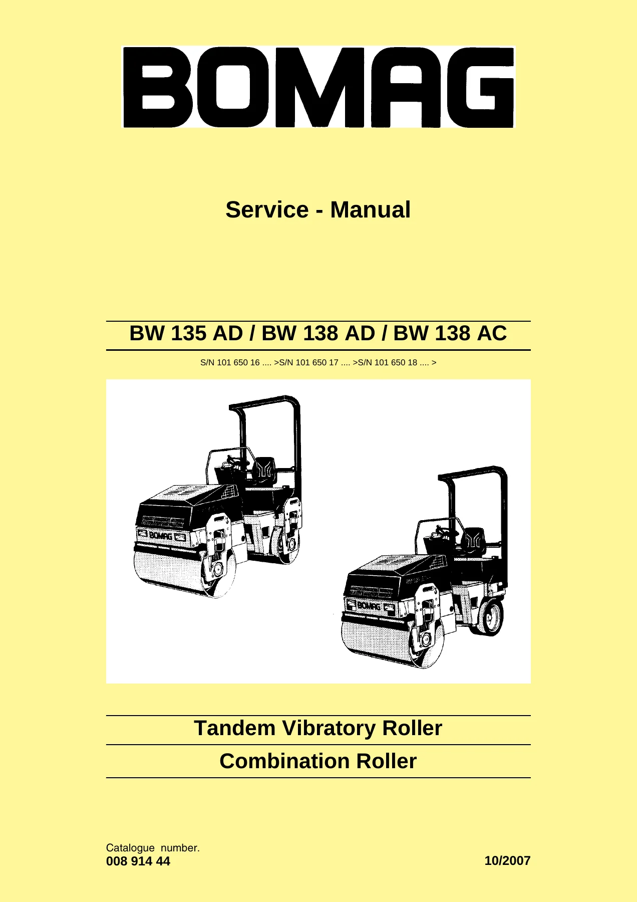
BOMAG BW 135 AD BW 138 AD BW 138 AC Tandem Vibratory Roller Service Manual – 2007

Original price was: $34.95.Current price is: $19.95.

478-page BOMAG service manual for BW 135 AD, BW 138 AD and BW 138 AC tandem vibratory and combination rollers. Full hydraulic, electrical, drum and articulated joint repair coverage, plus supplier documentation for the travel pump, drum drive and wheel drive motors.

⚑
Instant PDF Download
Available immediately
πŸ’Ύ
Save to Your Device
Download & keep forever
πŸ›‘οΈ
Antivirus Scanned
100% virus-free
🌍
Trusted Worldwide
175,000+ customers

Description

BOMAG BW 135 AD BW 138 AD BW 138 AC Tandem Vibratory Roller Service Manual – 2007

This BOMAG BW 135 AD BW 138 AD BW 138 AC Tandem Vibratory Roller Service Manual is the complete workshop-level repair and maintenance reference for these three tandem roller variants, covering both the AD (dual drum) and AC (combination drum and rubber wheel) configurations. Spanning 478 pages, it gives mechanics and fleet technicians the full scope of procedures, specifications, test values, diagnostic flowcharts and component-level repair instructions needed to keep these compact tandem rollers working correctly. The manual is organised into thirteen chapters that move from general repair practice through to full supplier documentation and circuit diagrams, so everything from a routine oil change to a travel pump neutral adjustment is covered in one document.

File Details

  • Manual type: Service Manual
  • Brand: BOMAG
  • Models covered: BW 135 AD, BW 138 AD, BW 138 AC
  • Document number: 00891444
  • Year of publication: 2007
  • Language: English
  • Page count: 478
  • File format: PDF

Chapters Covered

  • General – Introduction, safety regulations, general repair instructions and tightening torques
  • Maintenance – General notes, fuels and lubricants, running-in instructions, maintenance chart
  • Technical data – Dimensions, weights, travel characteristics, engine data, pump and motor data
  • Tests and adjustments – Special tools, rotation speeds, pressure tests in travel and vibration circuits, neutral position of the travel pump (Sauer pump), leakage rate of the vibration motor, steering circuit pressure test
  • Trouble shooting – General notes and full trouble shooting diagram for travel, vibration, steering and brake systems
  • Fundamental electrics – Circuit diagrams, terminal designations, current, voltage, resistance, series and parallel circuits, Ohm’s law, diodes, relays, fuses, batteries, three-phase generator, electric starter, Telemecanique switch, inductive proximity switches, angle sensor, plug connectors
  • Special tools, electrics – Measuring equipment and special tools for electrical diagnostics
  • Machine related electrics – Vibration module and Module A68 seat contact monitoring
  • Flushing and bleeding – Special tools, flushing schematics for front and rear drum drives, wheel drive motors and vibration circuit, bleeding the travel circuit
  • Drum – Special tools, repair overview, removing and installing the drum, dismantling and assembling the drum
  • Oscillating articulated joint – Special tools, repair overview, removing, installing, dismantling and assembling the oscillating articulated joint
  • Suppliers documentation – Travel pump A10VG28 (Bosch Rexroth), travel pump series 42 (Sauer), drum drive MK05/08/11/18 (Poclain), wheel drive MS/MSE 02…18 (Poclain)
  • Circuit diagrams – Wiring diagrams and hydraulic diagrams

The document is far more than a routine maintenance schedule. It is a structured service manual that breaks each major assembly down into removal, dismantling, inspection, reassembly and adjustment steps, with tightening torques, nominal values and test pressures stated throughout. The trouble shooting chapter alone uses a flowchart format that leads a technician through each system – travel, vibration, steering and brake – from a symptom to a specific component or adjustment. That means an experienced mechanic can diagnose a fault without guesswork and then follow the repair instructions to correct it.

IMAGES PREVIEW

BOMAG BW 135 AD BW 138 AD BW 138 AC Tandem Vibratory Roller Service Manual - 2007 β€” PDF page 1 preview
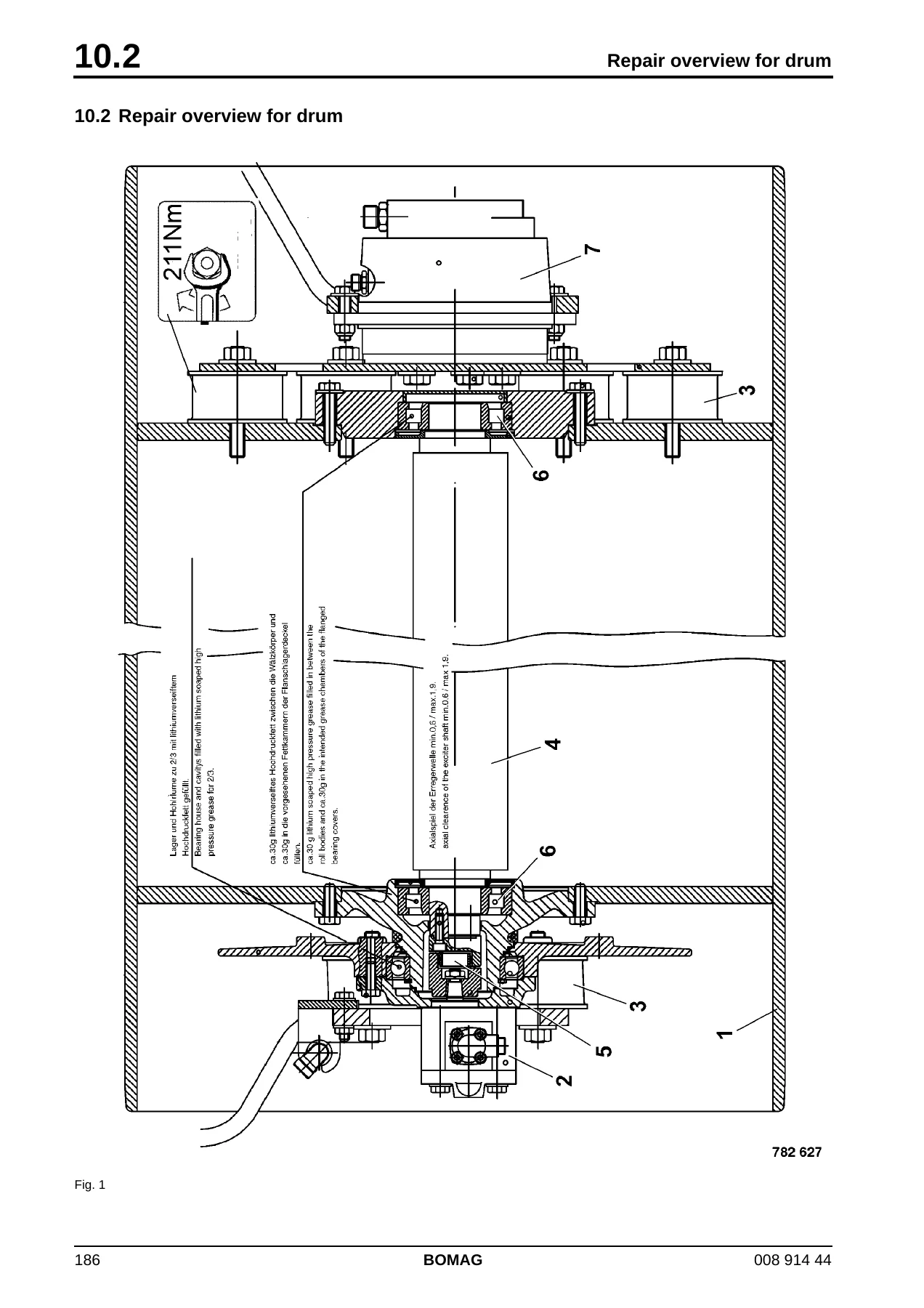
BOMAG BW 135 AD BW 138 AD BW 138 AC Tandem Vibratory Roller Service Manual - 2007 β€” PDF page 186 preview
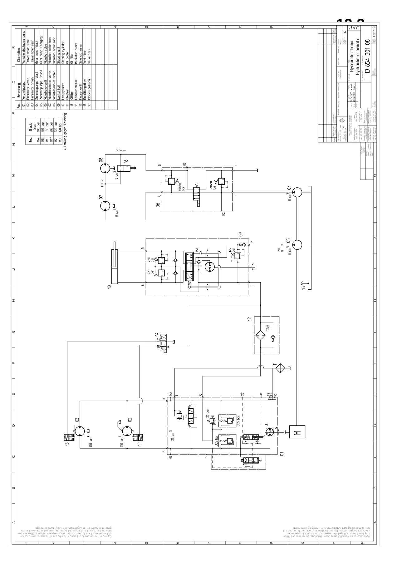
BOMAG BW 135 AD BW 138 AD BW 138 AC Tandem Vibratory Roller Service Manual - 2007 β€” PDF page 467 preview

The hydraulics coverage is especially thorough. The manual includes pressure test procedures for the travel circuit, vibration circuit and steering circuit, along with the exact nominal values a technician should expect to see at operating temperature. There is also a dedicated flushing and bleeding chapter with schematics for the front drum drive, rear drum drive, rear wheel drive motors and the vibration circuit – a critical procedure after any component replacement to prevent contamination from damaging the rebuilt system. The supplier documentation section extends this by reproducing the full repair instructions for the Bosch Rexroth A10VG28 travel pump, the Sauer series 42 travel pump, the Poclain MK05/08/11/18 drum drive motors and the Poclain MS/MSE wheel drive motors, including exploded views, disassembly sequences, reassembly torque values and adjustment procedures. This alone makes the manual valuable for anyone working on the hydrostatic drive components of these rollers.

On the electrical side, the manual starts from fundamental electrics and works up to machine-specific circuits. It explains terminal designations, how to read circuit diagrams, voltage and resistance measurement, diodes, relays, fuses, batteries, three-phase generators, starters, inductive proximity switches and the angle sensor used on these machines. The wiring diagrams for the BW 135 AD, BW 138 AD and BW 138 AC are included, along with hydraulic diagrams, so circuit-level fault finding is fully supported. The machine-related electrics chapter covers the vibration module and the Module A68 seat contact monitoring system, including its pin assignments, inputs, outputs, emergency operation and the French and standard option behaviours.

Because the manual covers three distinct machines, it is worth noting that some sections apply only to specific models or configurations. The BW 135 AD uses a Bosch Rexroth A10VG28 travel pump, while the BW 138 AD and BW 138 AC use a Sauer series 42 travel pump. Vibration frequency, amplitude and engine data are tabulated separately for each model. The BW 138 AC is the combination roller, so it has rubber wheels at the rear instead of a second drum, and the wheel drive motor documentation applies to that configuration. The manual flags these differences where they matter, but a technician should always confirm the model and serial number before ordering parts or applying a specific pressure value.

The opening chapter sets out the safety regulations, general repair instructions and tightening torque tables that apply across the whole machine. It covers metric screws in strength classes 8.8, 10.9 and 12.9, metric fine thread, UNC and UNF threads, wheel nuts, and screws treated with anti-seize paste. This is the reference data a mechanic needs when reassembling any part of the roller, and having it in the same document as the repair procedures removes the need to hunt through separate tables.

For day-to-day maintenance, the manual includes the full maintenance chart with intervals from every 10 operating hours through to every 5000 operating hours, covering engine oil checks, hydraulic oil level, fuel level, water level in the sprinkler system, emulsion level, greasing the articulated joint, cleaning cooling fins and hydraulic oil cooler, adjusting scrapers, servicing the battery, draining sludge from the fuel tank, changing engine oil and filters, checking valve clearance and V-belt tension, and replacing toothed belts. It also specifies the fuels and lubricants to use, including engine oil viscosity by ambient temperature, hydraulic oil HV 46, and biodegradable hydraulic oil options.

Complete PDF Bookmark Tree

Complete Bookmarks

The complete bookmarks in the β€œBOMAG BW 135 AD BW 138 AD BW 138 AC Tandem Vibratory Roller Service Manual – 2007” are as follows:

BW 135 AD / BW 138 AD / BW 138 ACp. 1
S/N 101 650 16 …. >S/N 101 650 17 …. >S/N 101 650 18 …. >p. 1
Tandem Vibratory Rollerp. 1
Combination Rollerp. 1
1 Generalp. 5
1.1 Introductionp. 6
Safety regulationsp. 7
Important notesp. 7
Generalp. 7
Precautions and codes of conduct for welding workp. 7
Old oilsp. 8
Hydraulicsp. 8
Fuelsp. 9
Hot fuelsp. 9
Synthetic rubberp. 9
Poisonous substancesp. 9
Enginep. 9
Batteryp. 9
Special safety regulationsp. 10
General repair instructionsp. 11
Generalp. 11
Electricsp. 11
Batteryp. 12
Hydraulic systemp. 13
Fuel hosesp. 14
Fig. 1p. 14
Gaskets and mating surfacesp. 14
Fig. 2p. 14
Fig. 3p. 15
Feather keys and keywaysp. 15
Fig. 4p. 15
Ball and roller bearingsp. 16
Fig. 5p. 16
Fig. 6p. 16
Screws and nutsp. 17
Fig. 7 Identification of screwsp. 17
Fig. 8 Identification of nutsp. 18
Fig. 9 Identification of nuts in clock systemp. 18
Tightening torquesp. 19
2 Maintenancep. 23
2.1 General notes on maintenancep. 24
Notes on the fuel systemp. 24
Notes on the engine performancep. 24
Notes on the hydraulic systemp. 24
2.2 Fuels and lubricantsp. 25
Engine oilp. 25
Fig. 10p. 25
Oil viscosityp. 25
Regular lubrication oil changesp. 25
Oil qualityp. 25
Lubrication oil change intervalsp. 25
Lubrication oil quality classesp. 25
Fuelsp. 26
Winter fuelp. 26
Mineral oil based hydraulic oilp. 26
Bio-degradable hydraulic oilp. 26
Lubrication greasep. 26
2.3 Table of fuels and lubricantsp. 27
2.4 Running-in instructionsp. 28
2.5 Maintenance chartp. 29
3 Technical datap. 31
Technical datap. 32
Fig. 11p. 32
Fig. 12p. 34
Noise valuep. 38
Vibration valuep. 38
4 Tests and adjustmentsp. 39
4.1 Special tools, tests and adjustmentsp. 40
Fig. 1p. 40
Fig. 2p. 40
Fig. 3p. 40
Fig. 4p. 40
Fig. 5p. 41
Fig. 6p. 41
Fig. 7p. 41
Fig. 8p. 41
Fig. 9p. 42
Fig. 10p. 42
Fig. 11p. 42
Fig. 12p. 42
Fig. 13p. 43
Fig. 14p. 43
4.2 Checking the rotation speedsp. 44
Fig. 1p. 44
Check the engine speedp. 44
Fig. 2p. 44
Checking the exciter shaft speedp. 45
Fig. 3p. 45
Fig. 4p. 45
4.3 Pressure tests in the travel circuitp. 46
Fig. 1p. 46
Fig. 2p. 46
Fig. 3p. 46
4.4 Checking / adjusting the neutral positions of the travel pump (Sauer pump)p. 48
Fig. 1p. 48
Fig. 2p. 48
Fig. 3p. 48
Fig. 4p. 49
Fig. 5p. 49
Fig. 6p. 49
Fig. 7p. 49
Fig. 8p. 50
4.5 Pressure tests in the vibration circuitp. 51
Fig. 1p. 51
Fig. 2p. 51
Fig. 3p. 51
4.6 Checking the leakage rate of the vibration motorp. 52
Fig. 1p. 52
Fig. 2p. 52
4.7 Pressure test in steering circuitp. 53
Fig. 1p. 53
Fig. 2p. 53
Fig. 3p. 53
5 Trouble shootingp. 55
Generalp. 56
General notes on trouble shooting in hydraulic systemsp. 56
Important points for trouble shooting and fault rectificationp. 56
5.2 Trouble shooting diagramp. 57
6 Fundamental electricsp. 71
6.1 Understanding circuit diagramsp. 72
Fig. 4 Table of contentsp. 72
Fig. 5 Function groupsp. 73
Fig. 6 Current pathsp. 74
Fig. 7 List of componentsp. 74
Fig. 8 Graphic symbolp. 75
Fig. 9 Graphic symbolp. 75
6.2 Terminal designationsp. 76
6.3 Current and voltagep. 80
Generalp. 80
Voltagep. 80
Fig. 1p. 80
Fig. 2p. 80
Currentp. 81
Fig. 3 Circuitp. 81
Types of currentp. 81
Fig. 1 Direct current (D.C.)p. 81
Fig. 2 Alternating current (A.C.)p. 81
Fig. 3 Pulsating direct currentp. 81
Fig. 4 PWMp. 82
Fig. 5 CANp. 83
6.4 Resistancep. 84
Resistance and voltage dropp. 84
Fig. 1 Various size resistorsp. 84
Fig. 2 Potentiometer, infinitely adjustable resistorp. 84
Unnecessary resistancesp. 84
Fig. 1 Screw-type terminalsp. 84
Fig. 2 Spring clampsp. 84
Fig. 3p. 85
Fig. 4 Balistol oilp. 85
Fig. 5p. 85
6.5 Series / parallel connectionp. 86
Fig. 1 Series connectionp. 86
Fig. 2p. 86
Fig. 3 Parallel connectionp. 87
Fig. 4p. 87
6.6 Ohm's lawp. 88
Fig. 1p. 88
6.7 Electrical energyp. 88
Fig. 1p. 88
6.8 Formula diagramp. 89
Fig. 1 Formula diagramp. 89
6.9 Metrologyp. 90
Test lampsp. 90
Fig. 1 Test lampp. 90
Fig. 2 Diode test lampp. 90
Multimeterp. 90
Fig. 1 Multimeterp. 90
Fig. 2 Voltage measurementp. 91
Fig. 3 Current measurementp. 91
Clip-on measuring instrumentp. 91
Fig. 1 Clip-on measuring instrumentp. 91
Magnet testerp. 92
Fig. 1 Magnet testerp. 92
6.10 Diodes, relays, fusesp. 92
Diodesp. 92
Fig. 1p. 92
Fig. 2 Marking of the cathodep. 92
Fig. 3 Diode circuitryp. 93
Fig. 4 LEDp. 93
Relaysp. 94
Fig. 1 Relaysp. 94
Fig. 2 Relay circuitryp. 94
Fusesp. 94
Fig. 1p. 94
6.11 Batteriesp. 95
Fig. 1p. 95
Fig. 2p. 95
Fig. 3 Reading the acid levelp. 96
Fig. 4 Battery and generator testerp. 96
Fig. 5 Charge conditionp. 97
6.12 Three-phase generatorp. 98
Generalp. 98
Fig. 6 Rotor with claw polesp. 98
Fig. 7 Stator with 3 windingsp. 98
Fig. 8 3-phase currentp. 99
Fig. 9 Regulator with diode plate and rectifier diodesp. 100
Checking the generatorp. 100
Fig. 10 Connections on the three-phase alternator (exemplary design)p. 101
Fig. 11 Rotorp. 102
Fig. 12 Statorp. 102
Fig. 13p. 103
Fig. 14p. 103
Fig. 15p. 104
Fig. 16p. 104
Fig. 17p. 104
Fig. 18p. 104
6.13 Electric starterp. 106
Fig. 1 Electric starterp. 106
Fig. 2 Switching position during engagementp. 107
Fig. 3 Switching position during startingp. 107
6.14 Telemecanique switchp. 109
Fig. 1 Terminal designationsp. 109
Fig. 2 Disassemblyp. 110
Fig. 3 Folding down the switch blockp. 110
Fig. 4 Pulling out the front elementp. 110
Fig. 5 Assemblyp. 111
Fig. 6 Observe the marks.p. 111
Fig. 7 Assemble the switch blockp. 111
6.15 Inductive proximity switchesp. 112
Fig. 8p. 112
Fig. 9 PNP circuitryp. 112
Fig. 10 NPN circuitryp. 112
Fig. 11p. 112
Fig. 12 Circuit diagram, making contactp. 113
6.16 Angle sensor with current outputp. 113
Fig. 1 Sensorp. 113
Fig. 2 Connection diagramp. 114
6.17 Plug connectorsp. 114
6.18 Deutsch plug, series DT and DTMp. 115
Generalp. 115
Fig. 3 Crimp connectionsp. 115
DT Seriesp. 115
Fig. 1 DT plug connectionp. 115
Fig. 2 DT Seriesp. 115
Fig. 3 Sectional drawingp. 115
Fig. 4p. 116
Fig. 5p. 117
Fig. 1 DTM plug connectionp. 118
Fig. 2 DTM Seriesp. 118
Fig. 3 Sectional drawingp. 118
Fig. 4p. 119
Fig. 5p. 120
6.19 Plugs and terminals in spring clamping technologyp. 121
Generalp. 121
Fig. 1p. 121
Fig. 2 That's how it worksp. 121
Fig. 3 Connecting clampp. 121
Fig. 4 That's how it worksp. 122
Fig. 5 Test adapterp. 122
Fig. 6 That's how it worksp. 123
Fig. 7 X-COM plug with measuring cablep. 123
Fig. 8 X-COM plug plugged onto the series clampp. 123
7 Special tools, electricsp. 125
7.1 Special tools, electricsp. 126
Fig. 9p. 126
Fig. 10p. 126
Fig. 11p. 126
Fig. 12p. 126
Fig. 13p. 127
Fig. 14p. 127
Fig. 15p. 127
Fig. 16p. 128
Fig. 17p. 128
Fig. 18p. 128
Fig. 19p. 128
Fig. 20p. 129
Fig. 21p. 129
Fig. 22p. 129
Fig. 23p. 129
Fig. 24p. 130
Fig. 25p. 130
Fig. 26p. 130
Fig. 27p. 130
Fig. 28p. 131
Fig. 29p. 131
Fig. 30p. 131
Fig. 31p. 131
Fig. 32p. 132
Fig. 33p. 132
Fig. 34p. 132
Fig. 35p. 132
Fig. 36p. 133
Fig. 37p. 133
Fig. 38p. 133
Fig. 39p. 133
Fig. 40p. 134
Fig. 41p. 134
8 Machine related electricsp. 135
8.1 Vibration modulep. 137
8.2 Module A68p. 141
9 Flushing and bleedingp. 155
9.1 Special tools for flushingp. 156
Fig. 1p. 156
1. Filling and filtering unit with oil bagp. 156
2. Filter elementp. 156
Fig. 2p. 156
3. Flushing filter (S connection)p. 156
4. Filter element 1mp. 156
5. Flushing hose 20S – 25S (2 pieces)p. 156
6. Screw socket R1β€œ – 25S (2 pieces)p. 156
Fig. 3p. 156
7. Flushing filter (L connection)p. 156
8. Filter elementp. 156
9. Flushing hose 15L (2 pieces)p. 156
10. Screw socket R3/4β€œ — 15L (2 pieces)p. 156
Fig. 4p. 156
11. SAE-flange 1β€œ – 20Sp. 156
12. O-ringp. 156
Fig. 5p. 157
13. Flanged plate 1β€œ – 25Sp. 157
14. O-ringp. 157
Fig. 6p. 157
15. Reducing fitting 18L – 15Lp. 157
Fig. 7p. 157
16. Reducing fitting 25S – 20Sp. 157
Fig. 8p. 157
17. Reducing fitting 20S – 16Sp. 157
Fig. 9p. 158
18. Connecting socket 15Lp. 158
Fig. 10p. 158
19. Connecting socket 18Lp. 158
Fig. 11p. 158
20. Connecting socket 16Sp. 158
Fig. 12p. 158
21. Connecting fitting 20Sp. 158
Fig. 13p. 159
22. Connecting fitting 25Sp. 159
Fig. 14p. 159
23. Angular fitting 18Lp. 159
Fig. 15p. 159
24. Elbow fitting 16Lp. 159
Fig. 16p. 159
25. Elbow 20Sp. 159
Fig. 17p. 160
26. Elbow 25Sp. 160
Fig. 18p. 160
27. Pipe connection 16S – 16Sp. 160
Fig. 19p. 160
28. Connecting hose 15Lp. 160
9.2 Flushing – generalp. 161
Changing a componentp. 161
Chips (abrasion) in the oilp. 161
Open and clean all components in the oil circuit, replace if necessary.p. 161
Clean all high pressure hoses in the oil circuit, replace if necessary.p. 161
If abrasion is found in the travel circuit you should also flush the vibration circuit.p. 161
If abrasion is found in the vibration circuit you should also flush the travel circuit.p. 161
Before flushingp. 161
Fig. 1p. 161
Change the hydraulic oil filter element (1).p. 161
Fig. 2p. 161
Filter the tank content with the filling and filtering unit and pump it into the oil bag.p. 161
Mark all hoses and disconnect them from the hydraulic oil tank.p. 161
Clean the oil tank thoroughly from inside, if necessary remove the complete tank cover.p. 161
Reconnect all hoses.p. 161
Fill the hydraulic oil tank again with the filling and filtering unit.p. 161
Bleedingp. 161
Fig. 3p. 161
Always bleed closed hydraulic circuits if lines had been removed or connected.p. 161
Servicing the flushing filter kitp. 162
Fig. 4p. 162
Replace the filter element of the flushing filter when the red control pin of the contamination indicator is pressed out during the filtering process.p. 162
Clean hoses and connections and store the flushing kit in a clean and protected environment.p. 162
Flushing schematic for front drum drive
1 Travel pumpp. 163
2 Pipe joint (tool)p. 163
3 Reducing fitting (tool)p. 163
4 Connecting union (tool)p. 163
5 Rear drum drive motorp. 163
6 Flushing hose (tool) 20S – 25Sp. 163
7 Screw socket (tool) R1" – 25Sp. 163
8 Flushing filter 1m (tool)p. 163
9 Front drum drive motorp. 163
10 Connecting union (tool)p. 163
11 Elbow union (tool)p. 163
12 Connecting union (tool)p. 163
13 Reducing fitting (tool)p. 163
14 High pressure hosep. 163
15 Flushing hose (tool) 20S – 25Sp. 163
9.4 Flushing the front drum drivep. 164
Fig. 1p. 164
1. Disconnect the high pressure hose (14) from the travel pump (port B) and connect it with the flushing hose (6) flushing filter inlet "IN" (see chapter "Flushing schematic for front drum drive").p. 164
2. Connect the flushing hose (15) flushing filter outlet "OUT" to the high pressure port B on the travel pump.p. 164
Fig. 2p. 164
3. Take the drum drive motor out of the hydraulic circuit by joining the hoses together.p. 164
Fig. 3p. 165
Fig. 4p. 165
4. Block the drums with suitable chocks.p. 165
Fig. 5p. 165
Fig. 6p. 165
5. Start the engine and shift the travel lever to travel direction forward.p. 165
6. Perform the flushing process at various engine speeds for approx. 10 minutes.p. 165
7. Shut down the engine.p. 165
8. Reconnect the high pressure hoses to the drum drive motor.p. 165
Fig. 7p. 166
9. Jack up the front of the machine, so that the drum can rotate freely.p. 166
10. Secure the rear drum with chocks .p. 166
Fig. 8p. 166
Fig. 9p. 166
11. Start the engine, run it with maximum speed and shift the travel lever to travel direction forward.p. 166
12. Run the flushing procedure for approx. 10 minutes. During this process keep changing the pump flow by shifting the travel lever several times between full and halve reverse travel.p. 166
13. Shut down the engine.p. 166
14. Remove the flushing filter and reconnect the high pressure lines.p. 166
15. After completing the bleeding process circulate the tank content with the filling and filtering unit for another 15 minutes.p. 166
Fig. 10p. 167
16. Check the hydraulic oil level in the tank, fill up if necessary.p. 167
17. Check all connections for leaks with the engine running (visual inspection).p. 167
18. Perform a test drive, load the travel system in forward and reverse, e.g. by driving uphill or starting on a gradient.p. 167
19. Check all ports and connections for leak tightness (visual inspection).p. 167
Flushing schematic for rear drum drive system
1 Connecting union (tool)p. 168
2 Reducing fitting (tool)p. 168
3 Pipe joint (tool)p. 168
4 Rear drum drive motorp. 168
5 Flushing hose 20S – 25S (tool)p. 168
6 Screw socket (tool) R1" – 25Sp. 168
7 Flushing filter (tool)p. 168
8 Front drum drive motorp. 168
9 Connecting union (tool)p. 168
10 Reducing fitting (tool)p. 168
11 Elbow union (tool)p. 168
12 Connecting union (tool)p. 168
13 Travel pumpp. 168
14 High pressure hosep. 168
15 Flushing hose 20S – 25S (tool)p. 168
9.6 Flushing the rear drum drivep. 169
Fig. 1p. 169
1. Disconnect the high pressure hose (14) from the travel pump (port B) and connect it with the flushing hose (5) flushing filter inlet "IN" (see chapter "Flushing schematic for rear drum drive").p. 169
2. Connect the flushing hose (15) flushing filter outlet "OUT" to the high pressure port B on the travel pump.p. 169
Fig. 2p. 169
3. Take the drum drive motor out of the hydraulic circuit by joining the hoses together.p. 169
Fig. 3p. 170
Fig. 4p. 170
4. Block the drums with suitable chocks.p. 170
Fig. 5p. 170
Fig. 6p. 170
5. Start the engine and shift the travel lever to travel direction forward.p. 170
6. Perform the flushing process at various engine speeds for approx. 10 minutes.p. 170
7. Shut down the engine.p. 170
8. Reconnect the high pressure hoses to the drum drive motor.p. 170
Fig. 7p. 171
9. Jack up the rear of the machine, so that the drum can rotate freely.p. 171
10. Secure the front drum with chocks .p. 171
Fig. 8p. 171
Fig. 9p. 171
11. Start the engine, run it with maximum speed and shift the travel lever to travel direction forward.p. 171
12. Run the flushing procedure for approx. 10 minutes. During this process keep changing the pump flow by shifting the travel lever several times between full and halve reverse travel.p. 171
13. Shut down the engine.p. 171
14. Remove the flushing filter and reconnect the high pressure lines.p. 171
15. After completing the bleeding process circulate the tank content with the filling and filtering unit for another 15 minutes.p. 171
Fig. 10p. 172
16. Check the hydraulic oil level in the tank, fill up if necessary.p. 172
17. Check all connections for leaks with the engine running (visual inspection).p. 172
18. Perform a test drive, load the travel system in forward and reverse, e.g. by driving uphill or starting on a gradient.p. 172
19. Check all ports and connections for leak tightness (visual inspection).p. 172
Flushing schematic, rear wheel drive motors
1 Connecting union (tool)p. 173
2 Reducing fitting (tool)p. 173
3 Pipe joint (tool)p. 173
4 Rear wheel drive motorsp. 173
5 Flushing hose 20S – 25S (tool)p. 173
6 Screw socket (tool) R1" – 25Sp. 173
7 Flushing filter 1m (tool)p. 173
8 Front drum drive motorp. 173
9 Connecting union (tool)p. 173
10 Reducing fitting (tool)p. 173
11 Elbow union (tool)p. 173
12 Connecting union (tool)p. 173
13 Travel pumpp. 173
14 High pressure hosep. 173
15 Flushing hose 20S – 25S (tool)p. 173
9.8 Flushing the rear wheel drivep. 174
Fig. 1p. 174
1. Disconnect the high pressure hose (14) from the travel pump (port B) and connect it with the flushing hose (6) flushing filter inlet "IN" (see chapter "Flushing schematic for wheel drive motors").p. 174
2. Connect the flushing hose (15) flushing filter outlet "OUT" to the high pressure port B on the travel pump.p. 174
Fig. 2p. 174
3. Take the wheel drive motors (4) out of the hydraulic circuit and join the hoses together.p. 174
Fig. 3p. 175
Fig. 4p. 175
4. Block drum and wheels with suitable chocks .p. 175
Fig. 5p. 175
Fig. 6p. 175
5. Start the engine and shift the travel lever to travel direction forward.p. 175
6. Perform the flushing process at various engine speeds for approx. 10 minutes.p. 175
7. Shut down the engine.p. 175
8. Reconnect the high pressure hoses to the wheel drive motors.p. 175
Fig. 7p. 176
9. Jack up the rear of the machine, so that the rubber wheels can rotate freely.p. 176
10. Secure the front drum with chocks .p. 176
Fig. 8p. 176
Fig. 9p. 176
11. Start the engine, run it with maximum speed and shift the travel lever to travel direction forward.p. 176
12. Run the flushing procedure for approx. 10 minutes. During this process keep changing the pump flow by shifting the travel lever several times between full and halve reverse travel.p. 176
13. Shut down the engine.p. 176
14. Remove the flushing filter and reconnect the high pressure lines.p. 176
15. After completing the bleeding process circulate the tank content with the filling and filtering unit for another 15 minutes.p. 176
Fig. 10p. 177
16. Check the hydraulic oil level in the tank, fill up if necessary.p. 177
17. Check all connections for leaks with the engine running (visual inspection).p. 177
18. Perform a test drive, load the travel system in forward and reverse, e.g. by driving uphill or starting on a gradient.p. 177
19. Check all ports and connections for leak tightness (visual inspection).p. 177
Flushing schematic for vibration drive
1 Screw fitting 3/4β€œ – 15L (tool)p. 178
2 Flushing hose (tool)p. 178
3 Vibration valvep. 178
4 Vibration motor, rear (only AD-machine)p. 178
5 Vibration pumpp. 178
6 Hydraulic oil tankp. 178
7 Front vibration motorp. 178
8 Connecting union (tool)p. 178
9 Flushing filter (tool)p. 178
10 Hydraulic hosep. 178
11 Flushing hose (tool)p. 178
9.10 Flushing the vibration circuitp. 179
Fig. 1p. 179
1. Disconnect the hydraulic hose (10) from the vibration valve (port T) and connect it with the flushing hose (2) flushing filter inlet "OUT" (see chapter "Flushing schematic for vibration circuit").p. 179
2. Connect flushing hose (11) flushing filter inlet "IN" with the vibration valve (port T).p. 179
Fig. 2p. 179
3. Unscrew the fastening screws for the vibration motors and pull both motors (5 and 7) out of the coupling.p. 179
Fig. 3p. 180
4. Start the engine and run it with maximum speed.p. 180
5. Flush the circuit for approx. 10 minutes, thereby switch the vibration on and off at intervals of approx. 30 seconds.p. 180
6. Shut down the engine.p. 180
7. Remove the flushing filter and reinstall the vibration motors.p. 180
Fig. 4p. 180
8. Check the hydraulic oil level in the tank, fill up if necessary.p. 180
9. Test drive.p. 180
10. Check all ports and connections for leak tightness (visual inspection).p. 180
9.11 Bleeding the travel circuitp. 181
Fig. 1p. 181
1. Secure the drums with chocks .p. 181
Fig. 2p. 181
2. Actuate the emergency stop switch.p. 181
Fig. 3p. 181
3. Install a pressure test hose each to the high pressure test ports.p. 181
4. Install a pressure test hose to the charge pressure test port.p. 181
5. Hold the open ends of the pressure test hoses (Fig. 3) into a container.p. 181
6. Operate the starter motor for approx. 30 seconds. Wait one minute and repeat this procedure, until oil starts to run out from the pressure test hoses.p. 181
7. Remove the pressure test hoses.p. 181
Fig. 4p. 182
8. Unlock the emergency stop switchp. 182
Fig. 5p. 182
9. Connect a 60 bar pressure gauge to the charge pressure test port (Fig. 5) and run the engine max. 15 seconds at idle speed.p. 182
10. Pause for approx. 30 seconds and keep repeating this procedure, until the gauge shows a constant charge pressure reading.p. 182
Fig. 6p. 182
11. Start the engine.p. 182
12. Shift the travel lever (Fig. 6) approx. 1/3 to forward direction.p. 182
13. After approx. 1 to 2 minutes shut down the engine for a minute.p. 182
14. After a waiting time of approx. 1 minute keep repeating this procedure, until the indicated charge pressure drops directly to zero when shutting down the engine.p. 182
10 Drump. 183
10.1 Special toolsp. 184
Fig. 1p. 184
1. Bell to change the rubber buffersp. 184
Fig. 2p. 184
2. Lifting device for exciter unitp. 184
10.2 Repair overview for drump. 186
Fig. 1p. 186
1 Drump. 187
2 Vibration motorp. 187
3 Rubber bufferp. 187
4 Vibrator shaftp. 187
5 Couplingp. 187
6 Vibration bearingsp. 187
7 Drum drive motorp. 187
10.3 Removing and installing the drump. 188
Removing the drump. 188
Fig. 1p. 188
1. Jack the the machine up (Fig. 1) and support it safely, so that the rubber buffers on the drive disc are unloaded.p. 188
Fig. 2p. 188
2. Open flap 1 (Fig. 2).p. 188
3. Unscrew the hexagon screws (2) to remove the scrapers (3).p. 188
Fig. 3p. 188
4. Disassemble the bracket 1 (Fig. 3).p. 188
Fig. 4p. 189
5. Mark the hydraulic hoses and disconnect them from the vibration motor ports.p. 189
6. Close the connections with plugs.p. 189
7. Unscrew the nuts 1 (Fig. 4).p. 189
8. Unscrew the screws and remove the support (3).p. 189
Fig. 5p. 189
9. Disassemble the bracket 1 (Fig. 5).p. 189
10. Mark and disassemble hydraulic hoses (2) and pipes (3) from the drum drive motor.p. 189
11. Close the connections with plugs.p. 189
Fig. 6p. 189
12. Take the brake releasing device 1 (Fig. 6) out of the access steps.p. 189
Fig. 7p. 189
13. Remove the protection plug 6 (Fig. 7).p. 189
14. Place the brake releasing device (1) across the travel motor housing (2) and turn the screw (3) into the tapped bore (4), until it bottoms.p. 189
15. Screw the nut (5) down and tighten it approx. 1 to 2 turns.p. 189
Fig. 8p. 190
16. Unscrew the fastening screws 1 (Fig. 8) and roll the drum with travel motor and support leg forward out from the machine.p. 190
Installing the drump. 190
Fig. 9p. 190
17. Examine all rubber buffers for wear, replace if necessary.p. 190
Fig. 10p. 190
Fig. 11p. 190
18. Check the hydraulic oil level (Fig. 11), top up if necessary.p. 190
19. Perform a test drive, check function of travel system, vibration and water sprinkling system.p. 190
20. Check all connections and fittings for leak tightness.p. 190
10.4 Dismantling the drump. 191
Removing the drum drive motorp. 191
Fig. 1p. 191
1. Remove the brake releasing device 1 (Fig. 1) from the drum drive motor.p. 191
1. Attach the lifting tackle to the support leg (2).p. 191
2. Unscrew the fastening nuts (3) and separate the drive disc with travel motor and support leg from the drum.p. 191
Fig. 2p. 191
3. Remove the support leg 1 (Fig. 2) from the drum drive motor.p. 191
Fig. 3p. 191
4. Examine all rubber buffers (Fig. 3) for wear, replace if necessary.p. 191
Fig. 4p. 192
5. Unscrew the screws 1 (Fig. 4) and lift the drive disc (2) with intermediate ring (3) off the drum drive motor (4).p. 192
Remove the vibration motorp. 192
Fig. 5p. 192
1. Remove the vibration motor 1 (Fig. 5).p. 192
2. Check rubber buffers (2) for wear, replace if necessary.p. 192
Fig. 6p. 192
3. Remove the elastic coupling 1 (Fig. 6).p. 192
4. Unscrew nut (2) and pull the coupling hub (3) off with a puller.p. 192
5. Remove feather key (4).p. 192
Fig. 7p. 192
6. Unscrew both fastening screws 1 (Fig. 7) and separate the vibration motor (2) from the flange (3).p. 192
Disassembling the bearing coverp. 193
Fig. 8p. 193
1. Remove the circlip (Fig. 8) from the bearing housing.p. 193
Fig. 9p. 193
2. Press the bearing cover (Fig. 9) off the bearing housing with forcing screws.p. 193
Fig. 10p. 193
3. Knock the grooved ball bearing 1 (Fig. 10) out of the bearing cover (3).p. 193
4. Remove the Nilos ring (2).p. 193
Disassembling the exciter shaftp. 194
Fig. 11p. 194
1. Unscrew the fastening screws 1 (Fig. 11) for the bearing housing.p. 194
2. Remove the elastic coupling, check for wear, replace if necessary.p. 194
Fig. 12p. 194
3. Pick up the lifting device 1 (Fig. 12) with a crane and slide it over the exciter shaft.p. 194
4. Force the bearing housing out of the drum using forcing screws.p. 194
Fig. 13p. 194
5. Pull the exciter shaft (Fig. 13)out of the drum with a special tool.p. 194
Dismantling the exciter shaftp. 195
Fig. 14p. 195
1. Take the bearing housing (Fig. 14) off the exciter shaft.p. 195
Fig. 15p. 195
2. Knock the cylinder roller bearing (Fig. 15) out of the bearing housing.p. 195
Fig. 16p. 195
3. Pull coupling hub 1 (Fig. 16) off the exciter shaft.p. 195
Fig. 17p. 195
4. Pull inner bearing race 1 (Fig. 17) off both sides of the exciter shaft.p. 195
5. Remove seal ring (2) from both ends of the exciter shaft.p. 195
Removing the coverp. 196
Fig. 18p. 196
1. Unscrew the fastening screws (Fig. 18) from the drum.p. 196
2. Knock the cover with the exciter shaft out from the vibration drive side.p. 196
Fig. 19p. 196
3. Remove the cover (Fig. 19).p. 196
Fig. 20p. 196
4. Knock the cylinder roller bearing (Fig. 20) out of the bearing housing.p. 196
10.5 Assembling the drump. 197
Installing the bearing coverp. 197
Fig. 1p. 197
1. Press the new bearing (Fig. 2) down to full contact.p. 197
2. Fill approx. 30g of lithium saponified high pressure grease into the gap between the roller drums and another 30 g into the grease chamber of the bearing cover.p. 197
Fig. 2p. 197
3. Attach the locking cap (Fig. 2).p. 197
Fig. 3p. 197
4. Assemble the bearing cover (Fig. 3).p. 197
Assembling the exciter shaftp. 198
Fig. 4p. 198
5. Install the seal ring 2 (Fig. 4) on both ends of the exciter shaft.p. 198
6. Heat inner bearing races (1) up to approx. 80 ˚C and slide them on the exciter shaft from both ends.p. 198
Fig. 5p. 198
7. Install coupling hub 1 (Fig. 5).p. 198
Fig. 6p. 198
8. Knock the new bearing 1 (Fig. 6) into the bearing housing until it bottoms.p. 198
9. Fill approx. 30g of lithium saponified high pressure grease into the gap between the roller drums and another 30 g into the grease chamber of the bearing housing.p. 198
Fig. 7p. 198
10. Slide the bearing housing over the exciter shaft (Fig. 7).p. 198
Installing the exciter shaftp. 199
Fig. 8p. 199
11. Slide the special tool (Fig. 8)over the exciter shaft and insert it carefully into the opposite bearing.p. 199
Fig. 9p. 199
12. Fasten the bearing housing with screws 1 (Fig. 9).p. 199
13. Insert the elastic coupling into the coupling hub.p. 199
Measuring the end floatp. 199
Fig. 10p. 199
14. Screw the eye bolt (Fig. 10) into the exciter shaft bore to measure the end float.p. 199
15. Push the exciter shaft into the bearing housing against the end stop.p. 199
Fig. 11p. 200
16. Measure the distance between coupling and front face of bearing housing (Fig. 11).p. 200
Fig. 12p. 200
17. Pull the exciter shaft out of the flange against the stop (Fig. 12).p. 200
Fig. 13p. 200
18. Measure the distance between coupling and front face of bearing housing again (Fig. 13).p. 200
Assembling the bearing platep. 200
Fig. 14p. 200
19. Install Nilos ring 2 (Fig. 14).p. 200
20. Press the new bearing (1) into the bearing plate (3) until it bottoms and fill it to 2/3 with lithium saponified high pressure grease.p. 200
Fig. 15p. 201
21. Knock the bearing plate into the bearing housing using a drift punch (Fig. 15).p. 201
Fig. 16p. 201
22. Snap the circlip into the groove in the bearing housing (Fig. 16).p. 201
Installing the vibration motorp. 201
Fig. 17p. 201
23. Fasten the vibration motor 2 (Fig. 17) to the flange (3) with fastening screws (1).p. 201
Fig. 18p. 201
24. Insert the feather key 4 (Fig. 18).p. 201
25. Slide on coupling hub (3) and tighten nut (2) with 55 Nm.p. 201
26. Assemble the elastic coupling (1).p. 201
Fig. 19p. 202
27. Install the vibration motor 1 (Fig. 19).p. 202
28. If necessary fasten new rubber buffers (2) with 300 Nm.p. 202
Installing the drum drive motorp. 202
Fig. 20p. 202
29. If necessary fasten new rubber buffers with 300 Nm (Fig. 20).p. 202
Fig. 21p. 202
30. Use screws 1 (Fig. 21) and washers to connect the drum drive motor (4) to the drive disc (2) and the intermediate ring (3).p. 202
Fig. 22p. 202
31. Assemble the support leg 1 (Fig. 22) with the drum drive motor.p. 202
32. Attach the lifting tackle to the completely assembled unit.p. 202
Fig. 23p. 203
33. Attach the brake releasing device 1 (Fig. 23).p. 203
34. Assemble the drum drive motor with drive disc and support leg (2) to the drum.p. 203
35. Attach the drive disc to the rubber buffers and tighten the nuts (3) with 300 Nm.p. 203
11 Oscillating articulated jointp. 205
11.1 Special tools, oscillating articulated joint (BW100/120 family)p. 206
Fig. 1p. 206
1. Extraction ring for taper roller bearingp. 206
Repair overview Oscillating articulated joint
2 Tensioning nutp. 208
3 Oscillation axlep. 208
4 Bearing housingp. 208
5 Carrierp. 208
6 Bearing blockp. 208
7 Cylinder eye for steering cylinderp. 208
11.3 Removing and installing the oscillating articulated jointp. 210
Fig. 1p. 210
1. Support the front and rear frames of the machine safely with jacks (Fig. 1).p. 210
2. Disconnect the hydraulic hoses from the steering cylinder ports. Close the connections with plugs.p. 210
Fig. 2p. 210
3. Remove the split pin form the steering cylinder bearing bolt 1 (Fig. 2) and knock out the bolt.p. 210
4. Take off supporting discs (2).p. 210
5. Attach lifting tackle to the articulated joint.p. 210
6. Unscrew fastening screws (3 and 4), washers and nuts (5) and remove the articulated joint with the steering cylinder.p. 210
Fig. 3p. 210
7. Remove the split pin form the steering cylinder bearing bolt 1 (Fig. 3) and knock out the bolt.p. 210
8. Take off supporting discs (2).p. 210
Fig. 4p. 211
Fig. 5p. 211
11.4 Dismantling the oscillating articulated jointp. 212
Fig. 1p. 212
1. Disassemble bearing block 1 (Fig. 1) from both sides.p. 212
Fig. 2p. 212
2. Remove circlip 1 (Fig. 2) and backing disc (2).p. 212
Fig. 3p. 212
3. Pull both bearing blocks from the rocker bearing journals (Fig. 3).p. 212
Fig. 4p. 213
4. Take sealing rings 1 (Fig. 4) and supporting discs (2) out of the bearing blocks or off the shaft journals.p. 213
Fig. 5p. 213
5. Unscrew the fastening screws (Fig. 5) and remove the cylinder eye.p. 213
Fig. 6p. 213
6. Remove circlip 2 (Fig. 6) and backing disc (3).p. 213
7. Knock the rocker bearing (4) out of the bearing block (1).p. 213
Fig. 7p. 213
8. Knock the rocker bearing 1 (Fig. 7) out of the cylinder eye (2).p. 213
Fig. 8p. 214
9. Press the cross member 1 (Fig. 8) off the axle journal (2).p. 214
10. Take the seal rings (3) out of the housing at top and bottom.p. 214
Fig. 9p. 214
11. Loosen the clamping nut 1 (Fig. 9) with the tightening ring and remove it from the housing together with the Belleville spring (2).p. 214
12. Pull the oscillation axle (3) out of the housing. If the oscillation axle is tight knock it carefully out of the housing with a plastic hammer.p. 214
Fig. 10p. 214
13. Take out taper roller bearing 1 (Fig. 10) and knock the outer bearing races (2 and 4) out of the bearing housing (3).p. 214
Fig. 11p. 214
14. Separate the taper roller bearing 3 (Fig. 11) from the oscillation axle (1) and remove the supporting disc (2).p. 214
11.5 Assembling the oscillating articulated jointp. 215
Fig. 1p. 215
1. Slide the supporting disc 2 (Fig. 1) over the oscillation axle (1) and fit the new taper roller bearing (3).p. 215
2. Fill the taper roller bearing with lithium saponified high pressure grease.p. 215
Fig. 2p. 215
3. Knock the new outer bearing race into the bearing housing (Fig. 2).p. 215
Fig. 3p. 215
4. Turn the bearing housing upside down.p. 215
5. Press in the outer bearing race 1 (Fig. 3).p. 215
Fig. 4p. 216
6. Insert the oscillation axle 1 (Fig. 4) with taper roller bearing into bearing housing (2).p. 216
Fig. 5p. 216
7. Grease the new taper roller bearing 1 (Fig. 5) with lithium saponified high pressure grease and install.p. 216
8. Insert the Belleville spring (2) with arched area pointing inward.p. 216
9. Install the new tensioning nut (3) with the large outer diameter pointing inward.p. 216
Fig. 6p. 216
10. Tighten the tensioning nut with the tightening ring (Fig. 6), therebyp. 216
Fig. 7p. 216
11. measure the depth with a vernier calliper 1 (Fig. 7) through the bore in the tensioning nut (2).p. 216
12. If necessary tighten the tensioning nut until the nominal value is reached.p. 216
Fig. 8p. 217
13. Secure the tensioning nut with two prick-punch locks opposite each other (Fig. 8).p. 217
Fig. 9p. 217
14. Insert the seal ring 1 (Fig. 9) into the groove in the bearing housing.p. 217
Fig. 10p. 217
15. Insert two threaded bars 1 (Fig. 10) M16 x 200 into the oscillating axle.p. 217
Fig. 11p. 217
16. Knock the rocker bearing 1 (Fig. 11) into the cylinder eye (2).p. 217
Fig. 12p. 218
17. Heat the cross member 2 (Fig. 12) up to approx. 80 ˚C.p. 218
18. Mount the cylinder eye (1) with the four outer screws to the cross member (2).p. 218
Fig. 13p. 218
19. Attach the cross-member 2 (Fig. 13) to the oscillating axle, unscrew the threaded rods (1) from the oscillating axle and pull the cross-member with screws (3) tightly against the oscillating axle. Then allow the cross member to cool down.p. 218
Fig. 14p. 218
20. Tighten the fastening screws (Fig. 14).p. 218
Fig. 15p. 218
21. Slide the sealing rings 1 (Fig. 15) and the supporting discs (2) over both bearing journals.p. 218
Fig. 16p. 219
22. Assemble circlips 1 (Fig. 16) and supporting discs (2) in both bearing blocks.p. 219
23. Knock the new rocker bearings (3) until they bottom.p. 219
Fig. 17p. 219
24. Knock both bearing blocks 1 (Fig. 17) onto the bearing journals.p. 219
Fig. 18p. 219
25. Assemble circlip 1 (Fig. 18) with supporting disc (2) and check for correct fit.p. 219
Fig. 19p. 219
26. Fasten the bearing covers 1 (Fig. 19) on both sides with screws.p. 219
27. Lubricate both rocker bearings with lithium saponified high pressure grease, until it starts to emerge from the relief bore in the bearing covers.p. 219
12 Suppliers documentationp. 221
12.1 Travel pump A10VG28 ….63p. 223
12.2 Travel pump series 42p. 281
12.3 Drum drive MK05/08/11/18p. 319
12.4 Wheel drive MS/MSE 02…18p. 381
13 Circuit diagramsp. 431
13.1 Wiring diagramp. 433
13.2 Wiring diagramp. 449
13.3 Hydraulic diagramp. 465
13.4 Hydraulic diagramp. 469
13.5 Hydraulic diagramp. 473

Technical data is presented in a dedicated chapter with dimensions in millimetres, operating weights, mean axle loads, static linear loads, oscillation angle, inner track radius, travel speeds, gradability, engine data, travel pump data, drum drive motor data, wheel motor data, vibration pump and motor data, steering valve data, and noise and vibration values. This is the chapter a technician uses to verify a machine is within specification or to look up a pressure or flow rate before testing.

The drum chapter covers removal, installation, dismantling and assembly of the drum, including the exciter shaft, vibration bearings, rubber buffers, coupling and bearing housing. It includes the end float measurement procedure for the exciter shaft, with a nominal value of 0.6 mm to 1.9 mm, and the tightening torque for the rubber buffers. The oscillating articulated joint chapter covers removal, installation, dismantling and assembly of the joint, including the taper roller bearings, tensioning nut adjustment and rocker bearings. These are the two assemblies most likely to need major service on a tandem roller, and having the full procedure with tool references and torque values makes the job far more approachable.

This BOMAG tandem vibratory roller service manual is intended for trained mechanics, workshop technicians and fleet maintenance personnel who need to carry out repairs to the manufacturer’s procedures rather than relying on generic advice. It supports engine servicing, hydraulic system testing and repair, electrical fault finding, drum and exciter shaft overhaul, articulated joint rebuilding, flushing and bleeding after component replacement, and adjustment of travel pump neutral positions. The procedures are written for the technician who already understands basic mechanics and hydraulics but needs the specific values, sequences and safety notes that apply to the BW 135 AD, BW 138 AD and BW 138 AC. Used properly, it helps avoid the two most common causes of repeat failure on these machines – incorrect assembly torque and contaminated hydraulic oil after a repair.

Delivered as an instant PDF download, the manual can be stored on a laptop, tablet or phone and printed page by page for use in the workshop. There is no shipping and no waiting for a physical book to arrive. Whether you are servicing your own roller, maintaining a rental fleet, or working as a mobile mechanic, having the complete service manual on hand means you can check the correct procedure before you start the job, not after something goes wrong.
Reviews

There are no reviews yet.

Be the first to review “BOMAG BW 135 AD BW 138 AD BW 138 AC Tandem Vibratory Roller Service Manual – 2007”

What Our Customers Say

β˜…β˜…β˜…β˜…β˜… Live reviews from customers
Loading customer reviews...
0
    0
    Your Cart
    Your cart is emptyReturn to Shop
    πŸ›’
    Recently Purchased
    πŸ•’ verified order