
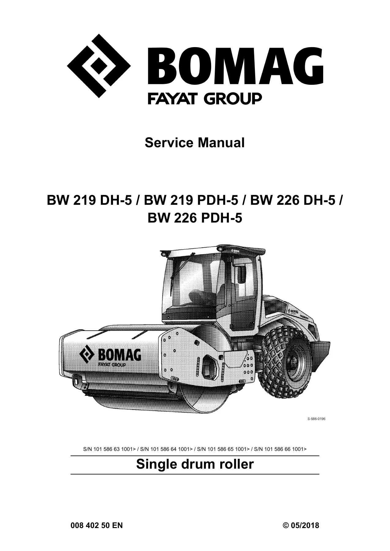
BOMAG BW 219 DH-5 BW 219 PDH-5 BW 226 DH-5 BW 226 PDH-5 Single Drum Roller Service Manual 2018
Original price was: $39.95.$24.95Current price is: $24.95.
Complete 2018 BOMAG service manual for BW 219 DH-5, BW 219 PDH-5, BW 226 DH-5 and BW 226 PDH-5 single drum rollers — engine, hydraulics, electrics, drum, axle, diagnostics, wiring and hydraulic diagrams.
Description
BOMAG BW 219 DH-5 / BW 219 PDH-5 / BW 226 DH-5 / BW 226 PDH-5 Service Manual
This is the full BOMAG Service Manual for the fifth-generation single drum rollers BW 219 DH-5, BW 219 PDH-5, BW 226 DH-5 and BW 226 PDH-5. It is the same document BOMAG Customer Service and trained technicians use in the workshop, and it covers these four rollers end-to-end: diesel engine, travel and vibration hydraulics, electrics and CAN bus, drum assembly, drive axle, air conditioning, auxiliary heating and ROPS/FOPS mounting.
Because DH and PDH variants share the same base machine and only differ at the drum (smooth versus padfoot), one manual covers all four models. Every procedure is written with the values, torques, pressures and tolerances a technician actually needs on the shop floor.
File Details
- Manual type: Service Manual (workshop repair and maintenance)
- Brand: BOMAG (FAYAT Group)
- Covered models: BW 219 DH-5, BW 219 PDH-5, BW 226 DH-5, BW 226 PDH-5
- Machine type: Single drum roller
- Document number: 00840250EN
- Edition / date: 2018
- Language: English
- File format: PDF
- Serial number prefixes: S/N 101 586 63 1001>, 101 586 64 1001>, 101 586 65 1001>, 101 586 66 1001>
Chapters Covered
- 1. General information — introduction, safety fundamentals, fuel and lubricant handling, loading and transport, start-up, driving and working operation, refuelling, emergency procedures, maintenance work, repair notes, tightening torques for metric, UNC, UNF and hydraulic fittings.
- 2. Technical data — full specification blocks for each of the four models, plus additional engine, pump, motor, axle and gear data, terms and basis of calculation, fuels and lubricants, and the complete filling capacity list.
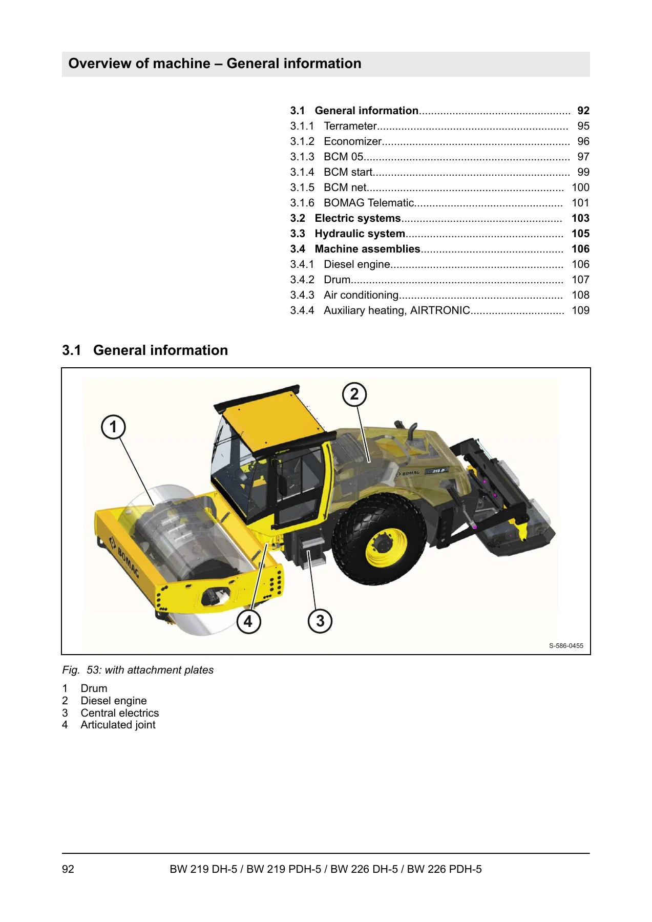
- 3. Overview of machine — machine layout, TERRAMETER, ECONOMIZER, BCM 05, BCM start, BCM net, BOMAG Telematic, electrical layout, hydraulic layout and major machine assemblies.
- 4. Electric systems — measuring methods, circuit diagram reading, Telemecanique switches, Deutsch DT/DTM plugs, central electrics, wiring looms, CAN bus overview, fuse assignment, component descriptions and a full ESX machine control training section with input codes, fault codes and calibration procedures.
- 5. Hydraulic system — open and closed circuits, swash plate pump and motor principles, gear pumps, hydraulic overview, travel/vibration pumps, travel motors, vibration motor, steering valve, charge circuit, travel circuit, vibration circuit, steering circuit, bypass flow filter, flushing and bleeding procedures.
- 6. Machine assemblies — diesel engine overviews, lubrication circuit, cooling circuit, fuel system, Deutz Common Rail, wastegate, EGR, engine electrics and sensors; drum dismantling and assembly, change-over weights, rubber buffers, scrapers, padfoot shells; oscillating articulated joint; drive axle; air conditioning; AIRTRONIC auxiliary heating; cabin assembly; ROPS/FOPS assembly.
- 7. Troubleshooting — emergency procedures and towing, electrical diagnostics, ESX power supply testing, diesel engine malfunction tables, the complete Deutz EMR3 DTC fault code list, hydraulic troubleshooting tables, air conditioning diagnostics and auxiliary heating diagnostics.
- 8. Special tools — special tools for electrics, hydraulic testing and flushing, oscillating articulated joint and drum.
- 9. Index
- Appendix A — Circuit diagrams — full wiring schematic set (drawing 523), hydraulic diagram 479 for BW 219 DH-5 and hydraulic diagram 480 for BW 226 DH-5.
What the BOMAG BW 219 DH-5 / BW 226 DH-5 Service Manual Gives You
The value of this manual is in the details. Where a general workshop guide tells you to remove the drum, this BOMAG service manual tells you which bearing goes in which direction, how hot to heat the inner race, which Loctite to use on the dowel pins, and what the correct end float on the exciter shaft should measure. It covers not just one machine, but four specific fifth-generation single drum rollers and their two drum configurations.
On the Deutz TCD 2012 L06 engine side, the manual documents the Common Rail fuel system, the wastegate charge pressure control, the externally cooled exhaust gas recirculation system and the EMR3 engine electrics with the full pin assignment of the control unit. Sensor replacement procedures are laid out individually: camshaft speed sensor B114, crankshaft speed sensor B130, rail pressure sensor B93, fuel pressure sensor B145, oil pressure sensor B88, charge air temperature and pressure sensor B133 and coolant temperature sensor B113.
For the hydraulic system the manual breaks down the pump and motor units by manufacturer and model: Sauer H1 P089 travel pumps, Sauer H1 B110 travel motors, Sauer H1 P078 vibration pump, Bosch-Rexroth A2FM 63 and A2FM 80 vibration motors, Danfoss OSPC 500 ON steering valve and Dana CHC 193/99 drive axle with no-spin differential. Each unit gets its own service description with charge pressure, high pressure limitation, pressure override and flushing pressure values.
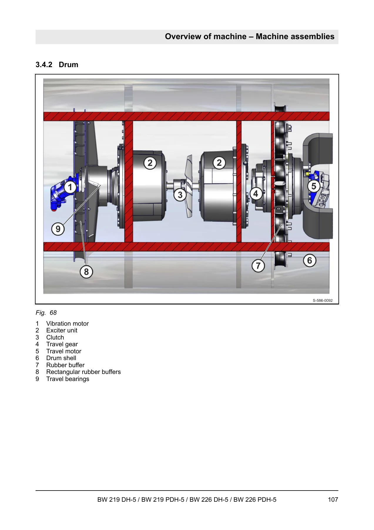
The drum section is fully documented down to component level — exciter unit disassembly from both the travel motor side and the vibration motor side, change-over weight removal and refilling, rubber buffer replacement with pretension adjustment, mechanical seal installation with assembly devices, and full smooth drum and padfoot shell removal and reinstallation procedures with torque values.
Electrical and Diagnostic Coverage
The electric systems chapter is effectively a training course on the machine control. It walks through the measuring method, how to read the circuit diagrams, how to handle the Telemecanique switch blocks and the Deutsch DT and DTM connectors, and then covers the central electrics, wiring harnesses and the full CAN bus architecture (CAN 1, CAN 2, CAN 3 and CAN 4).
Fuse assignments are given for the central electrics, main fuses, cabin control console and auxiliary heating. Component descriptions cover the acceleration transducers B62 and B171, the hydraulic oil filter differential pressure switch B21, air filter vacuum switch B03, water-in-fuel sensor B124, coolant float switch B55, diesel tank level sensor R03, charge control light and the electric module A108.
The ESX machine control training section is the deepest part of the electrical documentation. It gives step-by-step service mode access via the travel lever, the complete input code list, the firmware version decoding, fault log display and deletion, machine type adjustment, automatic surge current detection for the travel system, travel pump coil current and pressure displays, speed detection calibration, vibration frequency setting, cabin activation, serial number entry, cross-slope sensor adjustment and the double pump flushing and individual pump test modes.
Troubleshooting and Fault Codes
The troubleshooting chapter is written for the technician who already has a fault on the machine. It explains the diagnostics concept, the fault description and questioning process, how to determine whether a fault sits in the component or in the wiring, and how to run the electrical power supply check on the ESX control using the pinbox or measuring cables. The complete Deutz EMR3 DTC fault code list follows — from air filter differential pressure code 11 and barometric pressure code 16 all the way through injector bank errors, rail pressure monitoring codes, main relay diagnostics and the DEF and SCR aftertreatment fault codes on Tier 4f machines.
Hydraulic troubleshooting is handled separately with tables for axial piston pumps and axial piston motors, plus a full component-level troubleshooting table covering drive elements, cylinders, motors, flow valves, pressure valves, accumulators, filters, radiators, suction conditions, hydraulic oil tanks and drive motors. Air conditioning and auxiliary heating diagnostics are included with their own pressure charts, resistance tables, magnetic clutch checks and fuel delivery measurement procedures.
Why This Manual Matters for BW 219 DH-5 and BW 226 DH-5 Owners
These rollers are hydrostatically driven and hydrostatically vibrated machines — the travel circuit, vibration circuit, steering circuit and charge circuit all interact. A wrong charge pressure, a contaminated filter or an incorrectly set pressure override valve can take the whole machine out of service. The BOMAG service manual gives you the correct starting point for every adjustment, the correct torque for every critical fastener, and the correct sequence for every assembly procedure.
Because it covers the fourth-generation upgrades as well — the switch to the Common Rail TCD 2012 engine, the integrated air conditioning and AIRTRONIC auxiliary heating, the BCM compaction management options and the BOMAG Telematic system — this is not an outdated document. The serial number prefixes listed confirm it applies to machines from S/N 101 586 63 1001 onwards.
Chapters at a Glance
Whether you need to change the oil in the exciter housing, replace a rubber buffer, reseal the oscillating articulated joint, adjust the parking brake on the Dana axle, service the air conditioning compressor, check the coolant temperature sensor resistance or look up a specific EMR3 fault code, this BOMAG single drum roller service manual is the reference you reach for first. The appendix circuit diagrams (drawing 523) and hydraulic diagrams (479 and 480) provide the schematics needed for actual fault tracing rather than guesswork.
Instant PDF Delivery — No Shipping, No Waiting
The manual is delivered as a PDF the moment your order is completed. There is no physical book to wait for, no shipping cost and no chance of a lost parcel. Open it on a laptop in the workshop, a tablet beside the machine, or a phone in the field, and print any page you need — a single torque table, a wiring sheet or the whole drum assembly section.
For anyone maintaining or repairing a BW 219 DH-5, BW 219 PDH-5, BW 226 DH-5 or BW 226 PDH-5, having the genuine BOMAG service manual on hand turns a difficult job into a documented one. The correct procedure, the right specification and the correct torque value are all in this file.
Reviews
There are no reviews yet.