Description
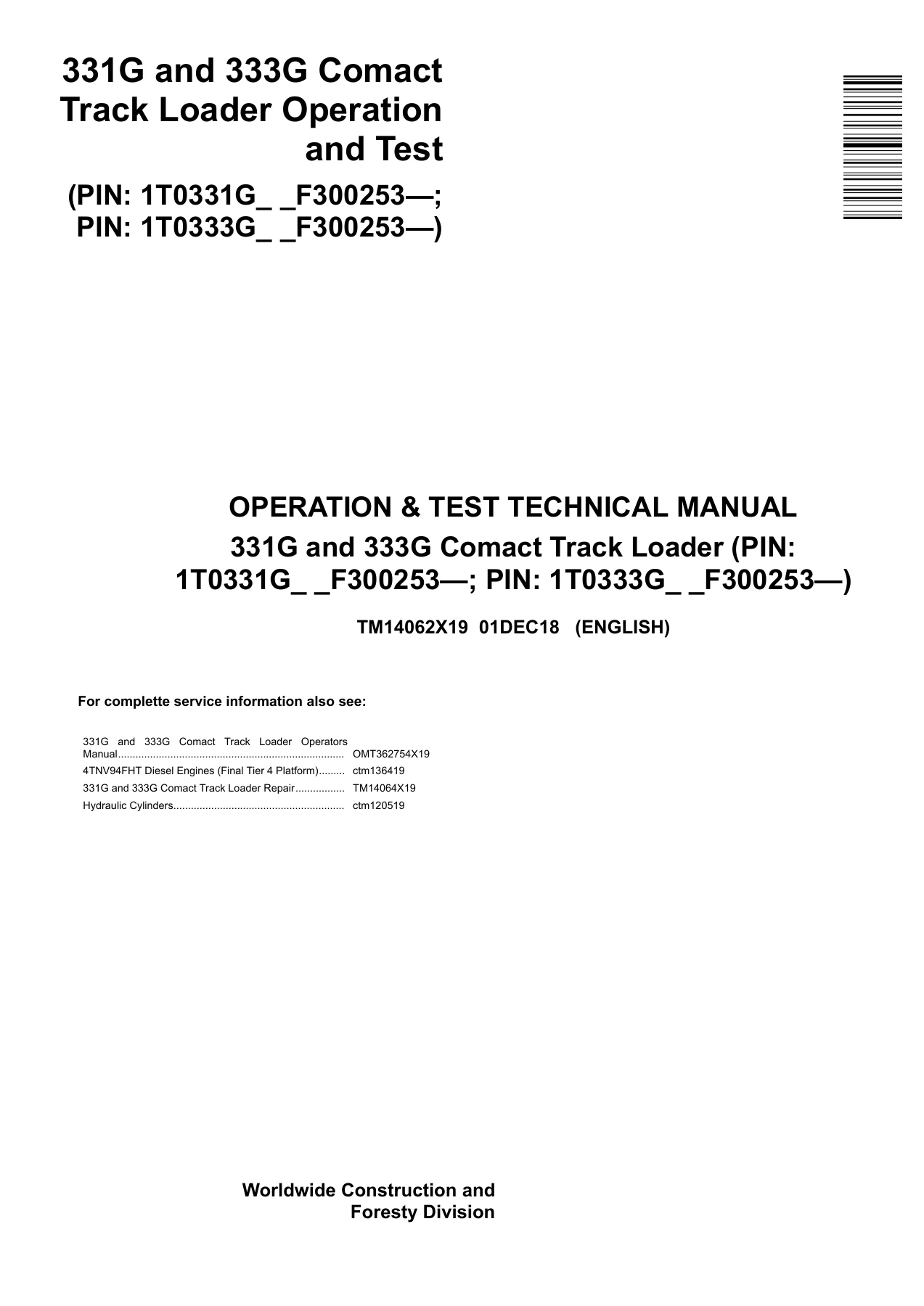
John Deere 331G 333G Compact Track Loader Operation and Test Manual – TM14062X19
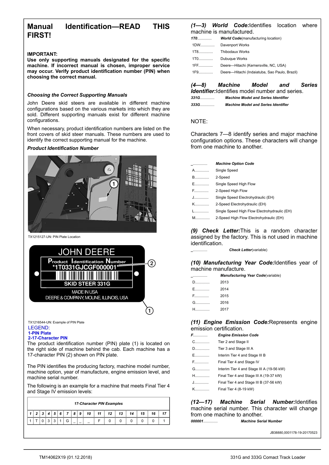
This is the complete John Deere 331G and 333G Compact Track Loader Operation and Test Technical Manual, document number TM14062X19, published 01DEC18 in English. It covers machines from PIN 1T0331G _ _ F300253— and PIN 1T0333G _ _ F300253— onward and belongs to the same technical documentation set John Deere dealership technicians use on the shop floor for diagnostics, operational testing, and troubleshooting on the 331G and 333G compact track loaders.
File Details
- Manual Type: Operation and Test Technical Manual
- Brand: John Deere
- Models Covered: 331G, 333G Compact Track Loader
- Document Number: TM14062X19
- Edition / Date: 01DEC18 (December 2018)
- Language: English
- Page Count: 651 pages
- File Format: PDF
- Serial Number Coverage: PIN 1T0331G _ _ F300253— ; PIN 1T0333G _ _ F300253—
What This Operation and Test Manual Delivers
Unlike a plain repair manual, this John Deere 331G 333G Operation and Test Manual TM14062X19 is built around the diagnostic workflow: how to identify the majority of routine failures quickly, how each subsystem is supposed to behave, and how to confirm what is wrong before a single component comes off the machine. Operation sections give the theory behind each system, test sections give the pressure, flow, voltage, resistance, and drift values a technician uses to compare against, and the extensive Diagnostic Trouble Code (DTC) library gives the fault description, alarm level, machine response, and possible causes for each code.
Because the manual is organized by component group, each group opens with a summary listing of the essential tools, service equipment, materials, service parts kits, specifications, wear tolerances, and torque values required for that job. That structure lets a technician move from a symptom to the right test procedure without hunting through unrelated sections.
Chapters and Systems Covered
The contents below reflect the manual’s actual organization, running from general information and safety through to the dealer-fabricated tools appendix.
Complete PDF Bookmark Tree
Complete Bookmarks
The complete bookmarks in the “John Deere 331G 333G Compact Track Loader Operation and Test Manual TM14062X19 PDF” are as follows:
+Introductionp. 2
Forewordp. 2
Manual Identification—READ THIS FIRST!p. 3
Contentsp. 4
+General Informationp. 5
+Safetyp. 6
Recognize Safety Informationp. 6
Follow Safety Instructionsp. 6
Operate Only If Qualifiedp. 6
Wear Protective Equipmentp. 7
Avoid Unauthorized Machine Modificationsp. 7
Inspect Machinep. 7
Stay Clear of Moving Partsp. 7
Avoid High-Pressure Fluidsp. 8
Avoid High-Pressure Oilsp. 8
Work In Ventilated Areap. 8
Avoid Static Electricity Risk When Refuelingp. 9
Prevent Firesp. 9
In Case of Machine Firep. 10
Prevent Battery Explosionsp. 10
Handle Chemical Products Safelyp. 10
Handle Starting Fluid Safelyp. 11
Decommissioning—Proper Recycling and Disposal of Fluids and Componentsp. 11
Exhaust Filter Ash Handling and Disposalp. 11
Prepare for Emergenciesp. 12
Clean Debris from Machinep. 12
Add Cab Guarding for Special Usesp. 12
Use Steps and Handholds Correctlyp. 12
Start Only From Operator′s Seatp. 13
Use and Maintain Seat Beltp. 13
Prevent Unintended Machine Movementp. 13
Avoid Work Site Hazardsp. 14
Keep Riders Off Machinep. 14
Avoid Backover Accidentsp. 14
Avoid Machine Tip Overp. 15
Operating On Slopesp. 15
Operating or Traveling On Public Roadsp. 15
Inspect and Maintain ROPSp. 15
Travel Safelyp. 16
Prevent Acid Burnsp. 16
Add and Operate Attachments Safelyp. 16
Park and Prepare for Service Safelyp. 17
Service Cooling System Safelyp. 17
Remove Paint Before Welding or Heatingp. 17
Make Welding Repairs Safelyp. 18
Drive Metal Pins Safelyp. 18
Service Tires Safelyp. 18
Handle Cab Door Safely—If Equippedp. 19
Clean Exhaust Filter Safelyp. 19
+Diagnosticsp. 21
+Dosing Control Unit (DCU) Diagnostic Trouble Codesp. 25
Dosing Control Unit (DCU) Diagnostic Trouble Codesp. 25
001761.01— DEF Level Very Lowp. 25
001761.03— DEF Level Circuit Faultp. 25
001761.04— DEF Level Circuit Faultp. 25
001761.13— DEF Level Calibrationp. 26
001761.15— DEF Level Slightly Highp. 26
001761.18— DEF Level Moderately Lowp. 27
003031.00— DEF Temperature Very Highp. 27
003031.02— DEF Temperature Invalidp. 27
003031.03— DEF Temperature Circuit Faultp. 28
003031.04— DEF Temperature Circuit Faultp. 28
003031.13— DEF Temperature Calibrationp. 28
003031.15— DEF Temperature Slightly Highp. 28
003031.17— DEF Temperature Slightly Lowp. 29
003515.02— DEF Sensor Value Invalidp. 29
003515.03— DEF Sensor Circuit Faultp. 30
003515.04— DEF Sensor Circuit Faultp. 30
003515.13— DEF Sensor Calibrationp. 30
003516.00— DEF Concentration Very Highp. 31
003516.01— DEF Concentration Very Lowp. 31
003516.03— DEF Concentration Circuit Faultp. 31
003516.04— DEF Concentration Circuit Faultp. 32
003516.13— DEF Concentration Calibrationp. 32
003521.13— DEF Fluid Calibrationp. 32
004334.03— DEF Dosing Unit Pump Circuit Faultp. 34
004334.04— DEF Dosing Unit Pump Circuit Faultp. 35
004334.15— DEF Dosing Unit Pump Slightly Highp. 35
004334.17— DEF Dosing Unit Pump Slightly Lowp. 36
004366.05— DEF Tank Heater Coolant Control Valve Circuit Has High Resistancep. 37
004366.06— DEF Tank Heater Coolant Control Valve Circuit Has Low Resistancep. 41
004366.16— DEF Tank Temperature Moderately Highp. 44
004366.18— DEF Tank Insufficient Heating Faultp. 47
005137.00— DEF Heating Valve Very Highp. 51
005137.04— DEF Heating Valve Circuit Faultp. 52
005137.05— DEF Heating Valve Circuit Faultp. 53
523555.03— DEF Heating Valve Circuit Faultp. 54
523555.04— DEF Heating Valve Circuit Faultp. 55
523560.02— Main Relay Invalidp. 56
523560.07— Main Relay Faultp. 57
523581.00— Temperature Sensor Very Highp. 57
523592.00— Heater Relay Very Highp. 59
523592.03— Heater Relay Circuit Faultp. 60
523592.04— Heater Relay Circuit Faultp. 61
523592.05— Heater Relay Circuit Faultp. 62
523594.03— DEF Tank Heater Circuit Faultp. 63
523630.02— DEF Temperature Sensor Invalidp. 64
523634.09— DEF Sensor Communication Faultp. 64
523635.09— DEF Sensor Communication Faultp. 65
523640.05— DCU Supply Voltage Circuit Faultp. 65
+Engine Control Unit (ECU) Diagnostic Trouble Codesp. 66
Engine Control Unit (ECU) Diagnostic Trouble Codesp. 66
000028.00— Service Throttle Very Highp. 67
000028.01— Service Throttle Very Lowp. 68
000028.03— Service Throttle Circuit Faultp. 69
000028.04— Service Throttle Circuit Faultp. 70
000029.00— Foot Throttle Very Highp. 71
000029.01— Foot Throttle Very Lowp. 73
000029.02— Foot Throttle Invalidp. 75
000029.03— Foot Throttle Circuit Faultp. 76
000029.04— Foot Throttle Circuit Faultp. 78
000029.08— Foot Throttle Signal Faultp. 80
000029.15— Foot Throttle Slightly Highp. 81
000091.00— Hand Throttle Very Highp. 83
000091.01— Hand Throttle Very Lowp. 84
000091.02— Hand Throttle Invalidp. 86
000091.03— Hand Throttle Circuit Faultp. 87
000091.04— Hand Throttle Circuit Faultp. 88
000091.08— Hand Throttle Signal Faultp. 90
000091.15— Hand Throttle Slightly Highp. 91
000100.01— Oil Pressure Very Lowp. 92
000100.04— Oil Pressure Circuit Faultp. 93
000158.00— System Voltage Very Highp. 94
000158.01— System Voltage Very Lowp. 95
000167.01— System Voltage Very Lowp. 96
000167.04— System Voltage Circuit Faultp. 97
000167.05— System Voltage Circuit Faultp. 98
000237.13— Vehicle ID Calibrationp. 99
000237.31— Vehicle ID Faultp. 99
001202.02— ECU Invalidp. 99
001485.02— Main Relay Invalidp. 101
001485.07— Main Relay Circuit Faultp. 102
522243.02— Start Aid Invalidp. 103
522243.03— Start Aid Circuit Faultp. 104
522243.04— Start Aid Circuit Faultp. 105
522243.05— Start Aid Circuit Faultp. 106
522243.06— Start Aid Circuit Faultp. 107
522314.00— Coolant Temperature Very Highp. 108
522323.00— Eng Air Filter Restr Very Highp. 108
522596.09— ECU Communication Faultp. 108
522597.09— ECU Communication Faultp. 109
522599.09— ECU Communication Faultp. 109
522600.09— ECU Communication Faultp. 109
522601.09— ECU Communication Faultp. 110
522609.09— EGR Communication Faultp. 110
522618.09— ECU Communication Faultp. 110
522619.09— ECU Communication Faultp. 111
522730.08— ECU Signal Faultp. 111
522730.12— ECU Faultp. 111
522994.04— ECU Circuit Faultp. 112
523513.09— DCU Communication Faultp. 112
+Engagement and Monitor Unit (EMU) Diagnostic Trouble Codesp. 113
Engagement and Monitor Unit (EMU) Diagnostic Trouble Codesp. 113
000096.03— Fuel Level Circuit Faultp. 114
000096.04— Fuel Level Circuit Faultp. 116
000158.00— System Voltage Very Highp. 118
000158.01— System Voltage Very Lowp. 119
000162.04— 2-Speed Switch Circuit Faultp. 120
000628.12— Programming Faultp. 120
000920.05— Alarm Output Circuit Faultp. 122
000920.06— Alarm Output Circuit Faultp. 123
001196.11— Antitheft Faultp. 123
001504.04— Seat Switch Circuit Faultp. 125
002000.09— ECU Communication Faultp. 126
002142.09— SSM Communication Faultp. 126
002228.09— HCU Communication Faultp. 126
002251.09— SAR Communication Faultp. 127
003413.04— Door Switch Circuit Faultp. 128
521050.04— Aux Flow Switch Circuit Faultp. 129
521197.04— Courtesy Light Sw Circuit Faultp. 131
522379.05— Park Brake Sol Circuit Faultp. 132
522379.06— Park Brake Sol Circuit Faultp. 133
522826.00— Fan Purge Switch Very Highp. 134
522826.04— Fan Purge Switch Circuit Faultp. 136
522827.04— Fan Auto Switch Circuit Faultp. 138
522828.03— Creep Mode Switch Circuit Faultp. 140
522828.04— Creep Mode Switch Circuit Faultp. 142
522828.07— Creep Mode Switch Faultp. 144
522859.04— Lap Bar Switch Circuit Faultp. 146
523217.06— Hyd Valve Power 3 Circuit Faultp. 147
523218.06— Hst Valve Power Circuit Faultp. 148
523219.06— Hyd Valve Power 1 Circuit Faultp. 149
523693.03— Aux Hydraulic In 1 Circuit Faultp. 150
523693.04— Aux Hydraulic In 1 Circuit Faultp. 151
523694.03— Aux Hydraulic In 2 Circuit Faultp. 152
523694.04— Aux Hydraulic In 2 Circuit Faultp. 153
523694.12— Aux Hydraulic In 2 Faultp. 154
523822.04— High Flow Switch Circuit Faultp. 155
523935.05— Aux Hyd Extend Sol Circuit Faultp. 157
523935.06— Aux Hyd Extend Sol Circuit Faultp. 158
523941.05— Aux Hyd Retract Sol Circuit Faultp. 159
523941.06— Aux Hyd Retract Sol Circuit Faultp. 160
523948.05— Ride Control Sol 1 Circuit Faultp. 161
523948.06— Ride Control Sol 1 Circuit Faultp. 162
523949.05— Ride Control Sol 2 Circuit Faultp. 163
523949.06— Ride Control Sol 2 Circuit Faultp. 164
524225.04— Remote Start In Circuit Faultp. 165
524264.11— Checksum Faultp. 166
+Hydraulic Control Unit (HCU) Diagnostic Trouble Codesp. 167
Hydraulic Control Unit (HCU) Diagnostic Trouble Codesp. 167
000630.13— Calibration Memory Calibrationp. 167
001594.00— Left Speed In Very Highp. 168
001594.01— Left Speed In Very Lowp. 170
001594.02— Left Speed In Invalidp. 172
001594.14— Left Speed In Faultp. 174
001595.00— Right Speed In Very Highp. 175
001595.01— Right Speed In Very Lowp. 177
001595.02— Right Speed In Invalidp. 179
001595.14— Right Speed In Faultp. 181
002201.09— Right Joystick Communication Faultp. 182
002213.09— Left Joystick Communication Faultp. 182
002660.07— Right Joystick X Faultp. 182
002661.07— Right Joystick Y Faultp. 183
002697.07— Left Joystick X Faultp. 183
002698.07— Left Joystick Y Faultp. 183
516193.03— Left Pedal In 1 Circuit Faultp. 185
516193.04— Left Pedal In 1 Circuit Faultp. 186
516193.07— Left Pedal In 1 Faultp. 187
516193.16— Left Pedal In 1 Moderately Highp. 188
516193.18— Left Pedal In 1 Moderately Lowp. 189
516194.03— Left Pedal In 2 Circuit Faultp. 190
516194.04— Left Pedal In 2 Circuit Faultp. 191
516195.03— Right Pedal In 2 Circuit Faultp. 192
516195.04— Right Pedal In 2 Circuit Faultp. 193
516196.03— Right Pedal In 1 Circuit Faultp. 194
516196.04— Right Pedal In 1 Circuit Faultp. 195
516196.07— Right Pedal In 1 Faultp. 196
516196.16— Right Pedal In 1 Moderately Highp. 197
516196.18— Right Pedal In 1 Moderately Lowp. 198
516197.06— Hyd Port Lock Sol Circuit Faultp. 199
520652.05— Bucket Curl Sol Circuit Faultp. 200
520652.06— Bucket Curl Sol Circuit Faultp. 201
520653.05— Bucket Dump Sol Circuit Faultp. 202
520653.06— Bucket Dump Sol Circuit Faultp. 203
520882.13— Loader Threshold Calibrationp. 203
522377.03— Boom Position In 1 Circuit Faultp. 204
522377.04— Boom Position In 1 Circuit Faultp. 205
522377.12— Boom Position In 1 Faultp. 206
522377.13— Boom Position In 1 Calibrationp. 207
522378.03— Boom Position In 2 Circuit Faultp. 208
522378.04— Boom Position In 2 Circuit Faultp. 209
522436.03— Bucket Position In 1 Circuit Faultp. 210
522436.04— Bucket Position In 1 Circuit Faultp. 211
522436.12— Bucket Position In 1 Faultp. 212
522436.13— Bucket Position In 1 Calibrationp. 213
522437.03— Bucket Position In 2 Circuit Faultp. 214
522437.04— Bucket Position In 2 Circuit Faultp. 215
522447.05— Right Pump Fwd Sol Circuit Faultp. 216
522447.06— Right Pump Fwd Sol Circuit Faultp. 217
522448.05— Right Pump Rev Sol Circuit Faultp. 218
522448.06— Right Pump Rev Sol Circuit Faultp. 219
522449.05— Left Pump Rev Sol Circuit Faultp. 220
522449.06— Left Pump Rev Sol Circuit Faultp. 221
522450.05— Left Pump Fwd Sol Circuit Faultp. 222
522450.06— Left Pump Fwd Sol Circuit Faultp. 223
522507.13— Loader Angle Calibrationp. 223
523108.13— Transmission Calibrationp. 224
523217.03— Hyd Valve Power 3 Circuit Faultp. 225
523217.04— Hyd Valve Power 3 Circuit Faultp. 226
523218.03— Hst Valve Power Circuit Faultp. 227
523218.04— Hst Valve Power Circuit Faultp. 228
523219.03— Hyd Valve Power 1 Circuit Faultp. 229
523219.04— Hyd Valve Power 1 Circuit Faultp. 230
523411.05— Boom Down Sol Circuit Faultp. 231
523411.06— Boom Down Sol Circuit Faultp. 232
523411.16— Boom Down Sol Moderately Highp. 233
523414.05— Boom Up Sol Circuit Faultp. 234
523414.06— Boom Up Sol Circuit Faultp. 235
523414.16— Boom Up Sol Moderately Highp. 236
+Left Joystick Controller (JSL) Diagnostic Trouble Codesp. 237
Left Joystick Controller (JSL) Diagnostic Trouble Codesp. 237
002697.03— Left Joystick X Circuit Faultp. 237
002697.04— Left Joystick X Circuit Faultp. 237
002697.13— Left Joystick X Calibrationp. 238
002697.14— Left Joystick X Faultp. 238
002698.03— Left Joystick Y Circuit Faultp. 238
002698.04— Left Joystick Y Circuit Faultp. 239
002698.13— Left Joystick Y Calibrationp. 239
002698.14— Left Joystick Y Faultp. 239
+Right Joystick Controller (JSR) Diagnostic Trouble Codesp. 241
Right Joystick Controller (JSR) Diagnostic Trouble Codesp. 241
002660.03— Right Joystick X Circuit Faultp. 241
002660.04— Right Joystick X Circuit Faultp. 241
002660.13— Right Joystick X Calibrationp. 242
002660.14— Right Joystick X Faultp. 242
002661.03— Right Joystick Y Circuit Faultp. 242
002661.04— Right Joystick Y Circuit Faultp. 243
002661.13— Right Joystick Y Calibrationp. 243
002661.14— Right Joystick Y Faultp. 243
+Sealed Switch Module (SSM) Diagnostic Trouble Codesp. 245
Sealed Switch Module (SSM) Diagnostic Trouble Codesp. 245
000629.12— Control Unit Faultp. 245
002033.09— VCU Communication Faultp. 245
002634.04— Ignition Relay Circuit Faultp. 246
002634.05— Ignition Relay Circuit Faultp. 247
003997.04— Wake Up Output Circuit Faultp. 248
003997.05— Wake Up Output Circuit Faultp. 249
523850.04— SSM Button 15 Circuit Faultp. 250
523850.09— SSM Button 15 Communication Faultp. 250
523852.04— SSM Button 14 Circuit Faultp. 250
523852.09— SSM Button 14 Communication Faultp. 251
523854.04— SSM Button 13 Circuit Faultp. 251
523854.09— SSM Button 13 Communication Faultp. 252
523855.04— SSM Button 12 Circuit Faultp. 252
523855.09— SSM Button 12 Communication Faultp. 252
523856.04— SSM Button 11 Circuit Faultp. 253
523856.09— SSM Button 11 Communication Faultp. 253
523857.04— SSM Button 10 Circuit Faultp. 254
523857.09— SSM Button 10 Communication Faultp. 254
523858.04— SSM Button 9 Circuit Faultp. 254
523858.09— SSM Button 9 Communication Faultp. 255
523860.04— SSM Button 8 Circuit Faultp. 255
523860.09— SSM Button 8 Communication Faultp. 256
523861.04— SSM Button 7 Circuit Faultp. 256
523861.09— SSM Button 7 Communication Faultp. 256
523862.04— SSM Button 6 Circuit Faultp. 257
523862.09— SSM Button 6 Communication Faultp. 257
523863.04— SSM Button 5 Circuit Faultp. 258
523863.09— SSM Button 5 Communication Faultp. 258
523864.04— SSM Button 4 Circuit Faultp. 258
523864.09— SSM Button 4 Communication Faultp. 259
523865.04— SSM Button 3 Circuit Faultp. 259
523865.09— SSM Button 3 Communication Faultp. 259
523867.04— SSM Button 2 Circuit Faultp. 260
523867.09— SSM Button 2 Communication Faultp. 260
523868.04— SSM Button 1 Circuit Faultp. 261
523868.09— SSM Button 1 Communication Faultp. 261
+Vehicle Control Unit (VCU) Diagnostic Trouble Codesp. 262
Vehicle Control Unit (VCU) Diagnostic Trouble Codesp. 262
000100.03— Oil Pressure Circuit Faultp. 263
000158.03— System Voltage Circuit Faultp. 264
000158.04— System Voltage Circuit Faultp. 265
000168.03— Battery Voltage Circuit Faultp. 266
000168.04— Battery Voltage Circuit Faultp. 267
000628.12— Programming Faultp. 268
000977.05— Fan Direction Sol Circuit Faultp. 269
000977.06— Fan Direction Sol Circuit Faultp. 270
001071.05— Fan Speed Sol Circuit Faultp. 271
001071.06— Fan Speed Sol Circuit Faultp. 272
001508.00— Hydraulic Oil Temp Very Highp. 273
001508.03— Hydraulic Oil Temp Circuit Faultp. 274
001508.04— Hydraulic Oil Temp Circuit Faultp. 275
001713.00— Hyd Filter Switch Very Highp. 276
001713.03— Hyd Filter Switch Circuit Faultp. 277
003512.03— Sensor Supply 4 Circuit Faultp. 278
003512.04— Sensor Supply 4 Circuit Faultp. 279
003597.03— Sensor Supply 1 Circuit Faultp. 280
003597.04— Sensor Supply 1 Circuit Faultp. 281
003598.03— Sensor Supply 2 Circuit Faultp. 282
003598.04— Sensor Supply 2 Circuit Faultp. 283
004056.05— 2-Speed Output Circuit Faultp. 284
004056.06— 2-Speed Output Circuit Faultp. 285
516249.04— Sensor Supply 1 Circuit Faultp. 285
520194.13— Vehicle ID Calibrationp. 286
520194.14— Vehicle ID Faultp. 286
520714.05— Self Level Circuit Faultp. 288
520714.06— Self Level Circuit Faultp. 289
520849.03— Right JS Trigger Circuit Faultp. 290
520849.04— Right JS Trigger Circuit Faultp. 292
521466.05— Fan Direction Sol Circuit Faultp. 294
521466.06— Fan Direction Sol Circuit Faultp. 295
521806.05— Hst Bypass Sol Circuit Faultp. 296
521806.06— Hst Bypass Sol Circuit Faultp. 297
522329.00— Water In Fuel Very Highp. 298
522820.05— High Flow Sol Circuit Faultp. 299
522820.06— High Flow Sol Circuit Faultp. 300
524084.00— Hst Oil Temp Very Highp. 301
524084.03— Hst Oil Temp Circuit Faultp. 302
524084.04— Hst Oil Temp Circuit Faultp. 303
524264.11— Checksum Errorp. 303
+Rear Camera Display (VC1) Diagnostic Trouble Codesp. 305
000629.12— Control Unit Faultp. 305
516628.10— Monitor Button Faultp. 305
516629.10— Monitor Button Faultp. 305
516630.10— Monitor Button Faultp. 306
520760.02— Camera Signal Invalidp. 306
521857.10— Monitor Button Faultp. 306
521858.10— Monitor Button Faultp. 307
521859.10— Monitor Button Faultp. 307
+Operational Checkout Procedurep. 308
+Operational Checkout Procedurep. 309
Operational Checkoutp. 309
+Enginep. 321
+Theory of Operationp. 322
John Deere Enginep. 322
Exhaust Aftertreatmentp. 322
Cold Start Operationp. 322
+System Diagramsp. 324
John Deere Enginep. 324
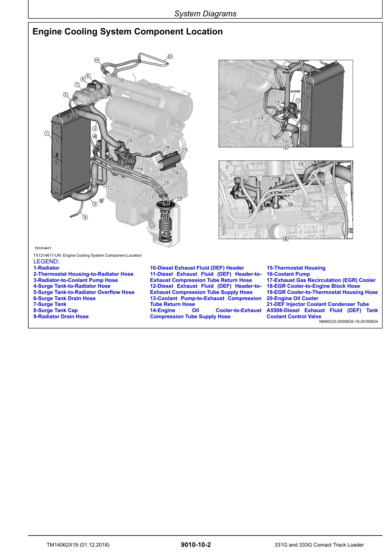
Engine Cooling System Component Locationp. 325
Engine Fuel System Component Locationp. 326
Engine Intake and Exhaust Component Locationp. 327
+Diagnostic Informationp. 328
John Deere Enginep. 328
Engine Hard to Start or Does Not Start When Coldp. 329
+Adjustmentsp. 331
John Deere Enginep. 331
Service Filter Cleaningp. 331
+Testsp. 332
John Deere Enginep. 332
+Fluid Sampling Procedure—If Equippedp. 333
MACHINE PREPARATIONp. 333
Priming Sample Valvep. 333
Obtaining Fluid Samplep. 333
+Electrical Systemp. 336
+Theory of Operationp. 338
+Starting Circuit Theory of Operationp. 339
Controller Area Network (CAN) Theory of Operationp. 342
Rear Camera Circuit Theory of Operationp. 345
Engine Control Unit (ECU) Circuit Theory of Operationp. 347
+Exhaust Aftertreatment Circuit Theory of Operationp. 356
Diesel Exhaust Fluid (DEF) Systemp. 356
Engagement and Monitor Unit (EMU)—EXHAUST FILTERp. 358
Cleaning Statesp. 359
Passive Cleaningp. 359
Enhanced Passive Cleaningp. 359
Active Cleaningp. 360
Parked Cleaningp. 360
DPF Recoveryp. 361
Ash Removalp. 361
+Engagement and Monitor Unit (EMU) Circuit Theory of Operationp. 362
Interlock Logicp. 364
Auxiliary Hydraulic Operationp. 365
Lighting Circuit Theory of Operationp. 366
Hydraulic System Control Circuit Theory of Operationp. 368
Backup Alarm Circuit Theory of Operationp. 373
Quik-Tatch™ Circuit Theory of Operation—If Equippedp. 375
JDLink™ Circuit Theory of Operationp. 377
Hydrostatic System Control Circuit Theory of Operationp. 379
Hydraulic Fan Control Circuit Theory of Operationp. 384
+System Diagramsp. 387
+Electrical Diagram Informationp. 388
System Functional Schematic Diagramp. 389
Wiring Diagramp. 389
Component Location Diagramp. 390
Electrical Schematic Symbolsp. 391
Fuse and Relay Specificationsp. 392
System Functional Schematic, Component Location, and Wiring Diagram Master Legendp. 394
System Functional Schematicp. 399
Rear Engine Harness (W1) Component Locationp. 401
Rear Engine Harness (W1) Wiring Diagramp. 402
Cab Harness (W2) Component Locationp. 403
Cab Harness (W2) Wiring Diagramp. 404
Left Main Harness (W3) Component Locationp. 406
Left Main Harness (W3) Wiring Diagramp. 407
Right Main Harness (W4) Component Locationp. 409
Right Main Harness (W4) Wiring Diagramp. 410
Dual Flasher Harness (W5) Component Locationp. 412
Dual Flasher Harness (W5) Wiring Diagramp. 413
JDLink™ Harness (W7) Component Locationp. 414
JDLink™ Harness (W7) Wiring Diagramp. 415
Radio Harness (W8) Component Locationp. 416
Radio Harness (W8) Wiring Diagramp. 417
Rear Camera Harness (W10) Component Locationp. 417
Rear Camera Harness (W10) Wiring Diagramp. 418
Attachment Control Frame Harness (W11) Component Locationp. 418
Attachment Control Frame Harness (W11) Wiring Diagramp. 419
Attachment Control Boom Harness (W12) Component Locationp. 420
Attachment Control Boom Harness (W12) Wiring Diagramp. 421
Heater and Air Conditioner Harness (W17) Component Locationp. 422
Heater and Air Conditioner Harness (W17) Wiring Diagramp. 423
Creep Mode Speed Switch Harness (W19) Component Locationp. 424
Creep Mode Speed Switch Harness (W19) Wiring Diagramp. 425
Engine Interface Harness (W20) Component Locationp. 426
Engine Interface Harness (W20) Wiring Diagramp. 427
Engine Harness (W21) Component Locationp. 428
Engine Harness (W21) Wiring Diagramp. 429
Engine Fuel System Harness (W22) Component Locationp. 429
Engine Fuel System Harness (W22) Wiring Diagramp. 430
Pedal Interface Harness (W23) Component Locationp. 430
+Pedal Interface Harness (W23) Wiring Diagramp. 431
Left Pedalp. 431
Right Pedalp. 432
Joystick Jumper Harness (W25) Component Locationp. 433
+Joystick Jumper Harness (W25) Wiring Diagramp. 434
Right Joystickp. 434
Left Joystickp. 434
Diesel Exhaust Fluid (DEF) Control Valve Harness (W29) Component Locationp. 435
Diesel Exhaust Fluid (DEF) Control Valve Harness (W29) Wiring Diagramp. 435
Quik-Tatch™ Frame Harness (W40) Component Locationp. 435
Quik-Tatch™ Frame Harness (W40) Wiring Diagramp. 436
Quik-Tatch™ Boom Harness (W42) Component Locationp. 437
Quik-Tatch™ Boom Harness (W42) Wiring Diagramp. 438
Quik-Tatch™ Actuator Harness (W44) Component Locationp. 438
Quik-Tatch™ Actuator Harness (W44) Wiring Diagramp. 439
+Diagnostic Informationp. 440
Service ADVISOR™ Connection Procedurep. 440
JDLink™ Connection Procedurep. 441
+Reading Diagnostic Trouble Codes (DTCs)p. 442
Reading Diagnostic Trouble Codes (DTCs) with Engagement Monitor Unit (EMU)p. 442
Reading Diagnostic Trouble Codes (DTCs) with Service ADVISOR™p. 442
Intermittent Diagnostic Trouble Code (DTC) Diagnosticsp. 443
+Monitor Operationp. 444
+Service Modep. 444
To enter service mode:p. 444
Exhaust Filter Service Cleaningp. 445
Exhaust Filter Set Auto Cleanp. 445
Shift Modep. 445
Codesp. 445
Diagnostics—Switchesp. 446
Diagnostics—Sensorsp. 447
Diagnostics—Left Joystickp. 447
Diagnostics—Right Joystickp. 447
Diagnostics—Speedsp. 447
Diagnostics—VCU Outputsp. 449
Diagnostics—EMU Outputsp. 450
Diagnostics—ECU Outputsp. 450
Diagnostics—VCU Powerp. 450
Diagnostics—EMU Powerp. 450
Diagnostics—ECU Powerp. 451
+Diagnostics—Controller Infop. 451
Diagnostics—Controller Infop. 451
Diagnostics—Cal Valuesp. 452
Antitheft—Master Codep. 452
Calibrationp. 453
Owner Controlsp. 453
+Anti-Theft Security System Configuration—If Equippedp. 455
Selecting the Locking Methodp. 455
Changing an Operator or Owner Security Codep. 455
Resetting Operator and Owner Security Codesp. 456
Changing System Security Code Lengthp. 456
+Anti-Theft Security System Enable—If Equippedp. 458
Enable the Anti-Theft Security Systemp. 458
+Anti-Theft Security System Operation—If Equippedp. 459
Locking Machine (operator and owner)p. 459
Unlocking Machine (operator and owner)p. 459
Engagement and Monitor Unit Display Messagesp. 460
Engagement and Monitor Unit Operationp. 462
+Diagnostic Test Boxp. 464
+Setup and Functional Testp. 464
Diagnostic Test Box—Overview and Functionalityp. 464
Before Connecting JDG10273 Diagnostic Test Boxp. 464
JDG10273 Diagnostic Test Box—User Instructionsp. 465
JDG10273 Diagnostic Test Box—Operational Test Procedurep. 465
Test Leadsp. 466
Two Wire Sensor Circuit Check—Out of Range Highp. 467
Two Wire Sensor Circuit Check—Out of Range Lowp. 469
Three Wire Sensor Circuit Check—Out of Range Highp. 470
Three Wire Sensor Circuit Check—Out of Range Lowp. 472
+Adjustmentsp. 474
Hydrostatic System Calibrationp. 474
Boom and Bucket Calibrationp. 476
Auxiliary Hydraulics Calibrationp. 477
Manual Tracking Adjustmentp. 477
Electrohydraulic (EH) Foot Pedal Calibrationp. 478
+Testsp. 479
Electrical Component Checksp. 479
Electrical Component Specificationsp. 483
Solenoid Testp. 485
Alternator Testp. 493
Controller Area Network (CAN) Circuit Testp. 494
+Power Trainp. 500
+Theory of Operationp. 501
Power Train System Operationp. 502
+System Diagramsp. 504
Power Train Component Locationp. 504
+Diagnostic Informationp. 505
Loose Trackp. 505
Tight Trackp. 506
Frequent Track Tension Adjustment Requiredp. 506
Excessive Oil Leakage From Idlers And Rollersp. 506
‘Popping”Of Trackp. 507
Individual Undercarriage Component Wearp. 507
+Adjustmentsp. 508
Check and Adjust Track Tensionp. 508
+Hydraulic Systemp. 511
+Theory of Operationp. 512
Hydraulic System Operationp. 512
Hydraulic Oil Filter Manifold Operationp. 513
High Flow Pump Operation—If Equippedp. 514
Self Leveling Valve Operation—If Equippedp. 516
Ride Control Operation—If Equippedp. 517
Hydraulic Pump Operationp. 518
Hydraulic Fan Operationp. 519
Hydraulic Control Valve Operationp. 522
+System Diagramsp. 525
Hydraulic System Schematicp. 525
Hydraulic System Component Locationp. 526
+Diagnostic Informationp. 527
Diagnose Hydraulic System Malfunctionsp. 527
No Hydraulic Functionsp. 528
Boom Will Not Raisep. 530
Boom Will Not Lowerp. 532
Bucket Will Not Dumpp. 534
Bucket Will Not Curlp. 536
Bucket Will Not Self Level When Boom is Raisedp. 538
Bucket Dumps During Self Leveling Cyclep. 539
Boom Drifts Downp. 540
Boom Drifts Upp. 541
Bucket Drifts Downp. 542
Bucket Drifts Upp. 544
Hydraulic Functions Slow or No Powerp. 546
Hydraulic Functions‘Jerky”or‘Spongy”p. 548
Hydraulic System Noisep. 550
Hydraulic Oil Overheatsp. 552
Hydraulic Fan System Malfunctionsp. 554
Hydraulic Fan Will Not Reverse Directionp. 556
+Adjustmentsp. 557
Ride Control Accumulator Gas Charge Procedure—If Equippedp. 557
+Testsp. 559
JT05800 Digital Thermometer Installationp. 559
JT02156A Digital Pressure and Temperature Analyzer Kit Installationp. 559
Remote Start Box Installationp. 560
Hydraulic System Pressure Releasep. 560
Port Lock Solenoid Valve and Port Lock Spool Testp. 561
Hydraulic System Relief Valve Testp. 562
Charge Pressure Relief Valve Testp. 564
High Flow Relief Valve Testp. 566
+Circuit Relief Valve Testp. 567
Boom Up Circuit Relief Testp. 567
Bucket Dump Circuit Relief Testp. 568
Bucket Curl Circuit Relief Testp. 569
+Function Drift Testp. 571
Boom Down Drift Checkp. 571
Boom Up Drift Checkp. 571
Bucket Dump Drift Checkp. 572
Bucket Curl Drift Checkp. 573
Hydraulic Cylinder Leakage Testp. 574
+Hydraulic Pump Flow Testp. 575
Hydraulic Pump Flow Test—Direct Pump Connectionp. 575
Hydraulic Pump Flow Test—Auxiliary Coupler Connectionp. 576
Charge Pump Flow Testp. 578
+Hydraulic Fan Motor Speed Testp. 580
Hydraulic Fan Speed Test—Machine Coldp. 580
Hydraulic Fan Speed Test—Maximum Speedp. 581
Hydraulic Fan Motor Case Drain Testp. 583
Auxiliary Coupler Manifold Leakage Testp. 585
+Hydrostatic Systemp. 586
+Theory of Operationp. 587
Hydrostatic System Operationp. 587
Hydrostatic Pump Operationp. 588
Charge Pump Operationp. 590
+Hydrostatic Motor Operation—Two-Speedp. 592
Closed-Loop Shuttle Spool and Relief Valve Operationp. 594
Two-Speedp. 595
Electrohydraulic (EH) Operationp. 595
+Hydrostatic Control Valve Operationp. 596
Park Brake System Operationp. 598
+System Diagramsp. 600
Hydrostatic System Schematicp. 600
Hydrostatic System Component Locationp. 601
+Diagnostic Informationp. 602
Machine Does Not Move In Either Directionp. 602
Hydrostatic Pump Or Hydrostatic Motor Noisep. 603
Slow Response To Changes In Speedp. 604
Low Powerp. 605
Tracks Powered On One Side, Not The Otherp. 606
Machine Will Not Shift Into or Out of High Speedp. 607
Mistrackingp. 608
Park Brakes Do Not Holdp. 609
Park Brakes Do Not Releasep. 610
Grinding Noise While Operating Machinep. 612
+Testsp. 613
Engine Speed Control for Testingp. 613
Multi-Function Valve Pressure Relief Testp. 614
Hydrostatic Pump Flow Testp. 616
Hydrostatic Pump Mechanical Neutral Adjustmentp. 618
Hydrostatic Pump Control Neutral Adjustmentp. 621
Track Speed Testp. 622
Park Brake Release Pressure Testp. 624
+Heating and Air Conditioningp. 627
+Theory of Operationp. 628
Air Conditioning System Cycle of Operationp. 629
+System Diagramsp. 631
Heating and Air Conditioning System Component Locationp. 631
+Diagnostic Informationp. 632
Air Conditioning System Does Not Operatep. 632
Air Conditioning System Does Not Cool Interior of Cabp. 634
Air Conditioning System Runs Constantly, Too Coldp. 635
Heating System Does Not Operatep. 636
Heating System Does Not Warm Interior of Cabp. 638
Interior Windows Continue to Fogp. 639
+Testsp. 640
R134a Refrigerant Cautions and Proper Handlingp. 640
R134a Oil Charge Capacityp. 640
R134a Refrigerant Charge Capacityp. 640
Heater and Air Conditioner Operational Checksp. 641
Air Conditioner Compressor Clutch Testp. 642
R134a Refrigerant Leak Testp. 642
R134a Refrigerant Hoses and Tubing Inspectionp. 642
Air Conditioner High/Low-Pressure Switch Testp. 643
Air Conditioner Freeze Control Switch Testp. 644
Air Conditioning System Testp. 645
Operating Pressure Diagnostic Chartp. 647
+Dealer Fabricated Toolsp. 648
+Dealer Fabricated Toolsp. 649
DFT1318 Motor Speed Sensor Test Harnessp. 650
DFT1325 Solenoid Power Harnessp. 651
+Page Numberp. 4
+Section 9000p. 5
+Section 9001p. 21
Group 05p. 25
Group 10p. 66
Group 20p. 113
Group 30p. 167
Group 40p. 237
Group 50p. 241
Group 60p. 245
Group 70p. 262
Group 80p. 305
+Section 9005p. 308
+Section 9010p. 321
Group 05p. 322
Group 10p. 324
Group 15p. 328
Group 20p. 331
Group 25p. 332
+Section 9015p. 336
Group 05p. 338
Group 10p. 387
Group 15p. 440
Group 16p. 444
Group 17p. 464
Group 20p. 474
Group 25p. 479
+Section 9020p. 500
Group 05p. 501
Group 10p. 504
Group 15p. 505
Group 20p. 508
+Section 9025p. 511
Group 05p. 512
Group 10p. 525
Group 15p. 527
Group 20p. 557
Group 25p. 559
+Section 9026p. 586
Group 05p. 587
Group 10p. 600
Group 15p. 602
Group 25p. 613
+Section 9031p. 627
Group 05p. 628
Group 10p. 631
Group 15p. 632
Group 25p. 640
+Section 9900p. 648
- Section 9000 — General Information: Safety (Group 01), including recognize safety information, follow safety instructions, operate only if qualified, wear protective equipment, avoid unauthorized machine modifications, inspect machine, stay clear of moving parts, avoid high-pressure fluids and oils, work in ventilated area, avoid static electricity risk when refueling, prevent fires, in case of machine fire, prevent battery explosions, handle chemical products safely, handle starting fluid safely, decommissioning and proper recycling of fluids and components, exhaust filter ash handling and disposal, prepare for emergencies, clean debris from machine, add cab guarding for special uses, use steps and handholds correctly, start only from operator’s seat, use and maintain seat belt, prevent unintended machine movement, avoid work site hazards, keep riders off machine, avoid backover accidents, avoid machine tip over, operating on slopes, operating or traveling on public roads, inspect and maintain ROPS, travel safely, prevent acid burns, add and operate attachments safely, park and prepare for service safely, service cooling system safely, remove paint before welding or heating, make welding repairs safely, drive metal pins safely, service tires safely, handle cab door safely, and clean exhaust filter safely.
- Section 9005 — Operational Checkout Procedure: A full walk-around and operator-station check sequence, including DTC check, switched-power-off checks (periodic maintenance decal, cab door and window seals, seat belt, horn, seat controls, EMU circuits, battery), switched-power-on engine-off checks (EMU circuits, lights, dual flasher, windshield wiper and washer, rear camera display), and switched-power-on engine-on checks (engine start, engine idle, engine speed, auto-idle, hydraulic control enable, Power Quik-Tatch, backup alarm, steering mistracking, two-speed, reversing fan, transmission response, pattern select, hydraulic response, ride control, creep mode, self leveling valve, HVAC, boom down/up drift, bucket dump/curl drift, and cycle times).
- Section 9010 — Engine: Theory of operation for the John Deere 3.0 L diesel (4TNV94FHT), exhaust aftertreatment, cold start operation, cooling system component location, fuel system component location, intake and exhaust component location, hard start / no start diagnostic information, service filter cleaning, and fluid sampling.
- Section 9015 — Electrical System: Starting circuit theory, Controller Area Network (CAN) theory, rear camera circuit, Engine Control Unit (ECU) circuit theory, exhaust aftertreatment circuit theory, Engagement and Monitor Unit (EMU) circuit theory, lighting circuit, hydraulic system control circuit, backup alarm circuit, Quik-Tatch circuit, JDLink circuit, hydrostatic system control circuit, hydraulic fan control circuit, system diagrams, wiring diagrams for every harness (W1 through W44), fuse and relay specifications, diagnostic information, monitor operation, diagnostic test box procedures, hydrostatic/boom/bucket/auxiliary/EH pedal calibration, electrical component checks, solenoid tests, alternator test, and CAN circuit test.
- Section 9020 — Power Train: Theory of operation, component location, diagnostic information for loose/tight track, frequent track tension adjustment, oil leakage from idlers and rollers, track popping, and individual undercarriage component wear; track tension adjustment procedure.
- Section 9025 — Hydraulic System: Hydraulic system operation, filter manifold, high flow pump, self leveling valve, ride control, hydraulic pump, hydraulic fan, and hydraulic control valve theory; hydraulic schematic and component location; diagnostic information for no hydraulic functions, boom will not raise/lower, bucket will not dump/curl, self leveling faults, boom and bucket drift, slow/no power, jerky functions, system noise, overheating oil, and fan faults; ride control accumulator gas charge; and tests including port lock solenoid, system relief valve, charge pressure relief, high flow relief, circuit relief, function drift, cylinder leakage, pump flow, charge pump flow, fan motor speed, fan motor case drain, and auxiliary coupler manifold leakage.
- Section 9026 — Hydrostatic System: Theory of operation, pump, charge pump, two-speed motor, control valve, and park brake system; hydrostatic schematic and component location; diagnostics for machine not moving, pump/motor noise, slow response, low power, one-sided drive, two-speed shift faults, mistracking, park brake faults, and grinding noise; and tests for multi-function valve pressure, pump flow, mechanical neutral adjustment, control neutral adjustment, track speed, and park brake release pressure.
- Section 9031 — Heating and Air Conditioning: Air conditioning cycle of operation, HVAC component location, diagnostic procedures for system not operating, not cooling, running constantly / too cold, heating faults, and interior window fogging; R134a refrigerant handling cautions, oil and refrigerant charge capacities, operational checks, compressor clutch test, leak test, hose and tubing inspection, high/low-pressure switch test, freeze control switch test, and operating pressure diagnostic chart.
- Section 9900 — Dealer Fabricated Tools: DFT1318 Motor Speed Sensor Test Harness and DFT1325 Solenoid Power Harness — build details, wiring, and required materials.
Diagnostic Trouble Codes and Troubleshooting
A major share of this John Deere 331G 333G technical manual is devoted to the diagnostic trouble code library. Each DTC entry follows a consistent format that shows the suspect parameter number (SPN) and failure mode indicator (FMI), the alarm level, the machine response, circuit information, component location, and the possible causes. Codes are grouped by the module that reports them:
- Engine Control Unit (ECU) — service throttle, foot throttle, hand throttle, oil pressure, system voltage, vehicle ID, main relay, start aid, coolant temperature, air filter restriction, and ECU/EGR/DCU communication codes.
- Engagement and Monitor Unit (EMU) — fuel level, system voltage, two-speed switch, programming, alarm output, anti-theft, seat switch, communication faults, door switch, aux flow switch, park brake solenoid, fan switches, creep mode, lap bar, hydraulic/hydrostatic valve power, aux solenoids, ride control solenoids, and remote start.
- Hydraulic Control Unit (HCU) — calibration memory, left/right speed inputs, joystick faults, pedal inputs, port lock solenoid, bucket curl/dump solenoids, boom position, bucket position, and hydrostatic pump solenoids.
- Left / Right Joystick Controllers — X and Y axis circuit faults and calibration faults.
- Sealed Switch Module (SSM) — control unit, VCU comm, ignition relay, wake-up output, and all numbered SSM button codes.
- Vehicle Control Unit (VCU) — oil pressure, system voltage, battery voltage, programming, fan direction/speed solenoids, hydraulic oil temp, filter switch, sensor supplies, two-speed output, vehicle ID, self level, right JS trigger, hydrostatic bypass, water in fuel, high flow solenoid, and hydrostatic oil temp.
- Dosing Control Unit (DCU) — DEF level, DEF temperature, DEF sensor value, DEF concentration, DEF dosing unit pump, DEF tank heater coolant control valve, DEF heating valve, main relay, heater relay, and DCU supply voltage.
- Rear Camera Display — control unit fault, monitor button faults, vehicle ID, and camera signal.
When combined with the wiring diagrams, component locations, and test procedures in the same document, this DTC library lets a technician trace a symptom back through the circuit to the failed sensor, solenoid, harness, or controller with far more confidence than a generic troubleshooting guide allows.
Electrical Wiring Diagrams and Hydraulic Schematics
The TM14062X19 manual contains a complete set of system functional schematics and wiring diagrams broken out by harness, including Rear Engine Harness (W1), Cab Harness (W2), Left Main Harness (W3), Right Main Harness (W4), Dual Flasher Harness (W5), JDLink Harness (W7), Radio Harness (W8), Rear Camera Harness (W10), Attachment Control Frame and Boom Harnesses (W11, W12), Heater and Air Conditioner Harness (W17), Creep Mode Speed Switch Harness (W19), Engine Interface Harness (W20), Engine Harness (W21), Engine Fuel System Harness (W22), Pedal Interface Harness (W23), Joystick Jumper Harness (W25), DEF Control Valve Harness (W29), and the Quik-Tatch Frame, Boom, and Actuator Harnesses (W40, W42, W44). The hydraulic section pairs a complete hydraulic system schematic with a component location diagram, and the hydrostatic section adds its own schematic and component location so the full propel circuit is traceable from joystick input through pump, control valve, motor, park brake, and gear case.
Specifications and Test Values
Specifications appear throughout rather than in a single isolated table. Hydraulic oil temperature, engine speed, system relief pressure, charge relief pressure, high flow relief pressure, boom/bucket circuit relief pressures, hydraulic pump flow rates (split by model), charge pump flow, fan motor speed, fan motor case drain, park brake release pressure, hydrostatic pump flow, multi-function valve relief pressure, function drift limits, cylinder leakage limits, and track sag are all called out with both metric and imperial units. Electrical component specifications list voltage, resistance, and pressure values for the hydraulic oil temperature sensor, hydraulic oil filter restriction switch, fuel level sensor, air conditioner switches, pedal sensors, motor speed sensors, engine speed controls, fuel rail pressure sensor, air filter restriction switch, manifold air and exhaust pressure sensor, engine oil pressure switch, DOC inlet and outlet temperature sensors, MAT sensor, EGR temperature sensor, engine coolant temperature sensor, fuel temperature sensor, intake air temperature sensor, exhaust temperature sensor, crankshaft and camshaft position sensors, and every solenoid and relay on the machine.
Who This Manual Is For
This John Deere 331G 333G Operation and Test Manual PDF is written for the experienced technician. It assumes familiarity with compact track loader systems and with common shop tools such as a digital multimeter, diagnostic test box, pressure/temperature analyzer, flowmeter, and Service ADVISOR. It is the right document for anyone who needs to diagnose a fault on a 331G or 333G rather than simply replace parts — the theory explains what should happen, the tests show how to confirm it, and the DTC library tells you what the machine already knows is wrong.
Why the Correct Manual Matters on a 331G or 333G
The 331G and 333G share a platform but differ in rated operating capacity and cycle times, and the electrical architecture uses a controller area network with distinct modules (ECU, EMU, HCU, VCU, SSM, DCU, JSL, JSR) that each report their own DTCs. Working from the wrong manual, or from a generic skid steer guide, makes it easy to chase the wrong circuit, misread a specification, or replace a component that the diagnostic procedure would have cleared. Having the exact TM14062X19 document for PIN 1T0331G / 1T0333G F300253 and up keeps every test, value, and code reference matched to the machine in front of you.
Instant PDF Delivery
The manual is delivered as an instant PDF download after payment, with no shipping and no waiting. It can be opened on a laptop, tablet, or smartphone in the shop or the field, searched for a specific DTC or specification, and printed page-by-page or as a whole if a paper copy is preferred for the toolbox. Because the file stays available after purchase, it can be re-downloaded whenever the machine needs service again.
Reviews
There are no reviews yet.