★ TRUSTED BY 321,897+ PROFESSIONALS WORLDWIDE
🏒
Trusted Business
Verified & Licensed
πŸ›‘οΈ
Virus Free Files
100% Safe Downloads
πŸ”’
Secure Payment
SSL Protected
⚑
Instant Delivery
Available Immediately
Sale!

BOMAG BW 80 AD-5 BW 90 AD-5 BW 100 ADM ACM-5 BW 90/100 SC-5 SCC-5 Service Manual 00892560 2018

Original price was: $36.95.Current price is: $21.95.

458-page BOMAG service manual 008 925 60 (05/2018) for BW 80/90 AD-5, BW 90 AC-5, BW 100 ADM/ACM-5, BW 90/100 SC-5 and BW 100 SCC-5 tandem and combination rollers with Kubota D902-E3 diesel, electrics, hydraulics, drum work and troubleshooting.

⚑
Instant PDF Download
Available immediately
πŸ’Ύ
Save to Your Device
Download & keep forever
πŸ›‘οΈ
Antivirus Scanned
100% virus-free
🌍
Trusted Worldwide
175,000+ customers

Description

BOMAG BW 80 AD-5 BW 90 AD-5 BW 100 ADM ACM-5 BW 90/100 SC-5 SCC-5 Service Manual 00892560 2018

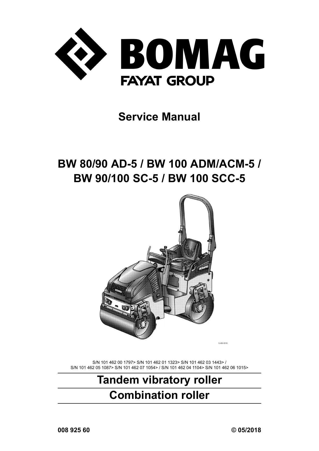
This BOMAG FAYAT Group service manual supports repair and maintenance on the light tandem vibratory rollers and combination rollers listed on the title page:
BW 80 AD-5, BW 90 AD-5, BW 90 AC-5, BW 100 ADM-5, BW 90 SC-5, BW 100 SC-5, BW 100 ACM-5 and BW 100 SCC-5. The publication number is 008 925 60, dated 05/2018. It is written for BOMAG customer service and professionally trained workshop staff and covers deinstallation, dismantling, assembly, installation and component repair where tools and spare-parts supply make that work practical.

Cover serial prefixes printed with the machine family are S/N 101 462 00 1797>, S/N 101 462 01 1323>, S/N 101 462 03 1443>, S/N 101 462 05 1087>, S/N 101 462 07 1054>, S/N 101 462 04 1104> and S/N 101 462 06 1015>. Confirm the plate on the roller before ordering parts or applying a pressure setting from this book.

File Details

  • Manual type: Service Manual
  • Brand / models: BOMAG BW 80/90 AD-5, BW 90 AC-5, BW 100 ADM/ACM-5, BW 90/100 SC-5, BW 100 SCC-5
  • Language: English
  • Page count: 458
  • File format: PDF
  • Document number: 008 925 60
  • Date: 05/2018

Machines and powertrain in this book

All listed machines share a water-cooled three-cylinder Kubota D902 diesel, identified in the assemblies chapter as type D902-E3. Rated output is 15.1 kW (ISO 14396) / 20.2 hp (SAE J 1995) at 3000 min-1, with fixed engine speeds of 2100 and 3000 min-1. Travel speed is 0–10 km/h (0–6.2 mph). Maximum operating weight across the family is 1900 kg (4189 lbs). CECE operating weights in the data tables run from 1550 kg on the BW 80 AD-5 to 1700 kg on several 100-series machines. Drum widths in the dimension tables are 800 mm (BW 80 AD-5), 900 mm (BW 90 AD-5 / BW 90 AC-5), 960 mm (BW 90 SC-5) and 1000–1060 mm on the 100-series variants.

AD and SC machines drive both drums. AC, ACM and SCC combination rollers vibrate the front drum and use rear rubber tires (190/60-15 on BW 90 AC-5; 205/60-15 on BW 100 ACM-5 and BW 100 SCC-5) with four driven wheels on the ACM/SCC machines. Steering is oscillating-articulated, hydrostatic, +/- 33Β° steering angle and +/- 8Β° oscillation. Service braking is hydrostatic; parking brake is hydro-mechanical. The pressurized water sprinkler tank is 100 l; combination machines also carry an 11 l emulsion system. Fuel tank capacity is 30 l diesel.

Exciter data is model-specific. Frequency is 42/63 Hz (2520/3780 vpm) across the family. Amplitude is 0.50 mm on most AD/SC/AC machines and 0.40 mm on BW 100 ADM-5, BW 100 ACM-5 and BW 100 SCC-5. Centrifugal force pairs in the tables include 7/17 kN, 8/17 kN and 8/19 kN depending on drum width and configuration.

Chapters Covered

  • 1 General β€” Introduction; Safety regulations; Maintenance and repair (notes on repair; general notes on maintenance)
  • 2 Technical data β€” BW 80 AD-5; BW 90 AD-5; BW 90 AC-5; BW 100 ADM-5; BW 90 SC-5; BW 100 SC-5; BW 100 ACM-5; BW 100 SCC-5 (each with noise and vibration data); Additional technical data; Terms and basis of calculation; Fuels and lubricants (engine oil, fuel, coolant, hydraulic oil); List of fuels and lubricants
  • 3 Overview of machine β€” General information; Overviews; Electric systems; Hydraulic system; Machine assemblies (diesel engine, oscillating articulated joint, drum)
  • 4 Electric systems β€” Basic principles (measuring method, circuit diagrams, Telemecanique switch, Deutsch DT/DTM plugs, magnetic coil plug); Overview of electric system (driver’s stand old/new, wiring, CAN BUS); Starting with jump wires; Central electrics; Fuse assignment; Description of electrical components; Repairs (generator, starter); Inspection and maintenance work
  • 5 Hydraulic system β€” Basic principles (open/closed circuit, swash plate pump, external gear pumps, reversible external gear motor); Overview of hydraulics; Description of hydraulic components (travel pump A10VG18 HW, drum drive motor MK 04, wheel drive motor MS/MSE, steering valve); Description of hydraulic circuits (travel, vibration, steering, edge cutter, hydraulic cutting tool); Tests and adjustments; Flushing and bleeding (AD/SC and AC machines); Inspection and maintenance work
  • 6 Machine assemblies β€” Diesel engine (overview, Kubota diesel engine, injection valves, fuel injection pump, inspection and maintenance); Oscillating articulated joint (overview, remove/install, repair); Drum (overview, remove/install AD-drum, dismantle, assemble)
  • 7 Troubleshooting β€” Preliminary remarks; Emergency procedures; Towing tandem vibratory roller; Towing combination roller; Electrical systems; Hydraulics; Diesel engine
  • 8 Special tools β€” Hydraulic tests and flushing; Electrics
  • 9 Index
  • Appendix β€” Circuit diagram 368; Hydraulic diagram 289

Complete PDF Bookmark Tree

Complete Bookmarks

The complete bookmarks in the β€œBOMAG BW 80 AD-5 BW 90 AD-5 BW 100 ADM ACM-5 BW 90/100 SC-5 SCC-5 Service Manual 00892560 2018” are as follows:

Table of contentsp. 3
1 ​​General​​p. 7
1.1 ​​Introduction​​p. 8
1.2 ​​Safety regulations​​p. 10
1.3 ​​Maintenance and repair​​p. 29
1.3.1 ​​Notes on repair​​p. 29
1.3.1.1 ​​General repair instructions​​p. 29
1.3.1.1.1 ​​Repair notes for electrics​​p. 29
1.3.1.1.2 ​​Repair notes for hydraulics​​p. 31
1.3.1.1.3 ​​Repair notes for gaskets and mating surfaces​​p. 32
1.3.1.1.4 ​​Repair notes for ball and roller bearings​​p. 34
1.3.1.1.5 ​​Feather keys and keyways​​p. 34
1.3.1.1.6 ​​Repair notes for cotter pins​​p. 35
1.3.1.1.7 ​​Repair notes for screws and nuts​​p. 35
1.3.1.1.8 ​​Strength classes, metric screws and nuts​​p. 35
1.3.1.1.9 ​​Identification of UNF-threads​​p. 37
1.3.1.2 ​​Tightening torques​​p. 37
1.3.2 ​​General notes on maintenance​​p. 43
2 ​​Technical data​​p. 45
2.1 ​​BW 80 AD-5​​p. 47
2.1.1 ​​Noise and vibration data​​p. 49
2.1.1.1 ​​Noise data​​p. 50
2.1.1.2 ​​Vibration data​​p. 50
2.2 ​​BW 90 AD-5​​p. 51
2.2.1 ​​Noise and vibration data​​p. 53
2.2.1.1 ​​Noise data​​p. 54
2.2.1.2 ​​Vibration data​​p. 54
2.3 ​​BW 90 AC-5​​p. 55
2.3.1 ​​Noise and vibration data​​p. 57
2.3.1.1 ​​Noise data​​p. 58
2.3.1.2 ​​Vibration data​​p. 58
2.4 ​​BW 100 ADM-5​​p. 59
2.4.1 ​​Noise and vibration data​​p. 61
2.4.1.1 ​​Noise data​​p. 62
2.4.1.2 ​​Vibration data​​p. 62
2.5 ​​BW 90 SC-5​​p. 63
2.5.1 ​​Noise and vibration data​​p. 65
2.5.1.1 ​​Noise data​​p. 66
2.5.1.2 ​​Vibration data​​p. 66
2.6 ​​BW 100 SC-5​​p. 67
2.6.1 ​​Noise and vibration data​​p. 69
2.6.1.1 ​​Noise data​​p. 70
2.6.1.2 ​​Vibration data​​p. 70
2.7 ​​BW 100 ACM-5​​p. 71
2.7.1 ​​Noise and vibration data​​p. 74
2.7.1.1 ​​Noise data​​p. 74
2.7.1.2 ​​Vibration data​​p. 74
2.8 ​​BW 100 SCC-5​​p. 75
2.8.1 ​​Noise and vibration data​​p. 78
2.8.1.1 ​​Noise data​​p. 78
2.8.1.2 ​​Vibration data​​p. 78
2.9 ​​Additional technical data​​p. 79
2.10 ​​Terms and basis of calculation​​p. 81
2.11 ​​Fuels and lubricants​​p. 82
2.11.1 ​​Engine oil​​p. 82
2.11.1.1 ​​Oil quality​​p. 82
2.11.1.2 ​​Oil viscosity​​p. 82
2.11.1.3 ​​Oil change intervals​​p. 82
2.11.2 ​​Fuel​​p. 83
2.11.2.1 ​​Fuel quality​​p. 83
2.11.2.2 ​​Winter fuel​​p. 83
2.11.2.3 ​​Storage​​p. 83
2.11.3 ​​Coolant​​p. 84
2.11.4 ​​Hydraulic oil​​p. 85
2.11.4.1 ​​Mineral oil based hydraulic oil​​p. 85
2.11.4.2 ​​Bio-degradable hydraulic oil​​p. 85
2.12 ​​List of fuels and lubricants​​p. 86
3 ​​Overview of machine​​p. 87
3.1 ​​General information​​p. 88
3.2 ​​Overviews​​p. 92
3.3 ​​Electric systems​​p. 99
3.4 ​​Hydraulic system​​p. 101
3.5 ​​Machine assemblies​​p. 104
3.5.1 ​​Diesel engine​​p. 104
3.5.2 ​​Oscillating articulated joint​​p. 105
3.5.3 ​​Drum​​p. 107
4 ​​Electric systems​​p. 111
4.1 ​​Basic principles​​p. 113
4.1.1 ​​Measuring method​​p. 113
4.1.2 ​​Understanding circuit diagrams​​p. 118
4.1.2.1 ​​Circuit diagrams​​p. 118
4.1.2.2 ​​Circuit symbols in E-Plan​​p. 125
4.1.2.3 ​​Identification of switch blocks​​p. 128
4.1.3 ​​Telemecanique switch​​p. 129
4.1.4 ​​Deutsch plug, series DT and DTM​​p. 131
4.1.5 ​​Magnetic coil plug​​p. 135
4.2 ​​Overview of electric system​​p. 138
4.2.1 ​​Driver’s stand, old version​​p. 141
4.2.1.1 ​​Control elements​​p. 141
4.2.2 ​​Driver’s stand, new version​​p. 144
4.2.2.1 ​​Control elements​​p. 144
4.2.3 ​​Wiring​​p. 147
4.2.4 ​​CAN BUS overview​​p. 158
4.2.5 ​​Table of fuels and lubricants​​p. 160
4.3 ​​Starting with jump wires​​p. 166
4.4 ​​Central electrics​​p. 167
4.5 ​​Fuse assignment​​p. 172
4.5.1 ​​Central electrics​​p. 173
4.5.2 ​​Main battery fuse​​p. 174
4.6 ​​Description of electrical components​​p. 175
4.6.1 ​​Angle sensor on travel lever, B39​​p. 175
4.6.2 ​​Inductive proximity switch, B63​​p. 177
4.6.3 ​​Switching the vibration on, old version​​p. 178
4.6.4 ​​Switching the vibration on, new version​​p. 179
4.6.5 ​​Switching the pressurized spraying system on, old version​​p. 180
4.6.6 ​​Switching the pressurized spraying system on, new version​​p. 181
4.6.7 ​​Sensor, water in fuel filter, B124​​p. 182
4.6.8 ​​Engine oil pressure monitoring​​p. 182
4.6.9 ​​Coolant temperature monitoring​​p. 182
4.6.10 ​​Level sensor in diesel tank, R03​​p. 183
4.6.11 ​​Charge control light and operating hour meter​​p. 183
4.6.12 ​​Glow plugs, R81, R82 & R83​​p. 185
4.6.13 ​​Engine solenoid, Y13​​p. 186
4.6.14 ​​Instrument cluster, old version​​p. 187
4.6.15 ​​Instrument cluster, new version​​p. 189
4.6.16 ​​Seat contact control​​p. 191
4.7 ​​Repairs​​p. 192
4.7.1 ​​Generator repair​​p. 192
4.7.2 ​​Repair of starter​​p. 196
4.8 ​​Inspection and maintenance work​​p. 202
4.8.1 ​​Maintenance Table​​p. 202
4.8.2 ​​Every 250 operating hours​​p. 202
4.8.2.1 ​​Battery service​​p. 202
4.8.3 ​​As required​​p. 204
4.8.3.1 ​​Battery service during prolonged machine downtimes​​p. 204
5 ​​Hydraulic system​​p. 207
5.1 ​​Basic principles​​p. 209
5.1.1 ​​Open and closed hydraulic circuit​​p. 209
5.1.2 ​​Swash plate principle, pump​​p. 211
5.1.3 ​​External gear pumps​​p. 212
5.1.4 ​​Reversible external gear motor​​p. 215
5.2 ​​Overview of hydraulics​​p. 217
5.2.1 ​​Pump overview​​p. 219
5.3 ​​Description of hydraulic components​​p. 221
5.3.1 ​​Travel pump, A10VG18 HW​​p. 221
5.3.1.1 ​​Variable displacement pumps, A10VG18 HW & A10VG28 HW​​p. 221
5.3.2 ​​Drum drive motor MK 04​​p. 227
5.3.2.1 ​​Radial piston motor​​p. 227
5.3.3 ​​Wheel drive motor, MS/MSE​​p. 232
5.3.3.1 ​​Radial piston motor with multi-disc brake​​p. 232
5.3.4 ​​Steering valve​​p. 236
5.4 ​​Description of hydraulic circuits​​p. 238
5.4.1 ​​Travel circuit​​p. 238
5.4.2 ​​Vibration circuit​​p. 247
5.4.3 ​​Steering circuit​​p. 252
5.4.4 ​​Edge cutter​​p. 259
5.4.5 ​​Hydraulic cutting tool​​p. 260
5.5 ​​Tests and adjustments​​p. 262
5.5.1 ​​Pump overview​​p. 263
5.5.2 ​​Checking the rotation speeds​​p. 264
5.5.3 ​​Pressure tests in the travel circuit​​p. 265
5.5.4 ​​Checking / adjusting the neutral positions of the travel pump​​p. 267
5.5.5 ​​Pressure test in the vibration circuit​​p. 270
5.5.6 ​​Checking the leakage rate of the vibration motor​​p. 271
5.6 ​​Flushing and bleeding​​p. 273
5.6.1 ​​Flushing – general​​p. 273
5.6.2 ​​Flushing schematic for travel system, AD/SC-machine​​p. 276
5.6.3 ​​Travel system, flushing AD/SC-machine​​p. 276
5.6.4 ​​Flushing schematic for travel system, AC-machine​​p. 281
5.6.5 ​​Travel system, flushing AC-machine​​p. 282
5.6.6 ​​Bleeding the travel circuit​​p. 286
5.7 ​​Inspection and maintenance work​​p. 288
5.7.1 ​​Maintenance Table​​p. 288
5.7.2 ​​Checks prior to start up​​p. 288
5.7.2.1 ​​Checking the hydraulic oil level ​​p. 288
5.7.2.2 ​​Checking the hydraulic oil filter element​​p. 289
5.7.3 ​​Every 500 operating hours​​p. 289
5.7.3.1 ​​Checking the hydraulic lines​​p. 289
5.7.4 ​​Every 2000 operating hours​​p. 290
5.7.4.1 ​​Changing hydraulic oil and breather filter​​p. 290
5.7.4.2 ​​Replacing the hydraulic oil filter​​p. 292
6 ​​Machine assemblies​​p. 295
6.1 ​​Diesel engine​​p. 296
6.1.1 ​​Overview of diesel engine​​p. 296
6.1.2 ​​Kubota diesel engine​​p. 300
6.1.3 ​​Check the injection valves​​p. 302
6.1.4 ​​Checking the fuel injection pump​​p. 305
6.1.5 ​​Inspection and maintenance work​​p. 306
6.1.5.1 ​​Maintenance Table​​p. 306
6.1.5.2 ​​Checks prior to start up​​p. 307
6.1.5.2.1 ​​Check the engine oil level​​p. 307
6.1.5.2.2 ​​Checking the coolant level​​p. 308
6.1.5.2.3 ​​Checking the air filter​​p. 308
6.1.5.3 ​​Every 50 operating hours​​p. 309
6.1.5.3.1 ​​Checking, cleaning the air filter, replacing if necessary​​p. 309
6.1.5.3.2 ​​Check fuel lines and clamps​​p. 311
6.1.5.3.3 ​​Checking, cleaning the water separator​​p. 312
6.1.5.4 ​​Every 250 operating hours​​p. 313
6.1.5.4.1 ​​Changing engine oil and oil filter cartridge​​p. 313
6.1.5.4.2 ​​Checking, tensioning, replacing the V-belt​​p. 315
6.1.5.4.3 ​​Checking the air intake lines​​p. 316
6.1.5.4.4 ​​Cleaning radiator and hydraulic oil cooler​​p. 316
6.1.5.4.5 ​​Checking radiator hoses and hose clamps​​p. 317
6.1.5.5 ​​Every 500 operating hours​​p. 318
6.1.5.5.1 ​​Drain the fuel tank sludge​​p. 318
6.1.5.5.2 ​​Change the fuel filter​​p. 319
6.1.5.5.3 ​​Check the anti-freeze concentration and the condition of the coolant​​p. 320
6.1.5.6 ​​Every 1000 operating hours​​p. 320
6.1.5.6.1 ​​Checking, adjusting the valve clearance​​p. 320
6.1.5.6.2 ​​Check the engine mounts​​p. 322
6.1.5.7 ​​Every 2000 operating hours​​p. 322
6.1.5.7.1 ​​Changing the coolant​​p. 322
6.1.5.7.2 ​​Replacing the fuel lines​​p. 325
6.1.5.7.3 ​​Check the injection nozzles​​p. 325
6.1.5.8 ​​Every 3000 operating hours​​p. 326
6.1.5.8.1 ​​Check the fuel injection pump​​p. 326
6.1.5.9 ​​As required​​p. 326
6.1.5.9.1 ​​Checking the engine oil pressure​​p. 326
6.1.5.9.2 ​​Checking the compression​​p. 327
6.1.5.9.3 ​​Checking the thermostat in disassembled state​​p. 328
6.1.5.9.4 ​​Checking the start of commencement​​p. 329
6.2 ​​Oscillating articulated joint​​p. 331
6.2.1 ​​Overview oscillating articulated joint​​p. 331
6.2.2 ​​Removing and installing the oscillating articulated joint​​p. 334
6.2.3 ​​Repairing the oscillating articulated joint​​p. 334
6.3 ​​Drum​​p. 341
6.3.1 ​​Overview drum​​p. 341
6.3.2 ​​Removing and installing the AD-drum​​p. 345
6.3.3 ​​Dismantling the AD-drum​​p. 348
6.3.4 ​​Assembling the AD-drum​​p. 353
7 ​​Troubleshooting​​p. 359
7.1 ​​Preliminary remarks​​p. 360
7.2 ​​Emergency procedures​​p. 361
7.2.1 ​​Actuating the emergency stop switch​​p. 361
7.2.2 ​​Disconnecting the battery​​p. 361
7.2.3 ​​Towing the machine​​p. 361
7.3 ​​Towing – tandem vibratory roller​​p. 362
7.4 ​​Towing – combination roller​​p. 365
7.5 ​​Troubleshooting, electrical systems​​p. 367
7.5.1 ​​Preliminary remarks​​p. 367
7.5.2 ​​Starting with jump wires​​p. 370
7.5.3 ​​Fuse assignment​​p. 371
7.5.3.1 ​​Central electrics​​p. 372
7.5.3.2 ​​Main battery fuse​​p. 374
7.5.4 ​​Trouble shooting "Starter"​​p. 374
7.5.5 ​​Fault detection via instrument cluster, A15​​p. 376
7.5.6 ​​Trouble shooting ECONOMIZER​​p. 377
7.5.7 ​​The machine does not drive​​p. 378
7.5.8 ​​Seat contact control​​p. 380
7.5.9 ​​Check the parking brake​​p. 381
7.6 ​​Trouble shooting, hydraulics​​p. 383
7.6.1 ​​Insufficient hydraulic power​​p. 383
7.6.2 ​​Troubleshooting axial piston pumps​​p. 386
7.6.3 ​​The machine does not drive​​p. 388
7.6.4 ​​Insufficient travel power​​p. 389
7.6.5 ​​Check the parking brake​​p. 391
7.7 ​​Trouble shooting, diesel engine​​p. 393
7.7.1 ​​Engine problems ​​p. 393
8 ​​Special tools​​p. 395
8.1 ​​Special tools, hydraulic system​​p. 396
8.1.1 ​​Special tools, tests and adjustments​​p. 396
8.1.2 ​​Special tools for flushing​​p. 398
8.2 ​​Special tools, electrics​​p. 399
9 ​​Index​​p. 401
Appendixp. 411
A Circuit diagramsp. 413
A.1 Circuit diagram 368p. 413
A.2 Hydraulic diagram 289p. 446

Taken together, the BOMAG BW 80 AD-5 BW 90 AD-5 BW 100 ADM ACM-5 BW 90/100 SC-5 SCC-5 Service Manual 00892560 2018 gives a shop the safety rules, model data, wiring and hydraulic layouts, test ports and pressures, engine service steps, articulation and drum overhaul sequences, towing methods and fault trees needed to keep these compactors working.

Electrical system work

Chapter 4 walks through measurement practice and how to read the circuit diagrams before it names hardware. Driver’s-stand layouts exist in old and new versions. Component coverage includes travel-lever angle sensor B39, inductive proximity switch B63, vibration and pressurized spraying switches (old and new), water-in-fuel sensor B124, engine oil-pressure and coolant-temperature monitoring, diesel-tank level sensor R03, charge control and hour meter, glow plugs R81–R83, engine solenoid Y13, both instrument-cluster generations and seat-contact control. Repair sections cover generator and starter work, including battery-disconnect rules so welding or load-dump events do not destroy control units. Fuse maps list central electrics and the main battery fuse. Jump-start polarity is specified: plus to plus, ground last on, first off. CAN BUS overview notes a diagnostics plug and engine control unit on machines with Tier4f exhaust classification.

Hydraulic circuits, tests and flushing

Travel is a closed circuit driven by a Bosch-Rexroth A10VG18 HW axial-piston swash-plate pump (18 cm3/rev, 72 l/min max flow, 380 bar high-pressure limitation, travel pressure against block 370–410 bar). Charge pressure is 22–27 bar at high idle and 17–25 bar at low idle. Drum drive uses a Poclain MK 04 radial-piston motor (408 cm3/U). Combination-roller wheel motors are Poclain MS 02 (213 cm3/U). Vibration uses a 5.5 cm3/U gear motor. Steering/charge/vibration gear pump displacement is 7 cm3/rev; steering pressure against block is 70–100 bar; vibration start-up pressure is 190–230 bar; operating pressure is soil-dependent at 60–100 bar. The Eaton steering valve is a rotary spool unit.

Test chapters cover rotation-speed checks, travel-circuit pressure tests, travel-pump neutral adjustment, vibration-circuit pressure and vibration-motor leakage (permitted leak-oil rate 1.5 l/min). Separate flushing schematics and procedures exist for AD/SC tandem machines and AC combination machines, followed by travel-circuit bleeding. Maintenance tables call for checks before start-up, work every 500 operating hours and work every 2000 operating hours. Hydraulic oil specified is HV 46 / HVLP 46 (ISO 6743/4 or DIN 51524 part 3), fill quantity 14 l, with an option for ester-based Panolin HLP Synth.46 after a controlled changeover.

Kubota engine, articulation and drum

Engine service includes oil-level and coolant checks, air-filter and fuel-line inspection, water-separator care, 250-hour oil and filter change, V-belt work, radiator hose checks, valve clearance (intake and exhaust 0.145–0.185 mm in the additional data table; adjustment text uses 0.15 mm), engine-mount inspection, 2000-hour coolant change, 3000-hour injection-pump check by authorized personnel, oil-pressure measurement, compression test (factory 36.0–41.0 bar, limit 26.0 bar) and start-of-commencement figures. Injection-valve opening pressure is 140 bar. Low idle is 1200–1400 rpm; high idle 3075–3150 rpm. Engine oil fill is 3.9 l; coolant 9 l (50% ethylene glycol mix, freezing point -37 Β°C at 50%). Fuel specification points to EN 590 / ASTM D975 and ultra-low sulphur fuel where EPA rules apply.

IMAGES PREVIEW

BOMAG BW 80 AD-5 BW 90 AD-5 BW 100 ADM ACM-5 BW 90/100 SC-5 SCC-5 Service Manual 00892560 2018 β€” PDF page 1 preview
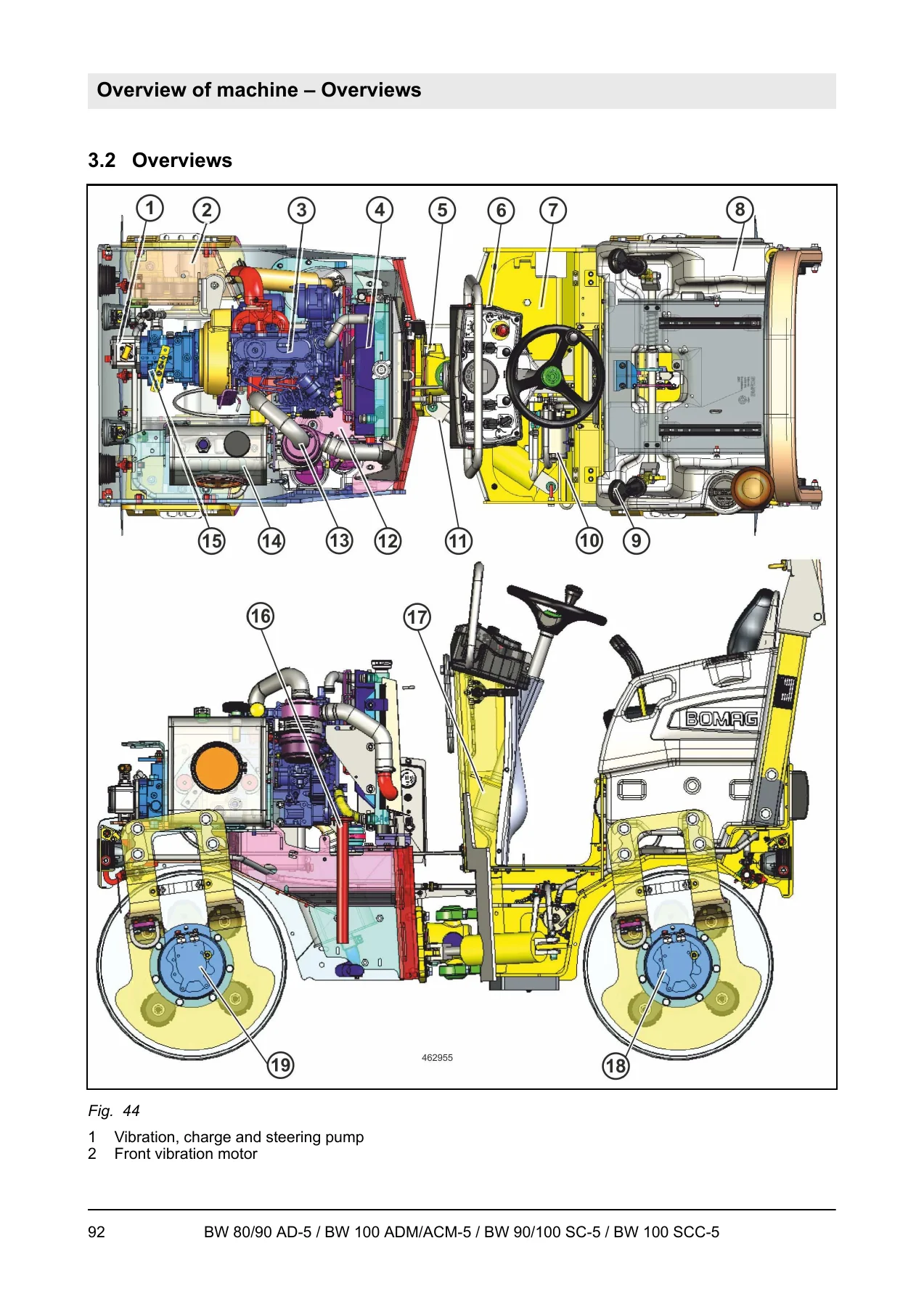
BOMAG BW 80 AD-5 BW 90 AD-5 BW 100 ADM ACM-5 BW 90/100 SC-5 SCC-5 Service Manual 00892560 2018 β€” PDF page 92 preview
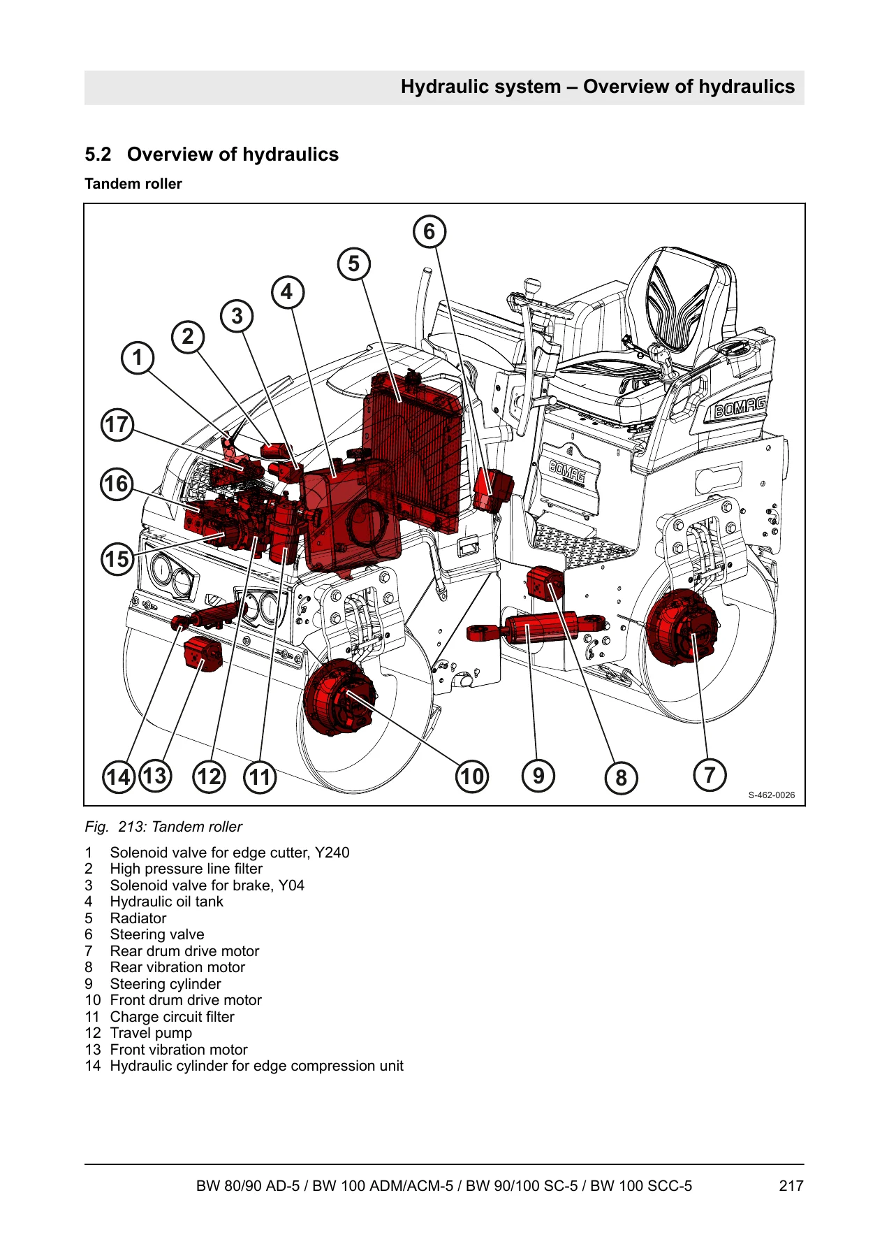
BOMAG BW 80 AD-5 BW 90 AD-5 BW 100 ADM ACM-5 BW 90/100 SC-5 SCC-5 Service Manual 00892560 2018 β€” PDF page 217 preview

The oscillating articulated joint chapter covers overview, removal/installation and repair. The drum chapter shows AD-drum overview, removal and installation, dismantling and assembly. Special-tool lists support hydraulic pressure tests, flushing and electrical work. Appendix circuit diagram 368 and hydraulic diagram 289 close the book.

Safety, towing and troubleshooting

Safety regulations define intended use (bituminous layers and light-to-medium earth or sub-base compaction), prohibited misuse, ROPS inspection, loading, lashing, slope limits (illustrated maximum 20Β° / 36% in static condition), vibration effects on nearby structures, hydraulic-injection injury, battery and fuel handling. Emergency procedures cover the emergency-stop switch, battery disconnect and towing. Towing is limited to 1 km/h and 500 m after the parking brake is released; separate sequences exist for tandem and combination rollers. Electrical fault trees include starter diagnosis, instrument-cluster A15 indications, ECONOMIZER, no-drive conditions, seat contact and parking-brake checks. Hydraulic trees cover insufficient power, axial-piston pump faults and travel complaints. Engine problem tables list poor starting, irregular running, smoke, low oil pressure and related causes.

Use this manual on the job

With the BOMAG BW 80 AD-5 BW 90 AD-5 BW 100 ADM ACM-5 BW 90/100 SC-5 SCC-5 Service Manual 00892560 2018 a technician can set charge and high-pressure gauges on the A10VG18 HW travel pump, adjust pump neutral, measure vibration leakage, flush a contaminated travel circuit on an AD/SC or AC machine, trace a dead start through fuses, Y13 solenoid windings and seat-contact logic, change Kubota D902-E3 oil and valves on the 250-hour and 500-hour intervals, pull an AD drum or repair the oscillating joint, and recover a disabled roller with the correct towing method. Using the printed pressures, speeds, clearances and oil grades avoids guesswork that damages pumps, motors and the three-cylinder diesel.

Download the PDF immediately after payment. No shipping. Open it on a workshop PC, tablet or phone and print the pages you need at the bench.
Reviews

There are no reviews yet.

Be the first to review “BOMAG BW 80 AD-5 BW 90 AD-5 BW 100 ADM ACM-5 BW 90/100 SC-5 SCC-5 Service Manual 00892560 2018”

What Our Customers Say

β˜…β˜…β˜…β˜…β˜… Live reviews from customers
Loading customer reviews...
0
    0
    Your Cart
    Your cart is emptyReturn to Shop
    πŸ›’
    Recently Purchased
    πŸ•’ verified order