
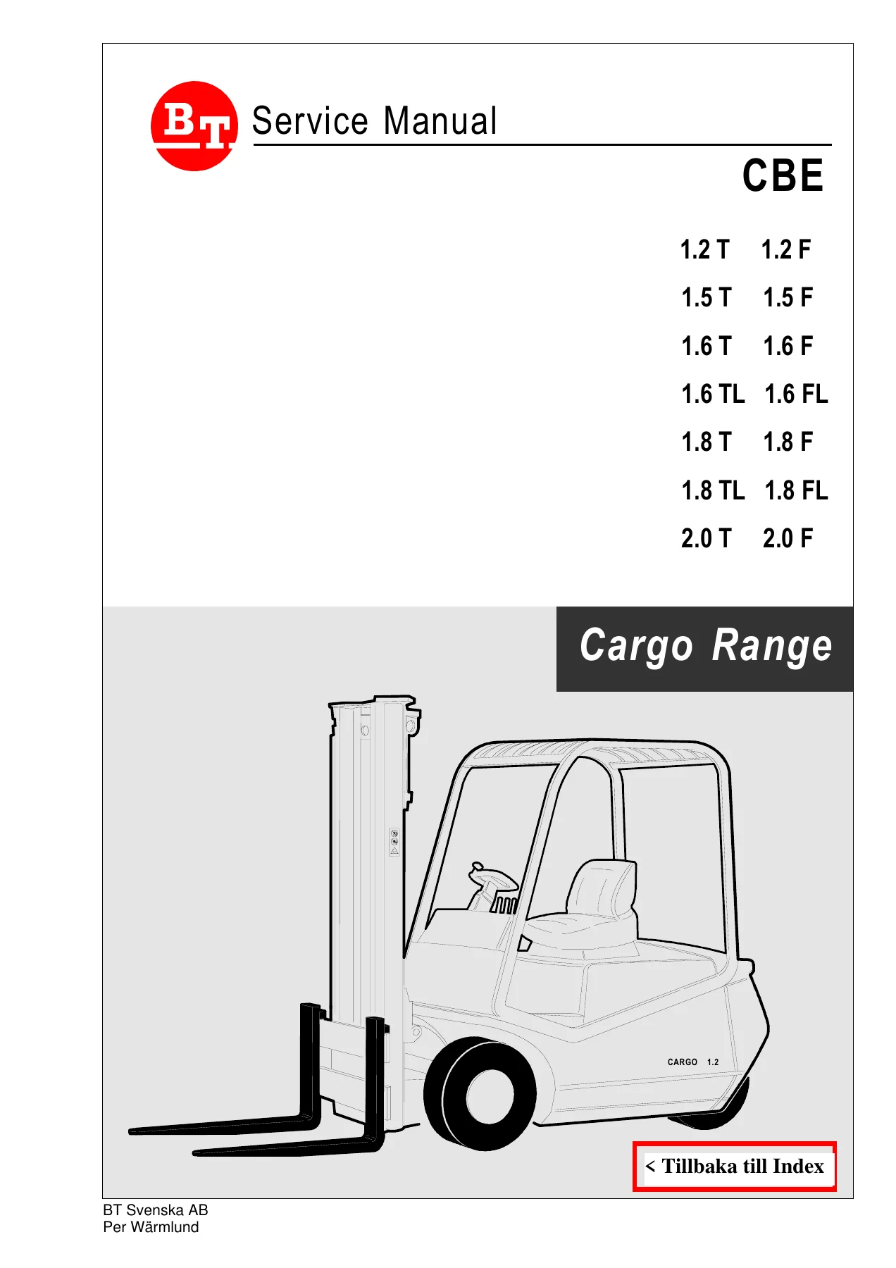
BT CESAB CBE 1.2-2.0 T/F Cargo Electric Forklift Service Manual – PDF Download
Original price was: $54.95.$34.95Current price is: $34.95.
Complete BT CESAB CBE 1.2T through 2.0T/F Cargo electric forklift service manual covering traction and lifting electronics, B1S and HP350 panels, motors, hydraulics, transmission, mast, brakes, wiring schematics, parameter programming, diagnostic codes and maintenance schedules.
Description
BT CESAB CBE 1.2-2.0 T/F Cargo Service Manual
This is the complete service manual for the BT CESAB CBE Cargo range of electric counterbalance forklifts, covering the 1.2T, 1.2F, 1.5T, 1.5F, 1.6T, 1.6F, 1.6TL, 1.6FL, 1.8T, 1.8F, 1.8TL, 1.8FL, 2.0T and 2.0F models. Whether you are a workshop technician, a fleet maintenance engineer or an owner-operator running a CBE truck in daily service, this manual gives you the electrical schematics, mechanical drawings, parameter tables, diagnostic codes and service procedures needed to keep the machine running correctly.
File Details
- Manual type: Service Manual
- Brand: BT / CESAB
- Model range: CBE 1.2T, 1.2F, 1.5T, 1.5F, 1.6T, 1.6F, 1.6TL, 1.6FL, 1.8T, 1.8F, 1.8TL, 1.8FL, 2.0T, 2.0F (Cargo Range)
- Language: English (with multilingual maintenance appendix in Italian, German, French and Spanish; Swedish training documentation also included)
- Page count: 108
- File format: PDF
- Publisher: CESAB S.p.A.
- Document dates shown: November 2000; 2001-05-25
Chapters Covered
- Electronic Panel Characteristics
- Functional Performance and Protections
- General Precautions
- Electrical Motors Characteristics
- Console Functions and Keyboard
- Connection of the Auxiliary Circuit – B1S Unit
- Connection of the Power Circuit – B1S Unit
- Potentiometer Configuration
- Contactor Connection
- Parameter Modification – Unit B1S
- Diagnostic LED Warnings – Unit B1S
- Connection of Electric Circuit HP 350
- Lifting Potentiometer
- Parameter Modifications – Unit HP 350
- Diagnostic LED Warnings – Unit HP 350
- Adjustment Tables
- Dashboard
- Mechanical Section – Explicative Drawings and Diagrams
- Maintenance Appendices and Schedules
- Console Map and Programming
- Electrical Schematics
Electrical Section – Traction and Lifting Electronics
The electrical half of this manual is built around the two ZAPI chopper units used on the CBE Cargo range: the B1S traction controller and the HP 350 hydraulic (lifting) controller. You get full technical specifications for both units, including nominal voltage (48V, 30–60V variation), maximum current ratings (350A + 350A traction; 350A lifting), operating frequency (18 kHz), ambient temperature range (–30 °C to +40 °C), maximum chopper body temperature (85 °C with current derating above 80 °C) and microprocessor logic. The functional performance chapter explains low-speed control, LED diagnostics, console configuration, internal timers, alarm storage (last five alarms with time and temperature), real-time tester readings, arc-less contactor operation, internal coil suppression and high-efficiency switching.
Protections and General Precautions
Protection topics include battery reversal, connection errors, thermal protection, discharged battery behaviour (60% lifting speed reduction), sealed chopper against dust and liquid spray, safety against accidental operation (key + seat micro switch sequence) and safety from uncontrolled movements. The general precautions chapter warns against connecting the chopper to the wrong nominal battery voltage, disconnecting during battery charging, using rectifier outputs or power supplies, handling charged filter capacitors after key-off, and disconnecting the battery before arc-welding on the truck.
Motors and Console
Traction motor: SCHABMULLER P/NO 0057919, 48 V, 108 A, 2160 RPM, 4.2 kW (4.7 kW), service S2, IP 20. Lifting motor: SCHABMULLER P/NO 0058026, 48 V, 1530 RPM, 9.5 kW, lifting pump 17 L/min, service S3 – 13%. The console chapter covers hour meter (one-minute sensitivity, 65,535-hour full scale), alarm display of the last five stored alarms, real-time parameter programming with the machine running, tester mode for analogue and digital values, SAVE and RESTORE of parameter sets, accelerator max stroke programming and the steer table configuration for truck type and pitch.
Auxiliary and Power Circuit Connections – B1S
These pages give the full wiring layout for the B1S unit: brake contactor inputs, key switch +48V feed, ZAPI instrument connection, potentiometer and micro switch inputs, foot-brake micro, seat micro, forward and reverse micro switches, brake contactor outputs, horn, temperature signal light, DC-DC converter output, steering potentiometer supply (7.25 V, 2.2 kOhm, 2.5 V at straight-ahead) and the speed reduction input on I.9. The power circuit diagram shows the left and right traction motors, SH1 and SH2 shunts, direction contactors, field windings, freewheeling diodes and the connection back to the B1S panel.
Potentiometers and Contactor Connection
Drive potentiometer configuration is shown with Green = 12 V, Black = 0–10 V with pedal pressed, Yellow = 0 V, using a 5 kOhm element and a 7 kOhm series resistor. The steering potentiometer is a 2.2 kOhm unit showing approximately 7.4 V at Green, 4.6 V at maximum right-hand steering angle (+90°), 2.5 V straight ahead, 0.4 V at maximum left-hand steering angle (–90°) and 0 V at Yellow. The lifting potentiometer is a 5 kOhm unit with Green = 12 V, Black = 0–10 V when the lifting lever is drawn, Yellow = 0 V. The contactor connection drawing labels the SHL, SHR, A1L, A2L, A1R, A2R, +T and – terminals.
Parameter Modification – Unit B1S
Fourteen traction parameters are documented with their meanings: Acceleration, Invers Braking, Release Braking, Pedal Braking, Cut Back Speed, Brake Cut Back, Curve Cut Back, Compensation, Braking Modulation, Traction IMAX, Creep Speed, Weak Dropout, Speed Limit and Plug Current. Each parameter has an explanation of how it affects machine behaviour, including current levels as a percentage of the chopper maximum.
Diagnostic LED Warnings – Unit B1S
Eight blink-code conditions are listed: 1 flash (watchdog / EEPROM KO), 2 flashes (incorrect start sequence), 3 flashes (VMN low/high on right or left, brake contact open), 4 flashes (pedal wire KO, VACC not OK, bad steering potentiometer), 5 flashes (standby current high, current zero ever), 6 flashes (driver or coil shorted), 7 flashes (thermal protection above 75 °C), 8 flashes (right or left contactor open), 9 flashes (right or left contactor closed, brake contactor closed), continuous flashing (battery discharged) and fixed LED (double running requests). The legend defines R, L, I, VACC, VMN, CON, CONT, CON-COND and DIR.
HP 350 Hydraulic Panel – Circuit, Potentiometer and Parameters
The HP 350 section provides the connection diagram (A1, B1–B8 for console, C1–C3 for lifting potentiometer, D1–D2 for key, E1–E9 for AB POT, 3RD S, 2ND S, MF, BLOCCO, 1ST S, 4TH S, NTIS, NTAS), the hydraulic power schematic with motor M, SH shunt, D1 diode and chopper, the lifting potentiometer wiring (Green = 12 V, Black = 0–10 V, Yellow = 0 V, 5 kOhm), the full parameter list (Acceleration Delay, EV Acceleration Delay, Deceleration Delay, EV Deceleration Delay, Auxiliary Time, I MAX, HYD Speed Coarse, HYD Speed Fine, Hydro Compens, Creep Speed, Weak Dropout, Hydro Time, 1st/2nd/3rd/4th Speed Coarse, Fine and Comp, Min Valve Volt, Max Valve Volt) and the blink-code warning list for the HP 350 (EEPROM faults, incorrect start, no full conduction / VMN low, VACC not OK, current high or zero, driver/coil shorted, thermal protection above 80 °C, continuous flashing for discharged battery).
Adjustment Tables
The B1S adjustment table gives programmed levels 0–9 for Traction IMAX (175–350 A), Acceleration (1.2–4 sec), Cutback Speed (20–100%), Curve Cutback (20–100%), Brake Cutback (32–67%), Invers Braking (15–45%), Release Braking (15–50%), Pedal Braking (15–50%), Weak Dropout (10–80%), Creep Speed (0–9%), Plug Current (10–100%) and Braking Modulation (0–25%). The HP 350 adjustment table gives levels 0–9 for Acceleration Delay (0.15–1.22 sec), EV Acceleration Delay, Deceleration Delay (0.06–0.62 sec), EV Deceleration Delay, I MAX at 400 A and 350 A, Speed Coarse, Speed Fine, Compensation, Creep Speed, Weak Dropout, Hydro Time, Min Valve Volt and Max Valve Volt.
Dashboard
Fifteen dashboard indicators are listed: battery status indicator (2.15 V/cell reset), parking brake, lifting motor temperature, brake oil level, wear indicator for lifting motor brushes, wear indicator for drive motor brushes, hour meter, left-hand drive motor temperature, lifting block due to discharged battery, dead man, traction diagnostic, B1S unit temperature, lifting diagnostic, right-hand drive motor temperature and steering wheel position indicator.
Mechanical Section
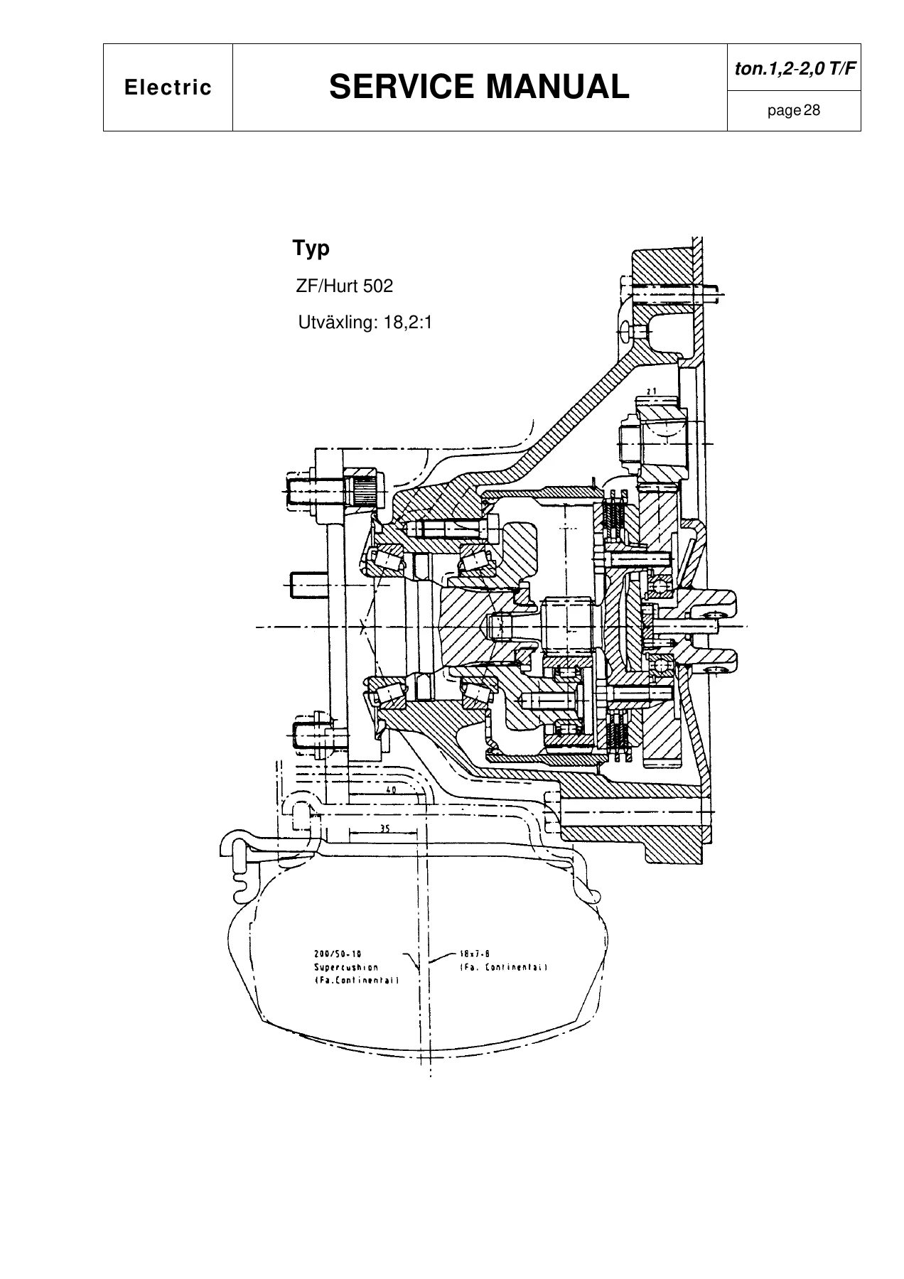
The mechanical half of the manual starts with an exploded cross-section of the ZF/Hurt 502 transmission (ratio 18.2:1, tyre size 200/50-10 Supercushion, 18×7-8). Oil fill and drain plug locations are identified, with AGIP ATF II D specified and a 0.22 L oil volume. The first oil change is after 80 hours, then every 1000 hours. Assembly torque values are given in daNM: 2.3 daNM for the upper bolt, 5.5 daNM for the drive gear, 13.5 daNM for the gearbox-to-frame mounting, and 14 daNM for the wheel nuts. The brake cylinder removal procedure describes removing the three motor screws, inserting a longer screw in the upper hole, sliding the motor back about 2 cm and driving out the pin holding the cylinder. Hydraulic brake system diagrams show the two brake cylinders, the brake fluid reservoir and the pedal linkage.
Hydraulic System, Mast and Lift Cylinder
Hydraulic schematics cover the lift, tilt, sideshift and auxiliary circuits with load sensor lines, pressure relief valve (0.5 bar), flow limiter with 0.7 mm diameter for forward tilt, and a 90 bar setting on the lift circuit. Lift cylinder diagrams show the piston, rod, seals, retaining collars and the 10 cm/10 min maximum fork drop limit. Mast diagrams show the guide pads, rollers, chains, fork positioning pins, retaining collars, and the specification that fork carriage rollers are ungreased roller bearings with Teflon support blocks. The mast adjustment section covers the 1° = 17.4 mm steering angle relationship and the mast tilt angles α and β measured over a 1 m span.
Maintenance Schedules and Appendices
Maintenance tables are provided at 100-hour, 250-hour, 500-hour, 1000-hour and 2000-hour intervals. The 100-hour schedule covers checking the hydraulic system, lift cylinder, mast, chains, rollers and hoses. The 250-hour schedule covers the mast guide pads, carriage, rollers, fork pins, oil filter, hydraulic oil, mast guides and retaining collars. The 500-hour schedule covers motor brushes, motor disconnection, pump motor brushes, hydraulic filters and hydraulic oil. The 1000-hour schedule covers transmission oil. The 2000-hour schedule covers the drive motor, steering system, hydraulic oil, suction filter and mast functions. Multilingual appendices (Italian, English, German) cover tyre pressures, wheel torque, drive unit torque, various torque values, additional running-in maintenance and oil and grease specifications. Oil recommendations include AGIP ARNICA 46 (21 L), AGIP ATF II D (0.22 L), AGIP BRAKE FLUID DOT 4, MOBILGREASE SPECIAL, AGIP ARNICA 22 (21 L) and MOBILTEMP SHC 100 for cold climates and cold storage cells.
Console Map and Programming
The console section gives full menu navigation for both the B1S traction panel and the HP 350 hydraulic panel. For the B1S: Main Menu, Parameter Change, Tester, Save Param, Restore Param, Alarms, Program VACC and Steer Table. For the HP 350: Select Menu 1 Program, 2 Tester, 3 Save, 4 Restore, 5 Alarm, 6 Program VACC. Parameter tables for both units list the setting values that ship as standard. The fault code tables for both panels are repeated in the Swedish documentation with explanations of each blink code. The complete console map is also given as a flow diagram showing connection to the B1S unit, key-on, parameter change, tester, save, restore, alarms, program VACC and steer table.
Electrical Schematics
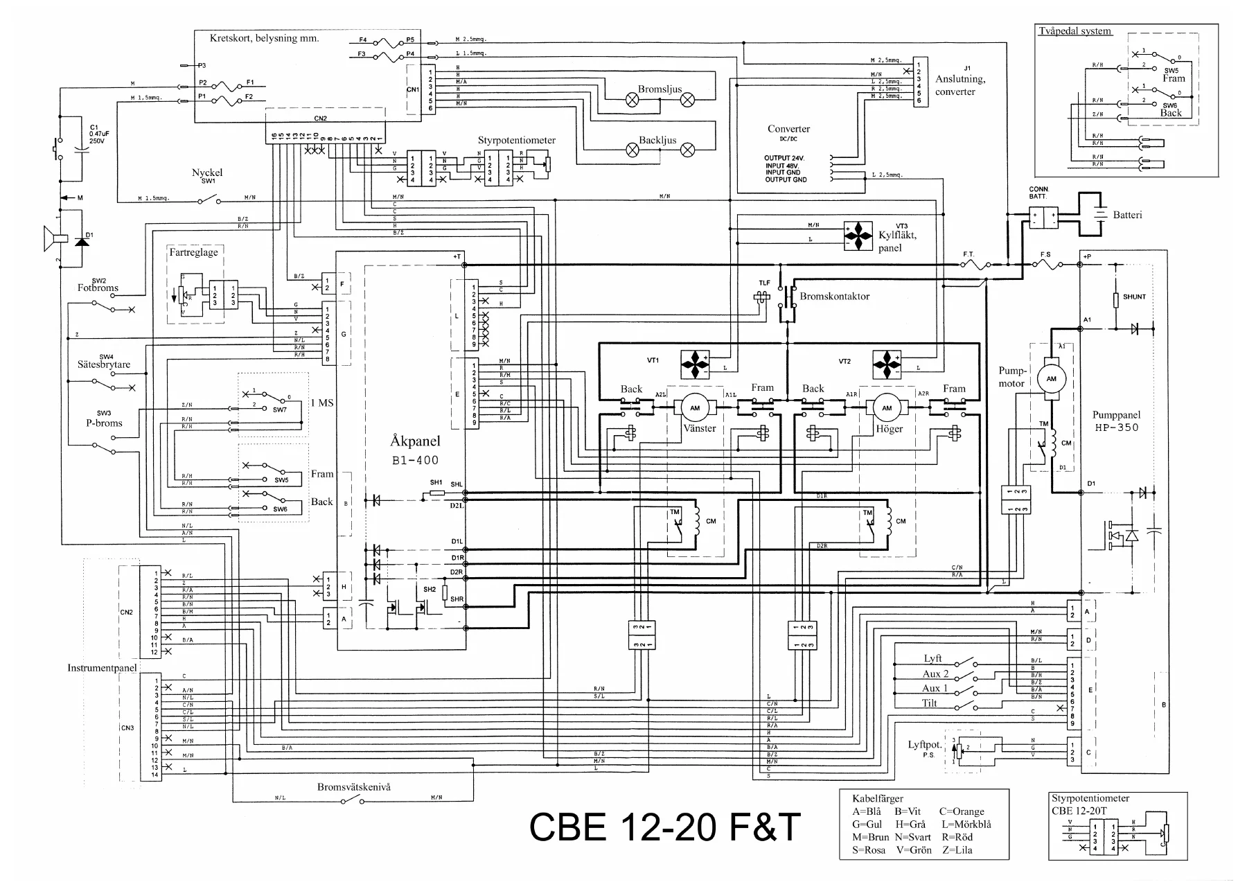
The full electrical schematic for the CBE 12-20 F&T is included, showing the key switch, fuse, battery, DC-DC converter, instrument panel, B1S panel, HP 350 hydraulic panel, left and right traction motors, pump motor, contactors, shunts, potentiometers, micro switches, lights, horn, steering potentiometer and all wiring connections. Separate simplified schematics are provided for key-on, forward running stage 1 and stage 2, backward running, regenerative braking, hydraulic lift, hydraulic tilting and system overview. The legend covers all component codes and wiring colours in English, German, French and Spanish.
Why This Manual Matters
The CBE Cargo is a 48 V electric counterbalance truck with separate traction and hydraulic controllers, and the service information is split between the B1S traction panel and the HP 350 hydraulic panel. Without the correct schematics, parameter tables and blink-code lists, diagnosing a fault on these machines becomes guesswork. This manual gives you the exact voltage thresholds, current limits, temperature trip points, potentiometer values and adjustment levels that the controllers expect. It shows you how the contactors, shunts, freewheeling diodes and field windings are wired, how the two traction motors are driven, how the hydraulic pump and valve drivers are configured, and what each blink code means. For anyone maintaining a CBE 1.2T through 2.0T/F truck, this is the reference document that turns guesswork into a structured diagnostic routine.
What You Can Do With It
- Read and clear stored alarms from the console
- Program and adjust traction parameters (current, acceleration, braking, cutback, compensation)
- Program and adjust hydraulic parameters (acceleration, deceleration, speed, compensation, valve voltage)
- Diagnose blink-code faults on both the B1S and HP 350 panels
- Trace wiring faults using the full system schematic and simplified circuit diagrams
- Set up steering and drive potentiometers correctly
- Configure the console for the correct truck type and pitch
- Service the ZF/Hurt 502 transmission, brakes, mast, lift cylinder and hydraulic system
- Follow the 100, 250, 500, 1000 and 2000-hour maintenance schedules
- Torque fasteners correctly using the daNM values in the mechanical section
- Identify the correct oils and greases for normal and cold-store operation
Delivery
IMAGES PREVIEW
This BT CESAB CBE 1.2-2.0 T/F Cargo service manual is delivered as an instant PDF download. There is no shipping, no waiting and no physical book to lose. The file opens on any device — laptop, tablet or phone — and every page can be printed for use in the workshop. Keep a copy on the service computer, print the schematics for the wall, and have the parameter tables and fault code lists to hand the next time a CBE truck comes in with a traction or hydraulic fault.
Reviews
There are no reviews yet.