
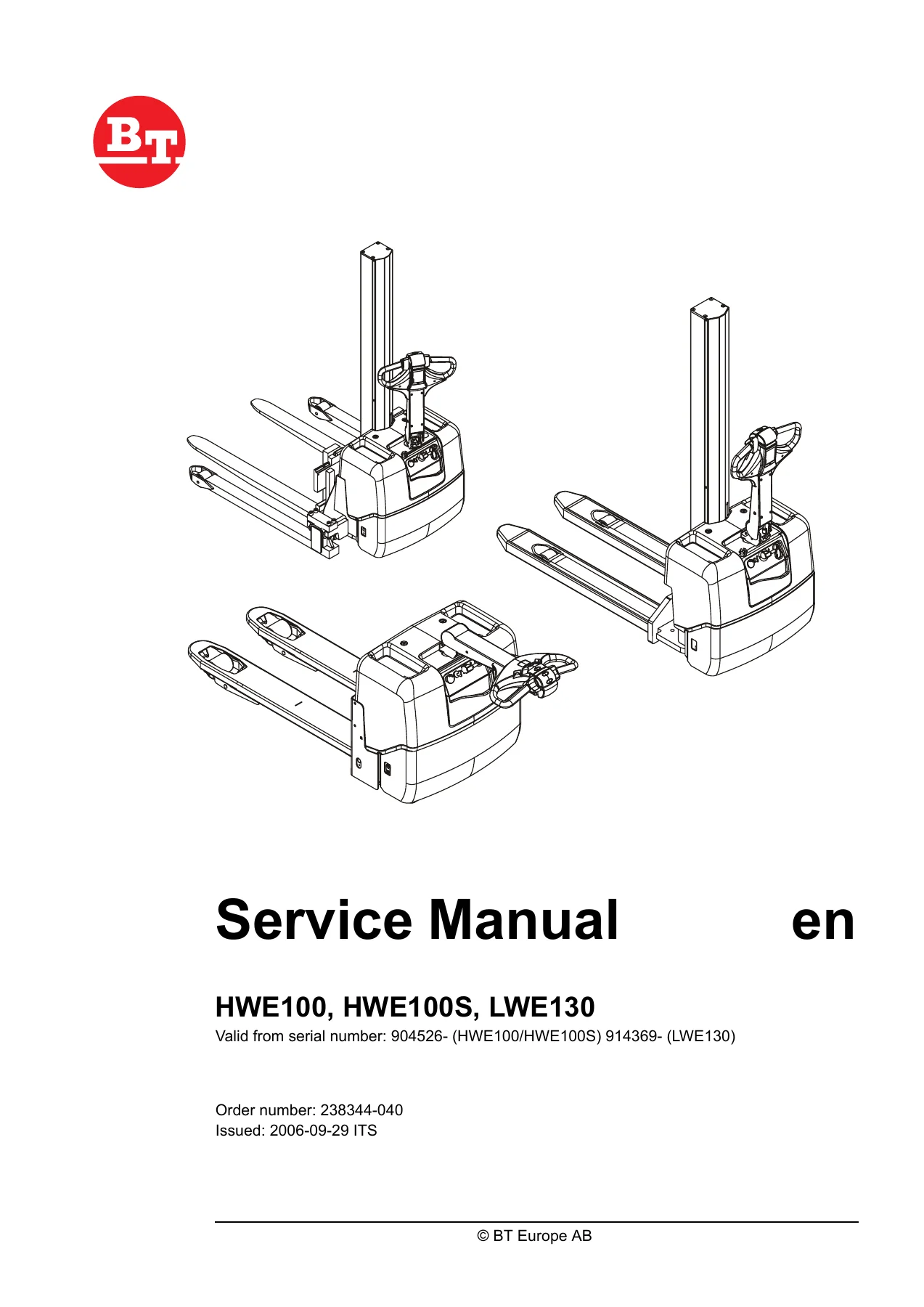
BT HWE100 HWE100S LWE130 Service Manual 2006 – Complete PDF Repair & Maintenance Guide
Original price was: $44.95.$29.95Current price is: $29.95.
Complete BT service manual for HWE100, HWE100S and LWE130 pallet trucks. Covers drive unit, hydraulics, electrical system, brakes, wheels, mast and more. 142 pages, instant PDF download.
Description
File Details
- Manual type: Service Manual
- Brand: BT
- Models covered: HWE100, HWE100S, LWE130
- Language: English
- Page count: 142
- File format: PDF
- Document number: 238344-040
- Date: 2006-09-29
- Valid from serial number: 904526- (HWE100/HWE100S), 914369- (LWE130)
Chapters Covered
- Technical Data
- Maintenance
- Tools
- Chassis (0000)
- Drive Unit/Drive Gear (2000)
- Wheel System (3000)
- Steering System (4000)
- Electrical System (5000)
- Hydraulic System (6000)
- Lift Mast HWE100/HWE100S (7000)
- Accessories (9000)
- Destruction Instructions
Technical Data
The opening chapter sets out the full technical specification for all three truck models. It covers the drive motor (TSL115-16, 0.5 kW, S2 60 min duty cycle), brake unit data (type 891.270.0, 10 Nm brake power, 28 W output, 20.8 ohm coil resistance, 6.75 mm minimum brake disc thickness), and the two-stage wheel gear with its 24.8:1 ratio. Wheel dimensions, axle pressures at rated and unloaded states, tightening torques, hydraulic system output, overflow pressures, pump flow rates, battery capacity, driving speeds with and without load, lift and lowering speeds, power consumption figures, hill-climbing ability, and overall truck weights are all listed in tabular form. A general tightening torque table covers M3 to M24 threads for galvanised and untreated bolts across strength classes.
Maintenance
This chapter establishes the service intervals and the safety framework for all maintenance work. It explains that intervals are based on running times (day shift, two-shift, three-shift calculations) and that the 500-hour service is the standard baseline. Safety regulations cover electrical isolation procedures, hydraulic pressure relief, hot oil precautions, and welding precautions. Cleaning instructions distinguish between external washing, motor compartment cleaning, and electrical component cleaning, each with specific warnings about high-pressure washing and short-circuit risks. Lifting procedures for both truck families are documented with lifting points, centre-of-gravity diagrams, and warnings about overturning. A detailed maintenance schedule table lists every check, lubrication point, and service operation by interval (daily, weekly, 12-month, 36-month), covering chassis, motors, drive gear, brakes, wheels, control system, electrical system, and battery. An oil and lubricants chart specifies hydraulic oil grades (ISO-VG32 for temperatures above -15 degrees C, ISO-VG27.5 below), grease types, and chain oils with their temperature ranges and BT part numbers.
Tools & Connectors
Four sections cover the specialised tools needed for service work. Super Seal, AMP, and Molex connector tool sets are listed with part numbers for fitting and removing pins, sleeves, and secondary locks. The AMP connector section breaks down the PT (Power Timer), JPT (Junior Power Timer), and MPT (Micro Power Timer) families, with 040 series connector diagrams showing cable-side pin arrangements for 2 through 12-pole housings. Grease gun options include single-hand and two-hand models, straight and angled discharge pipes, hose lengths from 450 mm to 1500 mm, and pointed nozzles for recessed nipples. The other tools section covers the driving gear puller, oil cleaning filters, and the hand-held terminal (part 207881) used for communicating with the SEM-X transistor regulator.
Chassis
Support arm procedures differ between the HWE100 and HWE100S. For the HWE100, the chapter documents the bolt joint between chassis and support arms, specifying that bolts must be replaced when the joint is adjusted or arms replaced, with a two-stage tightening sequence to 20 Nm then 200 Nm. Support arm placement diagrams show inner and outer hole positions with width markings. For the HWE100S, the support arm chassis is a separate assembly with adjustable interior widths from 900 mm to 1300 mm. Clamp bolts tighten to 220 Nm. Adjustment and replacement procedures are documented with warnings about lifting only one side at a time.
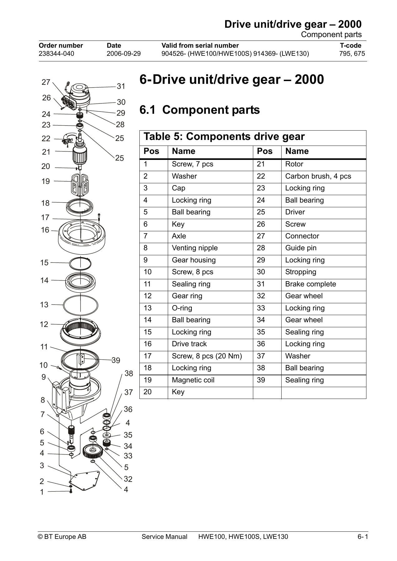
Drive Unit/Drive Gear
The drive unit chapter opens with a complete exploded component view and parts table covering 39 items from screws and washers through the rotor, carbon brushes, ball bearings, gear wheels, sealing rings, magnetic coil, and brake assembly. Service procedures cover dismantling the motor from the truck, inspecting and replacing carbon brushes, replacing the drive wheel (with the note that securing bolts should always be replaced), and cleaning the motor. The brake maintenance section notes that brake discs should be replaced when thickness decreases to 5.5 mm, and provides the procedure for disconnecting cables, removing securing bolts, checking disc wear, and reassembling.
Wheel System
Castor wheel suspension for the HWE100/HWE100S is documented with component diagrams showing the castor wheel, stop screw, washer, nut, holder, and grease nipple. Lubrication points are identified and the castor wheel pressure adjustment procedure is given in detail: the pressure should be 40 plus or minus 10 kg, checked with a 3 mm flat iron bar under the drive wheel. Adjustment involves unscrewing the nut and stop screw, then turning the holder clockwise for lower pressure or counter-clockwise for higher pressure. For the LWE130, the castor wheel components (wheel, fork, bush, ball bearing, greasing nipple) are shown in an exploded view, and lubrication access points are marked on the chassis.
Steering System
The steering chapter covers the tiller arm assembly with a component diagram identifying the handle, screws, washers, tiller arm bracket, gas spring, switch, bundling tie holder, bracket, cylindrical roller bearing, axle, and nut. This is a visual reference for disassembly and reassembly of the steering and control handle assembly.
Electrical System
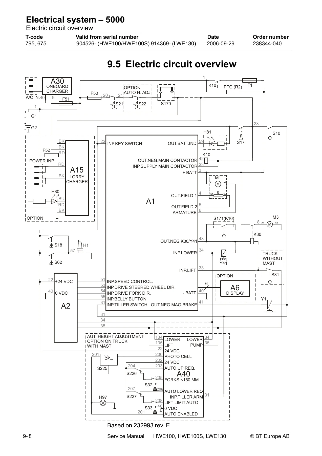
This is the largest chapter, spanning the SEM-X system architecture. It begins with an overview of the electrical system: two 12 V DC traction batteries, a separately excited drive motor controlled by a transistor regulator using pulse width modulation, and a lift unit motor activated by contactor. The firmware version (V1.10) is noted as non-updatable. A comprehensive electric equipment list identifies every component by symbol, function, component type, and diagram reference. Access procedures for the main electric panel are documented with a sequence for swinging out the panel. The chapter includes a full electric circuit overview, symbol list, and wiring diagrams. The automatic height adjustment option has its own section with wiring diagram. Functional descriptions explain operating principles through event-based tables covering battery connection, switch-on, tiller arm lowering, driving in both directions, neutral braking, inversion braking, mechanical brake use, fork lifting, and fork lowering. The SEM-X transistor regulator section covers its general operation, safety precautions, and a 16-pin connector table with signal descriptions. Battery charging options are covered: on-board charging, charge level status indication, and the built-in lorry charger for the LWE130. Troubleshooting covers error code display (both direct LED and hand-held terminal), error history, a comprehensive error code list with causes and solutions, and the TESTER function. Parameters and settings are documented with a parameter list, descriptions for each parameter (acceleration ramp, deceleration ramp, release braking, inversion braking, maximum speed, service counter reset, service warning type, time to next service), procedures for transferring parameter settings between truck and hand-held terminal, and speed potentiometer calibration. Technical data for the SEM-X regulator closes the chapter.
Hydraulic System
The hydraulic chapter covers the compact hydraulic unit used across all three models. For the HWE100/HWE100S, the system consists of a compact unit without a return filter, with a solenoid valve for lowering and a pressure limit valve. Component diagrams identify the lift cylinder, hose breakage valve, non-return valve, flow regulation valve, pressure limit valve, intake filter, pump motor, pump, and lowering valve. For the LWE130, a separate diagram shows the lift cylinder, pressure relief valve, flow control valve, non-return valve, filter, pump motor, pump, tank, and lowering valve. The description explains the lift and lower functions, operating pressure and pressure limitation. Adjustment procedures for the pressure limit valve are given for both truck families, with specific load test criteria (HWE100/HWE130: should lift 1000 kg but not 1100 kg; LWE130: should lift 1300 kg but not 1400 kg). Special tools for adjusting the lock nut and adjuster screw are shown with part numbers.
Lift Mast
The mast chapter covers the main mast, fork carriage, and lift chain system for the HWE100/HWE100S. Mast components are shown in section and exploded views: cover, main lift cylinder, cylinder cover plate, lift chain, roller, mounting bolts, chain guide plate, and mounting bolts. Maintenance covers visual inspection of mast mounting bolts (150 plus or minus 15 Nm if replacement is needed) and lubrication of beam flanges and ribs with specified BT lubricants. Cylinder disassembly and assembly procedures are documented with photographs showing chain sprocket removal and cylinder mounting bolts. Fork carriage maintenance covers play adjustment with shims. The main lift chain system section is extensive, covering chain setting checks, chain inspection criteria (noise, surface rust, rusty links, stiff links, bolt rotation, loose bolts, outline wear, stretching, damage, damaged discs, damaged bolts, dirty chain), cleaning procedures, and lubrication with a temperature-viscosity table recommending specific Klüber and Fuchs products for ambient ranges from below -40 degrees C to above +45 degrees C.
Accessories
The accessories chapter covers the automatic height adjustment option for the HWE100/HWE100S. This system uses a photocell mounted on the mast in an adjustable holder to control lifting and lowering of the forks to maintain a preset height when the sensor detects the load. The holder features an emergency stop switch and an indicator lamp. Controls on the tiller arm allow automatic lifting and lowering. The system includes end position switches for maximum lift height and safety clearance to the ground. A full electrical wiring diagram for the automatic height adjustment is included.
Destruction Instructions
The final chapter provides dismantling instructions organised by C-code for environmentally responsible disposal. Sections cover chassis (iron and steel scrap), hoods and hatches (ABS), electric pump motor (dangerous waste), drive assembly and drive motor (dangerous waste, cables, oil), wheels (vulcanised wheels), tiller arm (cables, metal, electronic scrap), general electrical equipment (batteries as hazardous waste, electronic scrap), hydraulic unit (oil, PP tank, dangerous waste), hydraulic cables and cylinders (oil, iron and steel scrap, oil-contaminated components), and main mast and fork carriage (iron and steel scrap, combustible material). Abbreviations for plastic materials (ABS, PA, PMMA, PP) are defined, along with sorting rules for recyclable plastics, combustible material, iron and steel scrap, composite scrap, oil, oil filters, contaminated parts, batteries, electronic scrap, and cables.
Take Control of Your BT Truck Maintenance
Whether you are a fleet workshop, an independent technician, or a maintenance manager responsible for BT HWE100, HWE100S, or LWE130 pallet trucks, this service manual gives you the information you need to carry out repairs and maintenance correctly. The procedures and specifications in this document are the same ones used by trained service technicians. Using the correct torque values, adjustment procedures, and diagnostic methods prevents costly damage and keeps your trucks operating safely and efficiently.
IMAGES PREVIEW
This BT service manual is delivered as an instant PDF download — no shipping, no waiting. Open it on any device, search for the system you are working on, and print the pages you need for the workshop. The 142-page document includes all the technical data, diagrams, and step-by-step procedures needed to service HWE100, HWE100S, and LWE130 trucks from serial number 904526- (HWE100/HWE100S) and 914369- (LWE130).
Reviews
There are no reviews yet.