
Kalmar DRF 400-450 Error Codes & Diagnostics Workshop Manual – PDF
Original price was: $39.95.$24.95Current price is: $24.95.
Complete error code reference and diagnostic workshop manual for Kalmar DRF 400-450 reachstackers. Covers Volvo TWD1240VE, Volvo TAD1250VE, and Cummins QSM11 engines, Dana and Dana full flow transmissions, CAN bus systems, and all major machine functions with troubleshooting procedures and diagnostic menus.
Description
This Kalmar DRF 400-450 Error Codes and Diagnostics Workshop Manual is the definitive troubleshooting resource for Kalmar DRF 400-450 reachstackers. Published under document number VDRF03.02GB, it delivers the complete error code tables and diagnostic procedures needed to identify, trace, and resolve faults across the machine’s engine, transmission, and control and monitoring systems. Whether you are diagnosing a stop-level engine fault or chasing an intermittent sensor signal, this manual provides the systematic approach Kalmar technicians rely on.
File Details
- Manual Type: Error Codes and Diagnostics Workshop Manual
- Brand: Kalmar
- Model: DRF 400-450
- Document Number: VDRF03.02GB
- Language: English
- Page Count: Approximately 210 pages
- File Format: PDF
Chapters Covered
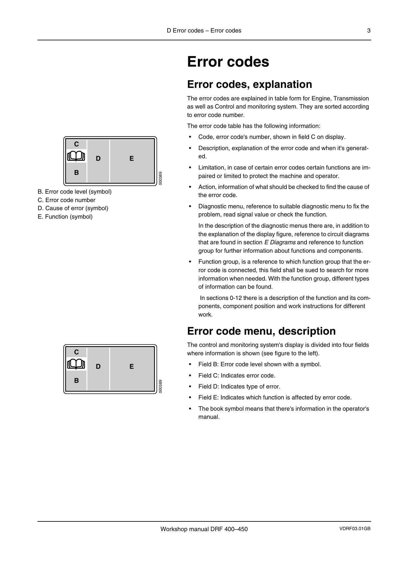
- Error Codes – Explanation: error code table structure, display fields (level, number, cause, function), book symbol reference
- Error Code Levels: Stop (serious malfunction, stop working immediately), Warning (repair as soon as possible), Information (operator notice, stored in service menu)
- Error Code Numbering: Machine (XXX), Engine (XXX/YY), Transmission (XX/YY)
- Reading Out Error Codes: start key position I, service menu navigation, safety menu entry, scrolling active error codes
- Engine Error Codes – Volvo TWD1240VE: fuel pressure sensor, water-in-fuel, oil level, oil pressure, boost pressure, charge-air temperature, coolant temperature, coolant level, crankcase ventilation, battery voltage, intake air temperature, oil temperature, engine rpm, preheating relay, control unit faults, injector faults by cylinder
- Engine Error Codes – Volvo TAD1250VE: same parameter coverage with TAD1250VE-specific connector references and limitations
- Engine Error Codes – Cummins QSM11: speed sensor, accelerator pedal, water-in-fuel, oil pressure, boost pressure, intake air temperature, charge air temperature, air pressure sensor, coolant temperature, coolant level, output imbalance, battery voltage, oil temperature, wastegate solenoid, rpm sensors, speed limitation, control unit internal faults, preheating relay, fuel cut-off solenoid, fan connection, injector faults by cylinder, engine brake solenoids, oil level
- Transmission Error Codes – Dana: control unit memory errors, oil pressure sensor faults (1 through 4), battery voltage, reference voltage, drum rpm sensor, turbine speed, system pressure, gear selector direction, seat direction change, gear selection, gear ratio, torque converter temperature, accelerator pedal signal, speed inputs, max torque inching, top speed limit, 4WD/2WD selector, Low/High selector, oil pressure sensor short/open circuit, oil temperature sensor, analogue input signals 3/5/7/8, pressure sensor gear 2/4, drum rpm, output shaft rpm, engine rpm, turbine rpm, solenoid valve faults (VFS forward, VFS 2/4, VFS reverse, VFS 1/3, RSP Drive, VFS 2/4, VFS 1/3), software errors, system errors, gear direction faults, duplicated signals, configuration errors, calibration procedures
- Transmission Error Codes – Dana Full Flow: same parameter coverage with full flow-specific components including B6067, B6069, B7520, B7580, B7530, B7510, B7660, Y6300, Y6067, Y6069, Y6066F, Y6066R, Y6074, Y6075
- Control System Error Codes – Machine: communication errors with attachment control units (D791-1 through D791-4), frame control units (D797-R, D797-F, D797-O), KID control unit (D795), cab option control unit (D790-3), CAN bus segment wiring faults 1 through 8, accelerator pedal calibration, transmission control unit communication, engine control unit communication, setup file read errors, cab fan power feed, software download interference, cab control unit power supply, 5V reference voltage, emergency stop switch feedback, parking brake switch, wiper motor circuits, rotating beacon, working light circuits, cab fan motor, recirculation actuator motor, water valve, damper motor, washer motor, indicator lamp circuits, background lighting, tilt lock LED, levelling lock LED, seat heater relay, extra working light relay, hour meter and air suspension seat relay, ignition voltage relay, emergency stop relay, horn relay, pressure switch air conditioning, actuating motor, accelerator pedal signal, control lever signals (lift/lower, extension, rotation, tilt), steering lever/mini-wheel signals, water valve signal, cab temperature sensor, outside temperature sensor, outlet fan temperature sensor, refrigerant temperature sensor, frame front/rear/option power feeds, emergency stop voltages, 5V reference voltages, cooling fan brake fluid, high beam lamps, low beam lamps, solenoid valves (boom up/down/in/out, blocking lift left/right, regeneration lift right/left, parking brake), direction indicator lamps, position light lamps, NC/NO switch reference voltage, sensor hydraulic pressure lift cylinder left/right (C+ and C-), boom angle sensor, boom length sensor, brake oil temperature, brake oil temperature sensor, load curve, overload protection, frame rear power feeds, 5V reference to analogue sensors, cooling fan hydraulic oil, working lights boom left/right front, reversing lights left/right, steering axle load sensors, position sensor boom length, regeneration extension solenoid, blocking extension solenoid, reversing warning device, top hydraulics solenoid, brake light left/right, position light left/right rear, rear light left/right, direction indicator left/right rear, steering axle load sensor signal difference, pump unloading solenoid, boom angle sensor signal, boom length sensor signal, AC compressor clutch, starter motor relay (Cummins only), hydraulic oil temperature, hydraulic oil temperature sensor, fuel level sensor, frame option power feeds, cab forward/up solenoid, cab backward/down solenoid, steering left/right solenoids, support jacks up/down solenoids, cab tilt up/down solenoids, hydraulic pump disengagement solenoid, 24V reference voltage for support jack position sensors, cab lift position sensor, cab forward/up solenoid feedback, cab backward/down solenoid feedback, steering left/right solenoid feedback, attachment control unit power feeds, attachment working lights, attachment rotation solenoids, spreading solenoids, side shift solenoids, twistlock solenoids, tilt lock solenoids, voltage feed to attachment position sensors, indicator lights (open twistlocks, alignment, locked twistlocks), rotation solenoid feedback, spreading solenoid feedback, twistlock sensor alignment, attachment option power feeds, levelling solenoids, tilt solenoids, levelling lock solenoids, attachment left jack pair power feeds, working lights left lifting jacks, levelling lock solenoids, operating position solenoid, levelling solenoid, front knee in/out solenoids, rear knee in/out solenoids, lowering front jack solenoid, front jack up solenoid, lowering rear jack solenoid, rear jack up solenoid, indicator lights (alignment lifting jack right front/rear, left front/rear), clamp/release solenoids, voltage feed to position sensors, levelling solenoid feedback, attachment right jack pair power feeds, working lights right lifting jacks, operating position solenoid, tilt out/in solenoids, front knee in/out solenoids, rear knee in/out solenoids, lowering front jack solenoid, front jack up solenoid, lowering rear jack solenoid, rear jack up solenoid, indicator lights (front jacks raised/lowered, clamping position front/rear), clamp/release solenoids, voltage feed to position sensors, KID control unit power feeds, CAN buffer messages, service indicator
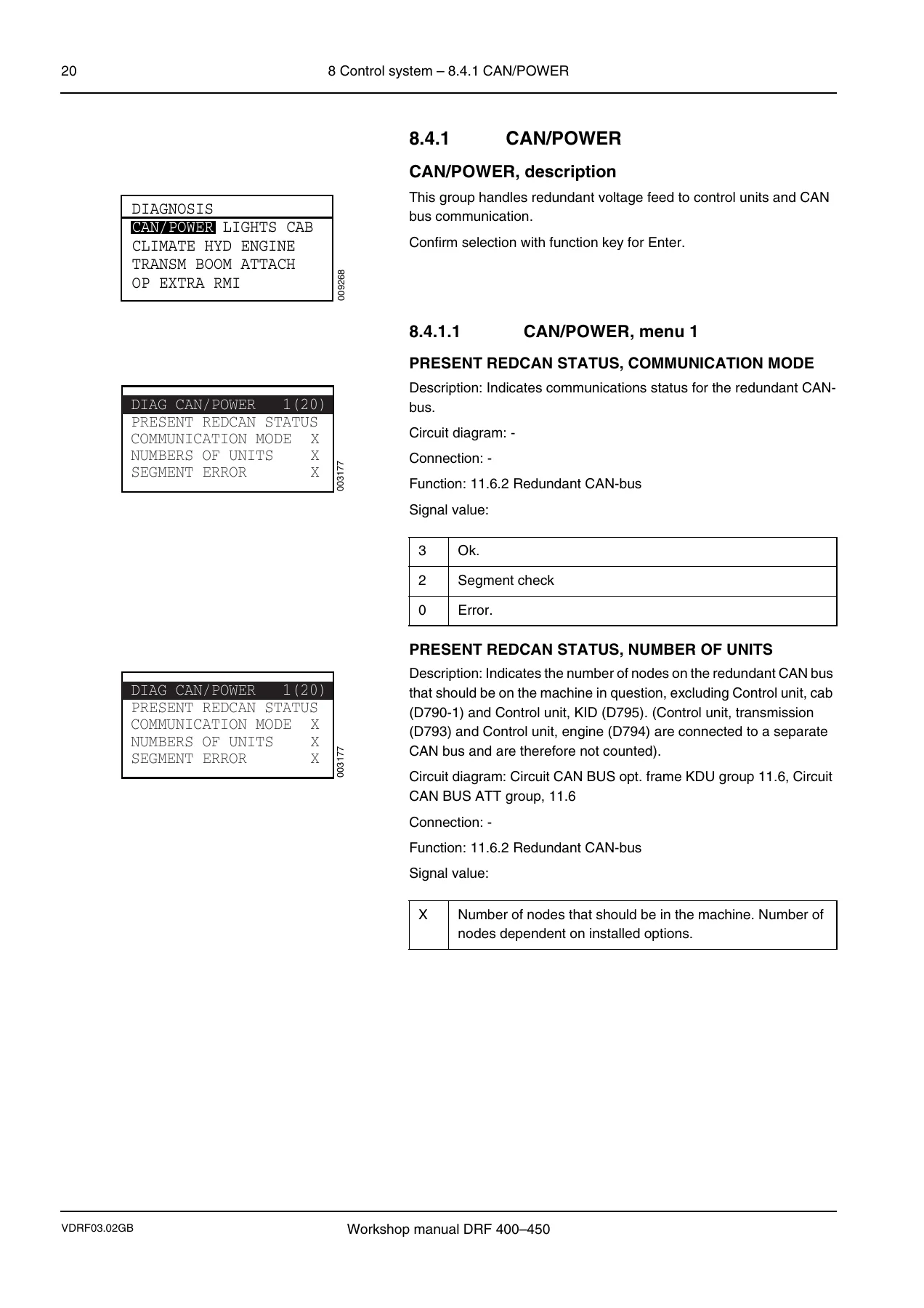
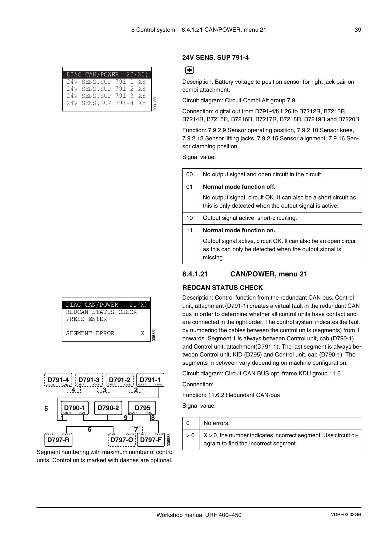
- Diagnostic Tests – CAN/POWER: redundant CAN status, communication mode, number of units, segment error, drive-train CAN bus status for engine and transmission, ignition status, relay status, emergency stop switch, feedback, relay K3009-2, cab power, 5V reference, 24V sensor supply, redundant power feeds, emergency stop power, frame front/rear/option power feeds and sensor supplies, transmission power/ignition/sensor supply, attachment control unit power feeds, 24V sensor supplies for attachment and jack pairs, REDCAN status check
- Diagnostic Tests – LIGHTS: working light cab switch and output, working light attachment switch and output, optional output, working light boom switch and output, optional output, main light switch, side/front/side rear/rear output signals, headlight switch, headlights, dimmed headlights, hazard switch, flasher switch, hazard/flasher front and rear output signals, rotating beacon switch and output, brake light switch, reverse light signal, brake light output, reverse light output, back-up alarm
- Diagnostic Tests – CAB: washer switch, washer output front, washer output rear/roof, front wiper switch/output/feedback, rear wiper switch/output/feedback, roof wiper switch/output/feedback, horn switch/output, switch joystick, buzzer, seat switch, alarm, overload protection, fuel sensor value, fuel processor, seat heater switch/output, automatic lubrication chassis output, automatic lubrication attachment output
- Diagnostic Tests – CLIMATE: required temperature, present temperature, water valve feedback, temperature coil, temperature coolant, temperature ambient, temperature de-ice, pressure switch, optional door switch, water valve input signal, draught valve input signal, required temp input signal, required draught input signal, required fan speed input signal, fan speed output signal, recirculation output signal, compressor output signal, water valve output clockwise/counter-clockwise, draught valve output clockwise/counter-clockwise
- Diagnostic Tests – HYD: hydraulic oil temperature, hydraulic oil fan, brake coolant oil temperature, brake coolant oil fan, pressure lifting cylinder C- and C+, pressure switches (brake pressure, brake light pressure, declutch pressure), parking brake switch, feedback switch, valve, pressure to attachment valve
- Diagnostic Tests – ENGINE: accelerator, required speed PROC, required speed RPM, engine speed EDC, engine speed TCU, present torque, required torque, present torque at RPM, preheat switch, crank engine switch, D+, preheat output, crank engine output, oil pressure, boost pressure, oil level, oil temperature, coolant temperature, intake main temperature, EDC error number, SPN, FMI, fuel consumption momentarily l/h
- Diagnostic Tests – TRANSM: brake pedal, declutch switch, declutch pressure switch, forward/reverse/shift mode switches, forward/reverse/gear present values, operating state (auto/manual mode, warning, operating mode), shift in progress, fault, old fault, drum speed, output speed, engine speed, turbine speed, output status (RSP drive, 2/4 VFS selection, 1/3 VFS selection, FWD selection, REV selection, 2/4 selection, 1/3 selection), FWD/REV/2/4/1/3 supply, FWD/REV/2/4/1/3 feedback, analogue outputs, present sensor input (press feedback, transmission temp, cooler temp, 2/4 pressure, 1/3 pressure, transmission temp, converter temp out), axle ratio, radius, speed limit, actual error area, type, number of occurrences, time ago, converter status (torque impeller, torque turbine)
- Diagnostic Tests – BOOM: boom up/down input signals, boom in/out input signals, block valves up/down/in/relieve pressure in, boom high speed up/out, output boom up/down/in/out reference/required value/feedback, boom low speed up/down/in/out input signals
- Diagnostic Tests – ATTACH: rotation CW/CCW input signals, tilt in/out input signals, side shift input signals, pistol input signal, 30/35 stop input signal, lock/unlock twistlock input signals, bypass height input signal, tilt locking input signal, levelling locking input signal, auto 20′-40′ input signal, low speed 20/40 input signal, extension 60cm input signal, alignment front/rear input signals, locked/unlocked twistlock input signals, side shift left/right output signals, lock/unlock twistlock output signals, indicator locked/unlocked twistlock output signals, indicator alignment output signal, rotation CW/CCW output reference/required value/feedback, spreader out/in output reference/required value/feedback, tilt locking 1/2 output signals, buzzer auto 20-40 output signal, tilt out/in output reference/required value/feedback, lock levelling 1/2 output signals, levelling right/left output reference/required value/feedback, rotation stop switch/sensor stop input signals, length to container input signal, damp down input signal
- Diagnostic Tests – OP: steering axle input signal, boom angle input signal, extension input signal, bypass input signal, lift cylinder C- and C+ input signals, boom angle input signal, boom extension input signal, allowed load, present load, load steering axle, load centre, boom angle, boom extension, boom height, boom height nose
- Diagnostic Tests – EXTRA (COMBI): front/rear leg up/down switches, clamp in/out switch, clamping sensors front/rear legs, alignment sensors front/rear legs, end position sensors front/rear knee and leg, legs in drive position, indication lamps alignment front/rear, indication lamps clamp front/rear, indication lamps front legs up/down, front/rear legs down/up output signals (knee, legs), sequence mode front/rear, clamp in/out output signals, drive position output signal, force control valve selection
- Diagnostic Tests – EXTRA (SLIDING-CAB): forward/reverse/opened doors switches, low speed input signal, cab down (lift) input signal, output forward/reverse reference/required value/feedback
- Diagnostic Tests – EXTRA (SUPPORT-JACKS): up/down switches, up/down input signals, output valve S-J up/down, indicator lamp down
- Diagnostic Tests – EXTRA (EL-STEERING): signal 1 and 2 input signals, on/off/forward/reverse switches, horn input signal, steer wheel cut off input signal, output steering left/right reference/required value/feedback
- Diagnostic Tests – RMI: MIU software version, MIU time, signal quality (GSM, GPRS, WLAN, RADIO, SMS, UNS.DATA), error, error valid, active error
- Initiation Procedures: boom lift/lower/extension start and end currents, lift speed at F/R, option load centre limit, option height limit, attachment rotation CW/CCW start and end currents, tilt start and end currents, levelling start and end currents, spreader out/in start, end, and damping values, option damp boom down top/bottom lift distances, sliding cab forward/reverse start, end, and damping values, steering lever character, break points BP1/BP2/BP3, PROC reduction at BP2/BP3, steering right/left start and end currents, drive-train start in 2nd, vehicle speed F-R, engine speed F-R, engine speed N-DIR, engine speed kickdown 1st, vehicle speed declutch, option speed limit, option highest gear at speed limit, option engine shut down at idle, F-R without engine speed reduction
- Calibration Procedures: weight indicator fixed scale calibration (model year -2008), weight indicator dynamic scale calibration, lever steering calibration (centre, left, right positions), accelerator pedal calibration (release and full throttle), transmission calibration (gearbox warm-up, gearbox tuning with clutch/phase/action/sub-phase/status codes)
This Kalmar DRF 400-450 Error Codes and Diagnostics Workshop Manual is far more than a fault-code list. It is a complete diagnostic decision-support system that maps every error code to its cause, affected function, and the specific diagnostic menu needed to read live signal values, verify circuit integrity, and confirm the repair. The manual covers three engine alternatives – Volvo TWD1240VE, Volvo TAD1250VE, and Cummins QSM11 – and two transmission alternatives, Dana and Dana full flow, with component-level detail for each variant. Every error code entry includes the code number, J1587/SPN-FMI cross-reference, description, limitation (how the machine protects itself), action (what to check), connections and components (specific control unit pins and component designations), and diagnostic menu reference. The diagnostic menu section then walks through every menu group – CAN/POWER, LIGHTS, CAB, CLIMATE, HYD, ENGINE, TRANSM, BOOM, ATTACH, OP, EXTRA, and RMI – showing exactly which signal is being read, what the values mean, and how to interpret them. For any technician responsible for maintaining or repairing a Kalmar DRF 400-450, this manual turns a cryptic error code into a clear, step-by-step repair path.
What This Manual Enables You To Do
With this Kalmar DRF 400-450 Error Codes and Diagnostics Workshop Manual in hand, you can confidently diagnose and repair the full range of faults that the DRF 400-450 can generate. The error code tables cover every engine fault from fuel pressure sensor failures to injector circuit faults on all six cylinders, every transmission fault from oil pressure sensor errors to solenoid valve failures and clutch calibration issues, and every control system fault from CAN bus communication errors to individual lamp, motor, and solenoid circuit failures. The diagnostic menus give you live signal values, circuit status indicators, and required/feedback comparisons so you can verify sensor operation, check wiring integrity, and confirm that a repair has actually resolved the problem. The initiation and calibration procedures let you set start and end currents for hydraulic functions, calibrate the weight indicator, steering lever, accelerator pedal, and transmission, and restore proper machine behaviour after component replacement or control unit changes. This manual is essential for any workshop that services Kalmar DRF 400-450 reachstackers, whether you are troubleshooting a stop-level engine shutdown, a warning-level transmission fault, or an information-level bulb failure.
When a machine is down, accurate information is the difference between a quick fix and a costly guessing game. The Kalmar DRF 400-450 Error Codes and Diagnostics Workshop Manual eliminates guesswork by giving you the exact diagnostic menu for each code, the specific pins and components to check, and the signal values that tell you whether a component is working or not. The result is faster diagnosis, correct repairs, and fewer return visits.
IMAGES PREVIEW
Instant PDF Delivery
This Kalmar DRF 400-450 Error Codes and Diagnostics Workshop Manual is delivered as a PDF file immediately after purchase. There is no shipping, no waiting, and no physical media to lose or damage. The file can be viewed on any device – laptop, tablet, or smartphone – and printed pages can be taken directly to the machine. Whether you need to look up a single error code or work through a complete diagnostic procedure, the information is available instantly and permanently. Add this manual to your workshop library today and make every DRF 400-450 fault a solvable problem.
Reviews
There are no reviews yet.