★ TRUSTED BY 321,897+ PROFESSIONALS WORLDWIDE
🏒
Trusted Business
Verified & Licensed
πŸ›‘οΈ
Virus Free Files
100% Safe Downloads
πŸ”’
Secure Payment
SSL Protected
⚑
Instant Delivery
Available Immediately
Sale!

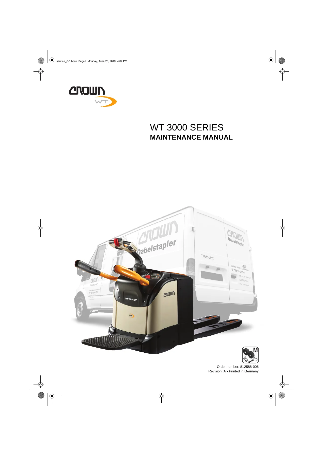
Crown WT 3000 Series Pallet Truck Maintenance Manual – WT 3020, WT 3040, WT 3060

Original price was: $29.95.Current price is: $18.95.

Complete Crown WT 3000 Series maintenance manual covering WT 3020, WT 3040 and WT 3060 electric pallet trucks. Includes hydraulic system, drive unit, electrical system, brake system, steering, lifting mechanism and cylinder service procedures.

⚑
Instant PDF Download
Available immediately
πŸ’Ύ
Save to Your Device
Download & keep forever
πŸ›‘οΈ
Antivirus Scanned
100% virus-free
🌍
Trusted Worldwide
175,000+ customers

Description

Crown WT 3000 Series Maintenance Manual

This Crown WT 3000 Series Pallet Truck Maintenance Manual provides comprehensive maintenance and repair guidance for the WT 3020, WT 3040 and WT 3060 electric pallet trucks. Whether you are servicing a WT 3020 with mechanical steering, a WT 3040 in either mechanical or electric steering configuration, or a WT 3060 with electric steering, this manual delivers the procedures, specifications and troubleshooting detail needed to keep these machines operating correctly. The document is divided into clearly indexed sections covering lubrication and adjustment, hydraulic systems, drive units, electrical systems, brake systems, steering, lifting mechanisms, cylinders, platforms and schematic diagrams.

File Details

  • Manual type: Maintenance Manual
  • Brand: Crown
  • Models covered: WT 3020, WT 3040, WT 3060
  • Document number: 812588-006
  • Language: English
  • Page count: Approximately 464 pages
  • File format: PDF
  • Publication references: Rev.1 02/2009, Rev.1 03/2009, Rev.1 04/2009

Chapters Covered

  • Introduction
    • Important Information
    • Manual structure
    • Text mark-ups in the manual
    • Service personnel qualification
    • Ordering spare parts
    • Truck Data Number
  • Safety
    • Safety Notices
    • Basic Safety Notices
    • Organisational measures
    • Personal safety equipment
    • Protecting the hazardous area
    • Hazards from stored energy
    • Repair work
    • Restoring the truck to service after repair work
    • Cleaning work
    • Handling batteries
    • Warning and instruction decals on the truck
    • Lifting gear and slings
    • Environmental protection
  • Lubrication & Adjustment
    • Lifting the Truck
    • Towing the Truck
    • Jacking up the Truck
    • Transporting the Truck
    • Storing the Truck
    • Restoring the Truck to Service
    • Cleaning the Truck and Components
    • Recommended Lubricants and Consumables
    • Planned Maintenance
    • Maintenance Schedule
    • Finger Guard
    • Torques
  • Hydraulic System
    • Replacing the Hydraulic Unit
    • Replacing the Hydraulic Oil and Bleeding the System
    • Relief Valve Replacement and Adjustment
    • Drift Test
    • Hydraulic System Troubleshooting
  • Drive Unit
    • Components
    • Replacing the Drive Wheel
    • Changing the Gear Oil
  • Electrical System
    • Electrical Components
    • Software Versions
    • Menu Structure
    • Event Codes
    • Input Signals
    • Platform and Side Restraint Logic
    • Analyzer Menu
    • Calibration
    • Software Parameter Settings
    • Servicing and Replacing the Control Modules
    • Control Module PMT Test
    • General DC Motor Maintenance Instructions
    • Traction Motor (M1)
    • Pump Motor (M2)
    • Steer Motor (M3)
    • Battery Information
    • Battery Discharge Indicator (BDI)
    • Repairing Contactors
    • Modifications
  • Brake System
    • Components and Operation
    • Servicing the parking brake
    • Replacing the Parking Brake
    • Testing the Braking Distance
  • Steering
    • Replacing the SAHS Sensor
    • Repairing Control Handle Return Springs
    • Repairing the Control Handle
  • Lifting Mechanism
    • Checking and Adjusting the Fork Height (Lowered)
    • Adjusting the Lift Limit Cutout and Fork Height (Raised)
    • Forks
  • Cylinders
    • General
    • Tools
    • Rod Seal Removal and Assembly
    • Cylinders and Cylinder Operation
    • Replacing the Lift Cylinders
    • Repairing Lift Cylinders
    • Replacing the Traction Cylinder
    • Repairing the Traction Cylinder
  • Platform
    • Adjusting the Folding Platform Switch
    • Replacing the Folding Platform Springs
  • Schematic Diagrams
    • Wire Colour Code
    • General contact symbol abbreviations
    • Electrical wiring diagrams
    • Connectors, standard
    • Connectors, options
  • Hydraulic Schematic
    • Hydraulic Symbols

The Crown WT 3000 Series maintenance manual is a complete workshop reference for technicians maintaining these electric pallet trucks. It opens with the truck data number system, then walks through safety procedures, lifting and jacking methods, lubrication schedules and standard torque values before moving into system-specific service chapters. The hydraulic section covers unit replacement, oil changes, relief valve adjustment and drift testing. The drive unit chapter addresses drive wheel replacement and gear oil changes. The electrical system section is particularly extensive, with full event code diagnostics for both mechanical and electric steering variants, menu structures, calibration procedures and control module servicing. Motor, brake, steering and cylinder chapters provide teardown and reassembly instructions with torque figures and wear limits. The schematic diagrams section includes wiring diagrams, connector pinouts and hydraulic symbols to support electrical and hydraulic fault-finding.

What This Manual Enables You to Do

With this Crown WT 3020, WT 3040 and WT 3060 service manual on hand, you can perform planned maintenance, diagnose fault codes, replace hydraulic and drive components, service the parking brake, repair lift and traction cylinders, calibrate the traction potentiometer and steering system, and interpret wiring and hydraulic schematics. The event code troubleshooting sections alone make this manual valuable for reducing downtime on WT 3000 series trucks, as each code is explained with possible causes and step-by-step remedies. Having the correct procedures and specifications matters because these trucks use CAN-bus control modules, regenerative braking and load-sensing hydraulic systems that require precise adjustment. This PDF is delivered instantly after payment, requires no shipping, can be viewed on any device and can be printed for use in the workshop.

Complete PDF Bookmark Tree

Complete Bookmarks

The complete bookmarks in the β€œCrown WT 3000 Series Pallet Truck Maintenance Manual – WT 3020, WT 3040, WT 3060” are as follows:

Table of Contentsp. 3
table of contentsp. 5
Introduction 1p. 5
Safety 7p. 5
Lubrication & Adjustment 13p. 5
Hydraulic System 37p. 6
Drive Unit 47p. 6
Electrical System 53p. 6
Brake System 285p. 13
Steering 293p. 14
Lifting Mechanism 307p. 14
Cylinders 315p. 14
Platform 331p. 15
Schematic Diagrams 337p. 15
Hydraulic Schematic 441p. 15
Introductionp. 17
Important Informationp. 19
Manual structurep. 19
Text mark-ups in the manualp. 19
Service personnel qualificationp. 19
Ordering spare partsp. 19
Ordering documentationp. 19
Truck Data Numberp. 20
Model Comparisonp. 21
Safetyp. 23
Safety Noticesp. 25
Basic Safety Noticesp. 26
Organisational measuresp. 26
Personal safety equipmentp. 26
Protecting the hazardous areap. 26
Hazards from stored energyp. 26
Repair workp. 26
Restoring the truck to service after repair workp. 27
Cleaning workp. 27
Handling batteriesp. 27
Warning and instruction decals on the truckp. 27
Lifting gear and slingsp. 27
Environmental protectionp. 28
Lubrication & Adjustmentp. 29
Lifting the Truckp. 31
Lifting a fixed platform truck with a cranep. 31
Lifting a rear entry truck with a cranep. 31
Lifting a side entry truck with a cranep. 31
Lifting a folding platform truck with a cranep. 32
Lifting the WT 3020 with folding platformp. 32
Lifting the WT 3040/3060 with folding platformp. 32
Lifting the truck with a forklift truckp. 33
Lifting a truck between its castor wheelsp. 33
Lifting the truck beyond its castor wheelsp. 33
Towing the Truckp. 34
Jacking up the Truckp. 35
Transporting the Truckp. 36
Securing the truck for transport on a truck bedp. 36
Storing the Truckp. 37
Placing the truck in storagep. 37
Periodically starting a truck that has been in storagep. 37
Restoring the Truck to Servicep. 37
Cleaning the Truck and Componentsp. 38
Effects of incorrect cleaningp. 38
Electrical componentsp. 38
Roller and slide bearingsp. 38
Corrosion-protected surfacesp. 38
Environmental protectionp. 38
Cleaning the entire truckp. 38
Cleaning removed componentsp. 39
Cleaning other mechanical componentsp. 39
Recommended Lubricants and Consumablesp. 40
Cold store truck requirementsp. 40
Abbreviations usedp. 40
Planned Maintenancep. 42
Maintenance schedulep. 42
Annual inspection in accordance with FEM 4.004p. 42
Terms and abbreviations usedp. 42
Maintenance Schedulep. 43
Finger Guardp. 50
Testing the finger guardp. 50
Checking the finger guard mechanism for freedom of movementp. 50
Repairing the finger guard mechanismp. 51
finger guard mechanism disassemblyp. 51
Attaching the finger guard mechanismp. 51
Adjusting the finger guard mechanismp. 51
Torquesp. 52
Standard torquesp. 52
Hydraulic Systemp. 53
Replacing the Hydraulic Unitp. 55
Hydraulic unit removalp. 55
Hydraulic unit assemblyp. 55
Replacing the Hydraulic Oil and Bleeding the Systemp. 56
Relief Valve Replacement and Adjustmentp. 57
Removing the relief valve from the 1.2 kW hydraulic unitp. 57
Assembling the relief valve on the 1.2 kW hydraulic unitp. 57
Testing the relief valve on the 1.2 kW hydraulic unitp. 58
Adjusting the relief valve on the 1.2 kW hydraulic unitp. 58
Removing the relief valve from the 2.2 kW hydraulic unitp. 59
Assembling the relief valve on the 2.2 kW hydraulic unitp. 59
Adjusting the relief valve on the 2.2 kW hydraulic unitp. 59
Adjusting the relief valve on the 2.2 kW hydraulic unitp. 60
Drift Testp. 61
Requirementsp. 61
Hydraulic System Troubleshootingp. 62
Drive Unitp. 63
Componentsp. 65
Trucks with mechanical steeringp. 65
Trucks with electric steeringp. 65
Replacing the Drive Wheelp. 66
Replacing the drive wheelp. 66
Drive wheel disassemblyp. 66
Drive wheel assemblyp. 66
Changing the Gear Oilp. 67
Electrical Systemp. 69
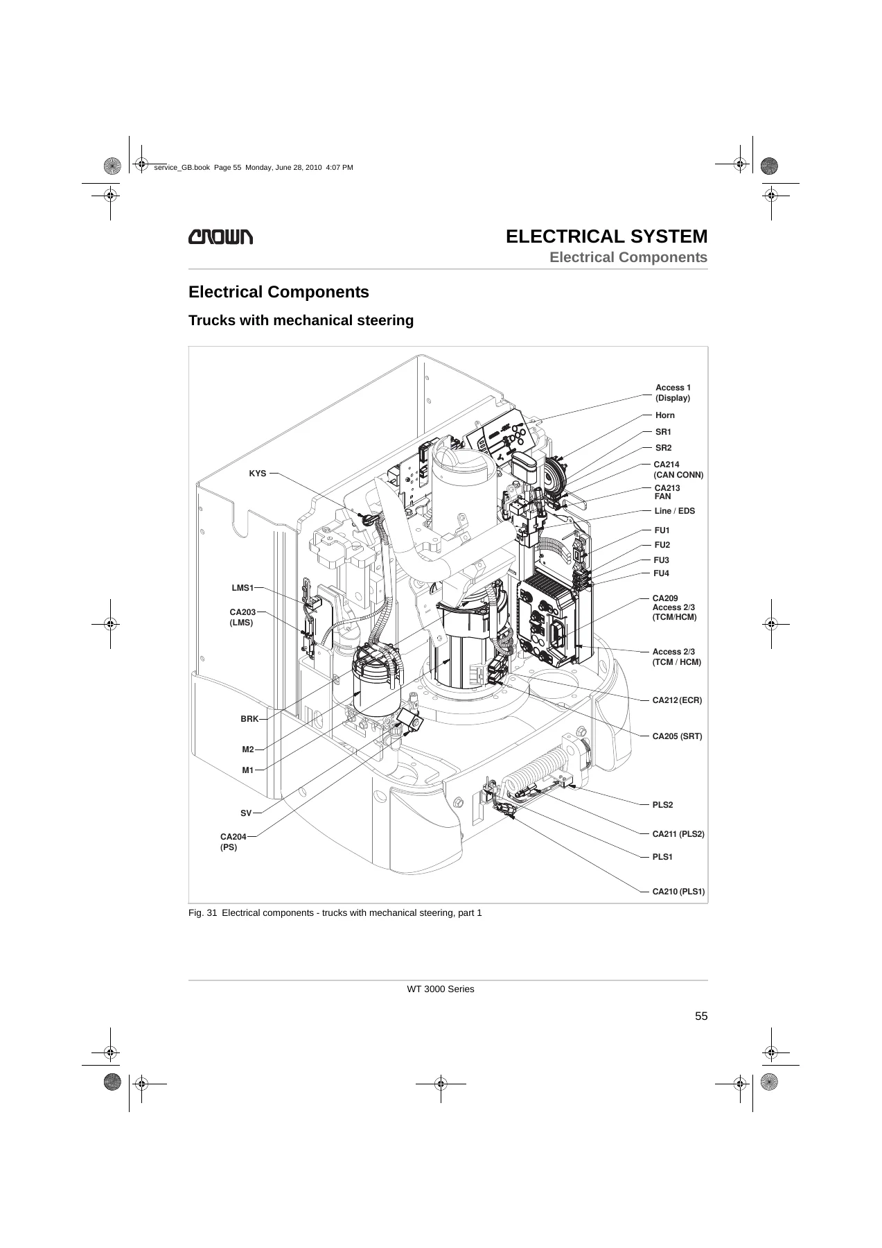
Electrical Componentsp. 71
Trucks with mechanical steeringp. 71
Trucks with electric steeringp. 73
Software Versionsp. 75
Menu Structurep. 77
Analyzer menu A1 – A2p. 79
Analyzer menu A3p. 80
Analyzer menu A3 – A4p. 81
Analyzer menu A1 & A2, Access 1 & Access 2 inputsp. 82
Analyzer Menu A2.3, Access 3 Inputsp. 83
Analyzer Menu A2.5, Access 5 Inputsp. 85
Calibration C1 – C2 (C2 – mechanical steering)p. 86
Calibration C3 – C4p. 87
Calibration C2 (C2 – electric steering)p. 88
Features F1p. 89
Features F2 – F4p. 91
Features F5p. 92
Features F6 – F7p. 93
Features F8 – F15p. 95
Hour menu H1 – H59p. 96
Events menu, E1 – E3p. 97
Performance P1 Menup. 98
Performance P2 Menup. 99
Performance P3 menup. 100
Performance P4-P9 menup. 101
Performance P10 – P18 Menup. 102
Utilities Menu U1p. 103
Event Codesp. 104
Malfunctions with event code displayp. 104
Locating malfunctionsp. 104
Digit convention for event codesp. 104
Event code 100 (WT 3020 -M, WT 3040 -M)p. 105
Event Code 100p. 105
Event code 202 (WT 3020 -M, WT 3040 -M)p. 107
Event Code 202p. 107
Event codes 203 – 204 (WT 3020 -M, WT 3040 -M)p. 109
Event Code 203p. 109
Event Code 204p. 109
Event code 205 (WT 3020 -M, WT 3040 -M)p. 111
Event Code 205p. 111
Event code 208 (WT 3020 -M, WT 3040 -M)p. 112
Event code 208p. 112
Event code 228 (WT 3020 -M, WT 3040 -M)p. 113
Event code 228p. 113
Event code 229 (WT 3020 -M, WT 3040 -M)p. 114
Event code 229p. 114
Event code 230 (WT 3020 -M, WT 3040 -M)p. 115
Event code 230p. 115
Event code 231 (WT 3020 -M, WT 3040 -M)p. 117
Event code 231p. 117
Event codes 232 – 233 (WT 3020 -M, WT 3040 -M)p. 118
Event code 232p. 118
Event code 233p. 118
Event code 234 (WT 3020 -M, WT 3040 -M)p. 119
Event code 234p. 119
Event code 300 (WT 3020 -M, WT 3040 -M)p. 120
Event code 300p. 120
Event codes 301 – 302 (WT 3020 -M, WT 3040 -M)p. 121
Event code 301p. 121
Event code 302 (WT 3020 -M, WT 3040 -M)p. 121
Event code 302p. 121
Event code 303 (WT 3020 -M, WT 3040 -M)p. 122
Event code 303p. 122
Event code 304 (WT 3020 -M, WT 3040 -M)p. 123
Event code 304p. 123
Event codes 305 – 306 (WT 3020 -M, WT 3040 -M)p. 125
Event code 305p. 125
Event code 306p. 125
Event code 307 (WT 3020 -M, WT 3040 -M)p. 126
Event code 307p. 126
Event code 308 (WT 3020 -M, WT 3040 -M)p. 127
Event code 308p. 127
Event codes 309 – 310 (WT 3020 -M, WT 3040 -M)p. 128
Event code 309p. 128
Event code 310p. 128
Event code 314 (WT 3020 -M, WT 3040 -M)p. 129
Event code 314p. 129
Event code 315 (WT 3020 -M, WT 3040 -M)p. 130
Event code 315p. 130
Event code 316 (WT 3020 -M, WT 3040 -M)p. 131
Event code 316p. 131
Event codes 317 – 319 (WT 3020 -M, WT 3040 -M)p. 132
Event code 317p. 132
Event code 319p. 132
Event code 320 (WT 3020 -M, WT 3040 -M)p. 133
Event code 320p. 133
Event code 321 (WT 3020 -M, WT 3040 -M)p. 134
Event code 321p. 134
Event codes 322 – 326 (WT 3020 -M, WT 3040 -M)p. 135
Event code 322p. 135
Event code 326p. 135
Event codes 328 – 329 (WT 3020 -M, WT 3040 -M)p. 136
Event code 328p. 136
Event code 329p. 136
Event codes 333 – 334 (WT 3020 -M, WT 3040 -M)p. 137
Event code 333p. 137
Event code 334p. 137
Event codes 337 – 338 (WT 3020 -M, WT 3040 -M)p. 138
Event code 337p. 138
Event code 338p. 138
Event code 341 (WT 3020 -M, WT 3040 -M)p. 139
Event code 341p. 139
Event code 342 (WT 3020 -M, WT 3040 -M)p. 140
Event code 342p. 140
Event code 343 (WT 3020 -M, WT 3040 -M)p. 141
Event code 343p. 141
Event codes 348 – 351 (WT 3020 -M, WT 3040 -M)p. 142
Event code 348p. 142
Event code 351p. 142
Event code 352 (WT 3020 -M, WT 3040 -M)p. 143
Event code 352p. 143
Event code 353 (WT 3020 -M, WT 3040 -M)p. 144
Event code 353p. 144
Event codes 354 – 355 (WT 3020 -M, WT 3040 -M)p. 145
Event code 354p. 145
Event code 355p. 145
Event code 356 (WT 3020 -M, WT 3040 -M)p. 146
Event code 356p. 146
Event code 357 (WT 3020 -M, WT 3040 -M)p. 147
Event code 357p. 147
Event codes 358 – 359 (WT 3020 -M, WT 3040 -M)p. 148
Event code 358p. 148
Event code 359p. 148
Event code 361 – 362 (WT 3020 -M, WT 3040 -M)p. 150
Event code 361p. 150
Event code 362p. 150
Event code 364 (WT 3020 -M, WT 3040 -M)p. 151
Event code 364p. 151
Event codes 365 – 368 (WT 3020 -M, WT 3040 -M)p. 153
Event code 365p. 153
Event code 368p. 153
Event codes 370 – 371 (WT 3020 -M, WT 3040 -M)p. 155
Event code 370p. 155
Event code 371p. 155
Events Displayed with Text Messages (WT 3020 -M, WT 3040 – M)p. 157
Platform Errorp. 157
Entry bar &/or FDSp. 158
Stoppedp. 159
Traction control module hotp. 161
Traction motor hotp. 162
Release control handlep. 163
Travel switch applied too soonp. 164
Event code 100 (WT 3040 -E, WT 3060 -E)p. 165
Event Code 100p. 165
Event code 200 – 201 (WT 3040 -E, WT 3060 -E)p. 166
Event code 200p. 166
Event code 201p. 166
Event code 202 (WT 3040 -E, WT 3060 -E)p. 167
Event Code 202p. 167
Event codes 203 – 204 (WT 3040 -E, WT 3060 -E)p. 169
Event Code 203p. 169
Event Code 204p. 169
Event code 205 (WT 3040 -E, WT 3060 -E)p. 170
Event Code 205p. 170
Event code 206 (WT 3040 -E, WT 3060 -E)p. 171
Event Code 206p. 171
Event code 207 (WT 3040 -E, WT 3060 -E)p. 172
Event Code 207p. 172
Event code 208 (WT 3040 -E, WT 3060 -E)p. 173
Event code 208p. 173
Event code 209 – 210 (WT 3040 -E, WT 3060 -E)p. 174
Event code 209p. 174
Event code 210p. 174
Event code 211 – 212 (WT 3040 -E, WT 3060 -E)p. 175
Event code 211p. 175
Event code 212p. 175
Event code 213 – 214 (WT 3040 -E, WT 3060 -E)p. 176
Event code 213p. 176
Event code 214p. 176
Event code 215 – 218 (WT 3040 -E, WT 3060 -E)p. 177
Event code 215p. 177
Event code 218p. 177
Event code 219 (WT 3040 -E, WT 3060 -E)p. 178
Event code 219p. 178
Event code 220 (WT 3040 -E, WT 3060 -E)p. 179
Event code 220p. 179
Event code 221 – 223 (WT 3040 -E, WT 3060 -E)p. 180
Event code 221p. 180
Event code 223p. 180
Event code 224 (WT 3040 -E, WT 3060 -E)p. 181
Event code 224p. 181
Event code 225 (WT 3040 -E, WT 3060 -E)p. 182
Event code 225p. 182
Event code 226 (WT 3040 -E, WT 3060 -E)p. 183
Event code 226p. 183
Event code 228 (WT 3040 -E, WT 3060 -E)p. 184
Event code 228p. 184
Event code 229 (WT 3040 -E, WT 3060 -E)p. 185
Event code 229p. 185
Event code 230 (WT 3040 -E, WT 3060 -E)p. 186
Event code 230p. 186
Event code 300 – 301 (WT 3040 -E, WT 3060 -E)p. 188
Event code 300p. 188
Event code 301p. 188
Event code 302 – 303 (WT 3040 -E, WT 3060 -E)p. 189
Event code 302p. 189
Event code 303p. 189
Event code 304 (WT 3040 -E, WT 3060 -E)p. 190
Event code 304p. 190
Event code 305 – 306 (WT 3040 -E, WT 3060 -E)p. 192
Event code 305p. 192
Event code 306p. 192
Event code 307 (WT 3040 -E, WT 3060 -E)p. 193
Event code 307p. 193
Event code 308 (WT 3040 -E, WT 3060 -E)p. 194
Event code 308p. 194
Event code 309 – 310 (WT 3040 -E, WT 3060 -E)p. 195
Event code 309p. 195
Event code 310p. 195
Event code 314 (WT 3040 -E, WT 3060 -E)p. 196
Event code 314p. 196
Event code 315 (WT 3040 -E, WT 3060 -E)p. 197
Event code 315p. 197
Event code 316 (WT 3040 -E, WT 3060 -E)p. 198
Event code 316p. 198
Event code 317 – 319 (WT 3040 -E, WT 3060 -E)p. 199
Event code 317p. 199
Event code 319p. 199
Event code 320 (WT 3040 -E, WT 3060 -E)p. 200
Event code 320p. 200
Event code 321 (WT 3040 -E, WT 3060 -E)p. 201
Event code 321p. 201
Event code 322 – 324 (WT 3040 -E, WT 3060 -E)p. 202
Event code 322p. 202
Event code 324p. 202
Event code 325 – 326 (WT 3040 -E, WT 3060 -E)p. 203
Event code 325p. 203
Event code 326p. 203
Event code 328 – 329 (WT 3040 -E, WT 3060 -E)p. 204
Event code 328p. 204
Event code 329p. 204
Event code 332 – 333 (WT 3040 -E, WT 3060 -E)p. 205
Event code 332p. 205
Event code 333p. 205
Event code 334 (WT 3040 -E, WT 3060 -E)p. 206
Event code 334p. 206
Event code 335 (WT 3040 -E, WT 3060 -E)p. 207
Event code 335p. 207
Event code 337 (WT 3040 -E, WT 3060 -E)p. 208
Event code 337p. 208
Event code 338 (WT 3040 -E, WT 3060 -E)p. 209
Event code 338p. 209
Event code 340 – 341 (WT 3040 -E, WT 3060 -E)p. 210
Event code 340p. 210
Event code 341p. 210
Event code 342 (WT 3040 -E, WT 3060 -E)p. 211
Event code 342p. 211
Event code 343 (WT 3040 -E, WT 3060 -E)p. 212
Event code 343p. 212
Event code 344 (WT 3040 -E, WT 3060 -E)p. 213
Event code 344p. 213
Event code 345 – 346 (WT 3040 -E, WT 3060 -E)p. 214
Event code 345p. 214
Event code 346p. 214
Event code 347 (WT 3040 -E, WT 3060 -E)p. 215
Event code 347p. 215
Event code 348 – 349 (WT 3040 -E, WT 3060 -E)p. 216
Event code 348p. 216
Event code 349p. 216
Event code 353 (WT 3040 -E, WT 3060 -E)p. 217
Event code 353p. 217
Event code 370 – 371 (WT 3040 -E, WT 3060 -E)p. 218
Event code 370p. 218
Event code 371p. 218
Events Displayed with Text Messages (WT 3040 -E, WT 3060 -E)p. 220
One hydraulic function at a timep. 220
Platform Errorp. 221
Entry bar &/or FDSp. 222
Stoppedp. 223
Traction control module hotp. 225
Traction motor hotp. 226
Release control handlep. 227
Travel switch applied too soonp. 228
Event code 500 – 501 (WT 3040 -E, WT 3060 -E)p. 229
Event Code 500p. 229
Event Code 501p. 229
Event codes 502 – 504 (WT 3040 -E, WT 3060 -E)p. 230
Event Code 502p. 230
Event Code 503p. 230
Event Code 504p. 230
Event codes 505 – 506 (WT 3040 -E, WT 3060 -E)p. 231
Event Code 505p. 231
Event Code 506p. 231
Event code 507 – 508 (WT 3040 -E, WT 3060 -E)p. 232
Event code 507p. 232
Event code 508p. 232
Event code 509p. 233
Event code 510 (WT 3040 -E, WT 3060 -E)p. 234
Event code 510p. 234
Event code 511 (WT 3040 -E, WT 3060 -E)p. 235
Event code 511p. 235
Event code 512 – 513 (WT 3040 -E, WT 3060 -E)p. 236
Event code 512p. 236
Event code 513p. 236
Event code 514 (WT 3040 -E, WT 3060 -E)p. 237
Event code 514p. 237
Event code 515 – 516 (WT 3040 -E, WT 3060 -E)p. 238
Event code 515p. 238
Event code 516p. 238
Event code 517 (WT 3040 -E, WT 3060 -E)p. 239
Event Code 517p. 239
Event code 518 – 519 (WT 3040 -E, WT 3060 -E)p. 240
Event code 518p. 240
Event code 519p. 240
Event code 520 – 522 (WT 3040 -E, WT 3060 -E)p. 241
Event code 520p. 241
Event code 522p. 241
Event code 523 (WT 3040 -E, WT 3060 -E)p. 242
Event code 523p. 242
Event code 524 – 525 (WT 3040 -E, WT 3060 -E)p. 243
Event code 524p. 243
Event code 525p. 243
Event code 526 (WT 3040 -E, WT 3060 -E)p. 244
Event code 526p. 244
Event code 527 (WT 3040 -E, WT 3060 -E)p. 245
Event code 527p. 245
Event code 528 – 529 (WT 3040 -E, WT 3060 -E)p. 246
Event code 528p. 246
Event code 529p. 246
Event code 530 (WT 3040 -E, WT 3060 -E)p. 247
Event code 530p. 247
Event code 531 (WT 3040 -E, WT 3060 -E)p. 248
Event code 531p. 248
Event code 532 (WT 3040 -E, WT 3060 -E)p. 249
Event code 532p. 249
Event code 533 (WT 3040 -E, WT 3060 -E)p. 250
Event code 533p. 250
Event code 535 – 536 (WT 3040 -E, WT 3060 -E)p. 251
Event code 535p. 251
Event code 536p. 251
Event code 537 (WT 3040 -E, WT 3060 -E)p. 252
Event code 537p. 252
Event code 538 (WT 3040 -E, WT 3060 -E)p. 253
Event code 538p. 253
Event code 539 – 540 (WT 3040 -E, WT 3060 -E)p. 254
Event code 539p. 254
Event code 540p. 254
Event code 541 – 542 (WT 3040 -E, WT 3060 -E)p. 255
Event code 541p. 255
Event code 542p. 255
Event code 543 (WT 3040 -E, WT 3060 -E)p. 256
Event code 543p. 256
Event code 544 (WT 3040 -E, WT 3060 -E)p. 257
Event code 544p. 257
Event code 545 – 547 (WT 3040 -E, WT 3060 -E)p. 258
Event code 545p. 258
Event code 547p. 258
Events Displayed with Text Messages (WT 3040 -E, WT 3060 -E)p. 259
Steering controller hotp. 259
Steer motor hotp. 260
Input Signalsp. 263
Initial truck statusp. 263
SAS and BRSp. 263
Folding platform trucksp. 263
Fixed platform trucksp. 265
Platform and Side Restraint Logicp. 267
Conventionsp. 267
Brief description of equipmentp. 267
Folding platformp. 267
Side restraint and platform setting definitionp. 267
Fixed platformp. 268
Analyzer Menup. 269
Selecting the ANALYZER Menup. 269
Testing the fansp. 270
Selecting the ANALYZER Menup. 270
Calibrationp. 271
Selecting the CALIBRATION Menup. 271
Calibrating the traction potentiometerp. 271
Travel direction definitionp. 271
Electric steering calibrationp. 272
Calibrating the SRT option for mechanical steeringp. 274
Calibrating the load sensorp. 275
Software Parameter Settingsp. 277
Conventionsp. 277
Brief description of equipmentp. 277
Markingsp. 277
Parameters that can be set separately in performance settings P1 – P3p. 277
Trucks with electric steering and fixed platform in rider modep. 277
Trucks with mechanical steering and fixed platform in rider modep. 278
Folding platform trucks in pedestrian modep. 278
Folding platform trucks in rider mode (except WT3020 MO)p. 279
Folding platform trucks in pedestrian modep. 279
Parameters with the same setting for all performance profilesp. 280
All trucksp. 280
Trucks with electric steeringp. 281
Trucks with mechanical steeringp. 281
All trucks in rider modep. 282
All trucks in pedestrian modep. 282
All trucks with fixed platformp. 282
Servicing and Replacing the Control Modulesp. 283
Generalp. 283
Power fusesp. 283
Discharging the capacitorsp. 283
Servicing the control modulesp. 283
Replacing control modulesp. 283
Removing the control modulep. 283
Assembling the control modulep. 284
Control Module PMT Testp. 285
Generalp. 285
Required toolsp. 285
PMT Testp. 285
Testing Access 2p. 285
Testing Access 3p. 286
Testing Access 5p. 287
General DC Motor Maintenance Instructionsp. 288
Brushesp. 288
Motorp. 288
Armaturep. 288
Traction Motor (M1)p. 289
Traction motor disassemblyp. 289
Traction motor assemblyp. 289
Repairing the traction motorp. 290
Preparationp. 290
Dismantling the rotor assemblyp. 290
Assembling the rotor assemblyp. 290
Final tasksp. 290
Pump Motor (M2)p. 291
1.2 kW pump motorp. 291
Brushesp. 291
Armaturep. 291
2.2 kW pump motorp. 291
Brushesp. 291
Armaturep. 291
Steer Motor (M3)p. 292
Special tools requiredp. 293
Steer motor disassemblyp. 293
Steer motor assemblyp. 293
Repairing the steer motorp. 293
Preparationp. 293
Steer motor disassemblyp. 293
Steer motor assemblyp. 293
Final tasksp. 293
Battery Informationp. 294
Charging the batteryp. 294
Replacing the batteryp. 294
Battery Discharge Indicator (BDI)p. 295
Load profile and discharge curvep. 295
Adapting the BDI settingp. 295
Repairing Contactorsp. 297
Wear testp. 297
Checking the contactsp. 297
Checking the coilsp. 297
Checking the springsp. 297
Modificationsp. 298
Modifying β€œpower up with Enter key” to β€œpower up with key switch”p. 298
Modifying β€œpower up with key switch” to β€œpower up with Enter”p. 298
Brake Systemp. 301
Components and Operationp. 303
Service brakep. 303
Parking brakep. 303
Servicing the parking brakep. 304
Measuring the air gapp. 304
Troubleshootingp. 304
Replacing the Parking Brakep. 305
Parking brake disassemblyp. 305
Parking brake assemblyp. 305
Testing the Braking Distancep. 307
Requirementsp. 307
Performing the testp. 307
Braking distance tablesp. 307
WT 3020 maximum braking distancesp. 307
WT 3040 mechanical steering, maximum braking distancesp. 307
WT 3040 electric steering, maximum braking distancesp. 308
WT 3060 maximum braking distancesp. 308
Steeringp. 309
Replacing the SAHS Sensorp. 311
SAHS removalp. 311
SAHS adjustmentp. 311
SAHS assemblyp. 311
Repairing Control Handle Return Springsp. 312
Removing the coversp. 312
Return spring pre-tension adjustmentp. 312
Replacing the return springsp. 313
Return spring removalp. 313
Return spring assemblyp. 313
Tools required:p. 313
Repairing the Control Handlep. 314
Replacing the control handle shellsp. 315
Shell removalp. 315
Shell assemblyp. 316
Replacing the switch unitp. 316
Switch unit removalp. 317
Switch unit assemblyp. 317
Replacing the β€œrabbit/turtle” toggle modulep. 317
Toggle module removalp. 317
Toggle module assemblyp. 318
Replacing the control handle grip PC boardsp. 318
Hydraulic PC board removalp. 318
Hydraulic PC board assemblyp. 318
Main PC board removalp. 318
Main PC board assemblyp. 318
Replacing the traction potentiometerp. 319
Traction potentiometer removalp. 319
Traction potentiometer assemblyp. 320
Replacing the safety reverse switch (SAS)p. 320
Removing the safety reverse switch (SAS)p. 320
SAS / BRS switch assemblyp. 321
Replacing the grips and horn switchp. 321
Lifting Mechanismp. 323
Checking and Adjusting the Fork Height (Lowered)p. 325
Requirementsp. 325
Checking the stopp. 325
Adjusting the stopp. 325
Adjusting the Lift Limit Cutout and Fork Height (Raised)p. 328
Adjusting the lift limit cutoutp. 328
Checking the fork lift heightp. 329
Forksp. 330
Generalp. 330
Fork inspectionp. 330
Checking forks for cracksp. 330
Cylindersp. 331
Generalp. 333
Safety instructionsp. 333
Hydraulic system repair instructionsp. 333
Cylinder repair instructionsp. 333
Toolsp. 334
Small hookp. 334
Extractorp. 334
Producing extractorsp. 334
Groove aligning arbor for small rod sealsp. 334
Assembly devices for large rod sealsp. 335
Protective mechanismsp. 335
Rod Seal Removal and Assemblyp. 336
Removing a large rod sealp. 336
Removing a small rod sealp. 336
Inserting a large rod sealp. 336
Fitting a small rod sealp. 337
Rod seal assembly, sealing lip firstp. 337
Cylinders and Cylinder Operationp. 338
Hydraulic system with lift cylindersp. 338
Hydraulic system with lift cylinders and traction cylinderp. 338
Replacing the Lift Cylindersp. 339
Lift cylinder removalp. 339
Lift cylinder assemblyp. 340
Repairing Lift Cylindersp. 341
Replacing the Traction Cylinderp. 343
Removing the traction cylinderp. 343
Traction cylinder assemblyp. 344
Repairing the Traction Cylinderp. 345
Platformp. 347
Adjusting the Folding Platform Switchp. 349
Pre-tensioning the spring assemblyp. 349
Checking and adjusting switch PLS1 for rider modep. 349
Adjusting switch PLS2 for pedestrian modep. 350
Replacing the Folding Platform Springsp. 351
Spring removalp. 351
Spring assemblyp. 351
Schematic Diagramsp. 353
Wire Colour Codep. 355
General contact symbol abbreviationsp. 356
Electrical wiring diagramsp. 358
Designation List (Mechanical Steering)p. 360
Connectors, standardp. 360
Connectors, optionsp. 362
Rear entryp. 362
Side entryp. 362
InfoLink V2.5p. 362
Beaconsp. 363
Transformersp. 363
Jumpersp. 363
Electrical Diagram, Keyless Start Upp. 367
Electrical Diagram, with Keypadp. 369
Access 3/2 Power Sidep. 371
Access 3/2 Logic Sidep. 372
Sensorsp. 373
Platform Switchp. 374
Adaptors CA200, CA201, CA205, CA206p. 375
PCBs in the Control Handlep. 376
Power Up Circuitryp. 377
Electrical Diagram, Keyless Start Upp. 379
Electrical Diagram with Keypad and/or Key Switchp. 380
Access 3/2 Power Sidep. 381
Access 3/2 Logic Sidep. 382
Sensorsp. 383
Platform Switchp. 384
Adaptors CA200, CA201, CA205, CA206p. 385
PCBs in the Control Handlep. 386
Power Up Circuitryp. 387
Infolink Connectionsp. 388
Designation List (Electric Steering)p. 389
Connectors, standardp. 389
Connectors, optionsp. 392
Fixed platform with side entryp. 392
InfoLink V2.5p. 392
Key switch, keyless start up, jumperp. 392
Beaconsp. 392
Alarmp. 392
Transformerp. 393
Jumpersp. 393
Electrical Diagram, Keyless Start Upp. 397
Electrical Diagram with Keypad and/or Key Switchp. 398
Access 3/2 Power Sidep. 399
Access 3/2 Logic Sidep. 400
Access 5 Logic Sidep. 401
Access 8p. 402
Switches and Sensors 1p. 403
Switches and Sensors 2p. 404
PCBs in the Control Handlep. 405
Power Up Circuitryp. 406
CAN Bus connectionsp. 407
Electrical Diagram, Keyless Start Upp. 409
Electrical Diagram with Keypad and/or Key Switchp. 410
Access 3/2 & Access 5 Power Sidep. 411
Access 3/2 Logic Sidep. 412
Access 5 Logic Sidep. 413
Access 8p. 414
Switches and Sensors 1p. 415
Switches and Sensors 2p. 416
PCBs in the Control Handlep. 417
Power Up Circuitryp. 418
CAN Bus and InfoLink connectionsp. 419
Main Harnessp. 420
Control Handle Wire Harnessp. 423
Jumper, Side Restraintp. 424
Power Cablep. 425
Main Wire Harnessp. 426
Control Handle CANp. 429
Sensor SAHS with Cablep. 430
TFD Modulep. 431
Jumpers JC208 and JC209p. 432
Control Handle CAN BusCablep. 433
Wire Harness for Control Handlep. 434
Key Switch, Jumper (PC225.1 & PC225.2)p. 436
Power Cablep. 437
Horn Switch Cablep. 438
Horn Switch with Cablep. 439
Wire Harness for Control Handlep. 440
Key Switch Adapterp. 441
Travel Alarm Connecting Cablep. 442
Transformer Connecting Cablep. 443
Beacon Connecting Cablep. 444
Beacon Power Supply Connecting Cablep. 445
Entry Bar Wire Harness (3040 -R -S and 3060 -R -S only)p. 446
Strobe Connecting Cablep. 447
InfoLink, Removable Batteryp. 448
InfoLink, Removable Batteryp. 450
InfoLink, Battery Rollersp. 452
InfoLink V2.5, Battery Rollersp. 454
Brake Switch Assemblyp. 455
Filter, Strobe Lightp. 456
Hydraulic Schematicp. 457
Hydraulic Symbolsp. 459
Hydraulic Diagram, Trucks without Traction Controlp. 463
Hydraulic Diagram, Trucks with Traction Controlp. 464


IMAGES PREVIEW

Crown WT 3000 Series Pallet Truck Maintenance Manual - WT 3020, WT 3040, WT 3060 β€” PDF page 1 preview
Crown WT 3000 Series Pallet Truck Maintenance Manual - WT 3020, WT 3040, WT 3060 β€” PDF page 3 preview
Crown WT 3000 Series Pallet Truck Maintenance Manual - WT 3020, WT 3040, WT 3060 β€” PDF page 71 preview

Reviews

There are no reviews yet.

Be the first to review “Crown WT 3000 Series Pallet Truck Maintenance Manual – WT 3020, WT 3040, WT 3060”

What Our Customers Say

β˜…β˜…β˜…β˜…β˜… Live reviews from customers
Loading customer reviews...
0
    0
    Your Cart
    Your cart is emptyReturn to Shop
    πŸ›’
    Recently Purchased
    πŸ•’ verified order