★ TRUSTED BY 321,897+ PROFESSIONALS WORLDWIDE
🏒
Trusted Business
Verified & Licensed
πŸ›‘οΈ
Virus Free Files
100% Safe Downloads
πŸ”’
Secure Payment
SSL Protected
⚑
Instant Delivery
Available Immediately
Sale!

BT Prime-Mover OE35 Order Selector Service Manual – 24V and 36V Order Picker Repair Guide

Original price was: $34.95.Current price is: $21.95.

Complete BT Prime-Mover OE35 Order Selector service manual, doc 301460-003. Covers 24V and 36V trucks: drive motor, transmission, brakes, EV100 LX SCR control, hydraulics, 2- and 3-stage masts, and Micro 70 wire guidance. 332-page PDF workshop guide.

⚑
Instant PDF Download
Available immediately
πŸ’Ύ
Save to Your Device
Download & keep forever
πŸ›‘οΈ
Antivirus Scanned
100% virus-free
🌍
Trusted Worldwide
175,000+ customers

Description

BT Prime-Mover OE35 Order Selector Service Manual

This is the complete BT Prime-Mover OE35 Order Selector Service Manual, document number 301460-003, for the 24-volt and optional 36-volt battery-powered counterbalanced order selector trucks. It is the workshop-level document written for technicians who actually work on the machine, and it follows the OE35 the whole way through: drive motor, double-reduction transmission, brake and wheel system, EV100 LX SCR traction control, duplex steering and brake-release pump, hydraulic lift circuit, two- and three-stage masts, and the Micro 70 wire guidance system.

When an OE35 will not travel, will not lift, throws a status code, or drifts off the guidewire, the answer is almost always a number in this book – a brush minimum, a relief setting, a torque value, a shim clearance, a status-code meaning. This is where those numbers live.

File Details

  • Manual type: Service Manual (workshop / repair)
  • Brand: BT Prime-Mover
  • Model covered: OE35 Order Selector
  • Document number: 301460-003
  • Electrical systems covered: 24 V and optional 36 V
  • Language: English
  • Page count: 332 pages
  • File format: PDF
  • Publisher: BT Prime-Mover, Inc., Muscatine, Iowa
  • Publication dates referenced: 1996-1997

Chapters Covered

  • BT Standard Codes, Warning Levels, Prohibitory and Ordinance Symbols
  • Introduction and How the Service Manual Is Organised
  • Machine Information – OE35 Presentation, Intended and Forbidden Applications, Truck Data, Dimensions, Data Plate, U.L. Construction Type
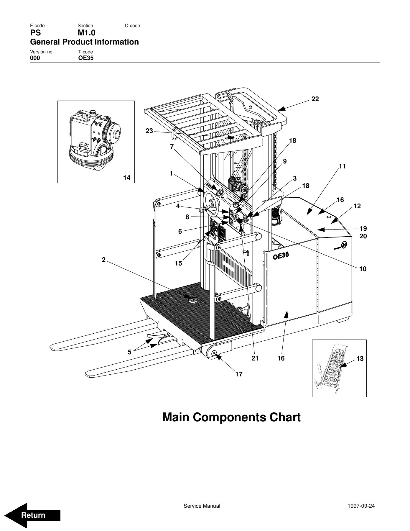
  • Main Components – Steering Wheel, Parking Brake Pedal, Key Switch, Emergency Stop, Pallet Clamp, Start Switch, Steering Direction Indicator, Fork Raise and Lower Switches, Horn, Hydraulic Pump Unit, Solenoid Valve, Battery, Drive Unit with Brake
  • Inch (SAE) and Metric Fasteners – Nomenclature, Threads, Strength Identification, Grade and Property Class Markings, Torque Nut Designations, Fastener Torque Values
  • Conversion of Metric and English Units
  • Technical Service Data
  • Ordering Spare Parts
  • Planned Maintenance Schedule
  • Planned Maintenance Procedures – Daily / Each 8-Hour Shift, Monthly / 250 Hours, Annual / 1200 Hours
  • Lubrication Chart and Approved Oils and Grease
  • Inspection Covers and Removal of the Plastic Dash Panel
  • Drive Motor 24 Volt – Component Repair, Inspection and Troubleshooting, Changing Brushes, Armature and Field Testing
  • Drive Motor 36 Volt – Component Repair, Inspection and Troubleshooting, Changing Brushes
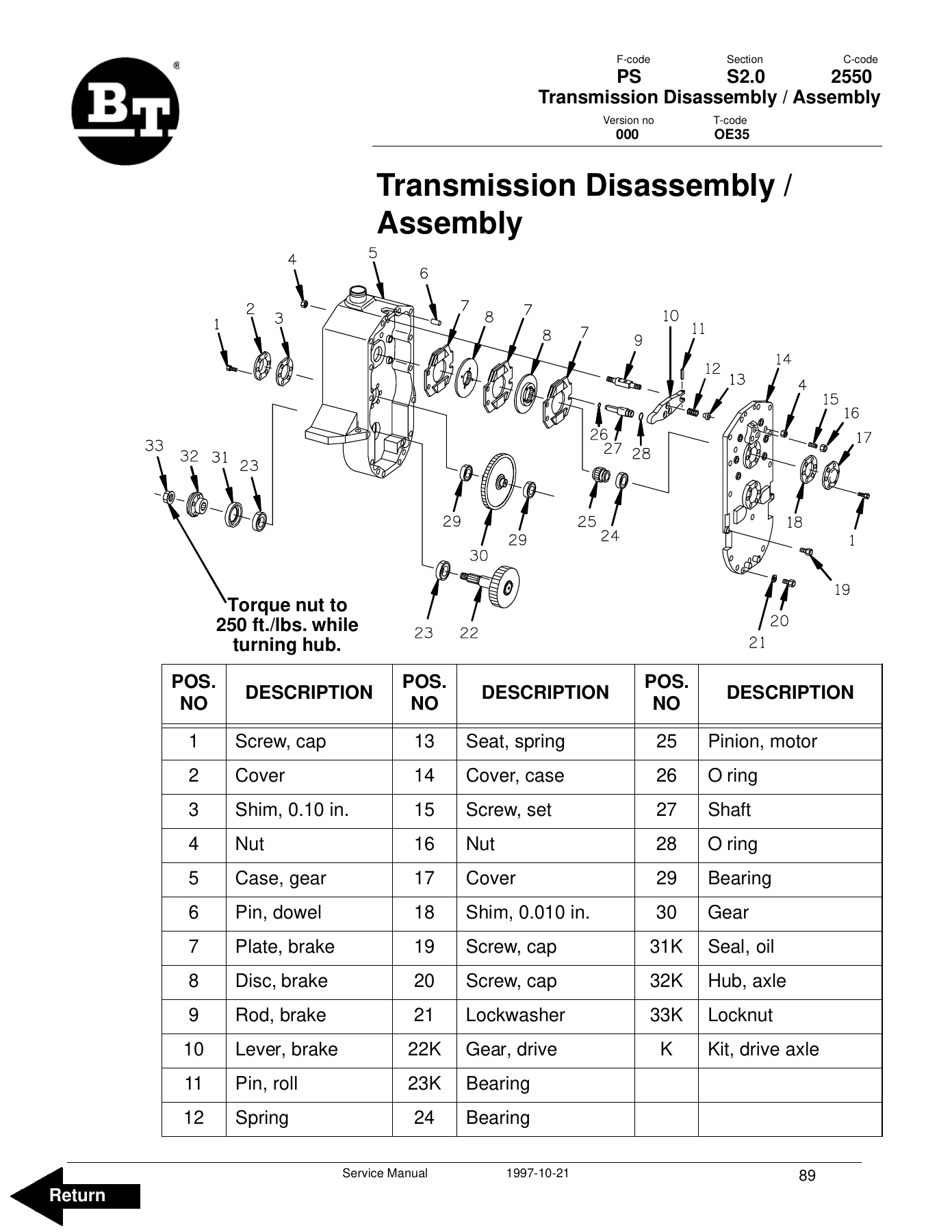
  • Transmission – System Description, Troubleshooting, Removal, Disassembly and Assembly, Installation
  • Drive Wheel, Load Wheels, Stabilizing Caster (Spring Loaded) – Removal, Inspection, Disassembly, Installation
  • Torque Generator – Disassembly and Assembly
  • Steering System Pump – General Information, Removal, Installation, Disassembly, Inspection, Assembly
  • Electrical System with TX and TT Card – Electrical Schematic Parts 1 and 2, Basics of Circuit Operation, Control Features
  • Battery Controller / Hourmeter / Lift Interrupt – General Information, Electrical, Battery Controller (BC), Troubleshooting
  • Dash Display – General Information, Location, Operational Checks, Status Codes
  • EV100 LX Control Status Codes (including Codes -01 through -57)
  • SCR Component Checks – Main Logic Card, Capacitor 1C, Forward and Rearward Contactors, 1A Contactor, Power Steering and Pump Contactors, Accelerator Potentiometer, SCRs (1REC, 2REC, 5REC), Rectifiers (3REC, 4REC, Diode Blocks), Thermal Protector, Filter Blocks, 1X Choke and Reactor T3-T4
  • Replacement of EV100 Components and EV100 Plug Instructions
  • Direction Contactor – General Information, Remove and Replace Contact Tips
  • 1A Speed Contactor – General Information, Disassembly, Assembly
  • Electrical System Troubleshooting – Control Circuits and Power Circuits
  • Electrical System Troubleshooting Charts – Emergency Disconnect Contactor, Steering and Brake Release Pump, Travel, Lift, Lowering
  • Pump Contactor and Steering Pump Contactor – General Information, Disassembly, Assembly
  • EV100 Handset Operation – Purpose, Operation, Function Set-Up Procedures, Function Numbers for Controllers
  • Hydraulic System – Hydraulic Schematic, General Information, Lift and Lower, Power Steering, Brake Release, Maintenance, Adjustments, Hydraulic Troubleshooting Chart
  • Lift Pump Assembly – Removal, Disassembly, Inspection, Assembly
  • Mast, 2 Stage – Shimming the Platform, Shimming the Rails, Removal, Installation, Disassembly, Assembly
  • Mast, 3 Stage – Shimming the Platform, Shimming the Rails, Removal, Installation, Disassembly, Assembly
  • Lift Cylinder, 2 Stage – Cylinder Repair
  • Freelift Cylinder, 3 Stage – Cylinder Repair
  • Staging Cylinder, 3 Stage – Removal, Disassembly, Assembly, Installation
  • Micro 70 Wire Guidance – Powering Up and Down, Electrical Schematics Parts 1-4, Cautions and Warnings, Operation Information, Component Function and Relationship, Truck Set Up On Site, Troubleshooting Information and Charts

Taken as a whole, this is a full-system service reference rather than a single-subject repair note. The first third establishes the machine and the standards you work to – truck data, fastener grades and torque values, unit conversions, the planned maintenance intervals at 8, 250 and 1200 hours, and the lubrication and oil specification charts. The service section then takes each assembly apart in order: electric drive motor, transmission and brake, wheels and caster, torque generator and steering pump, and the complete EV100 LX electrical package with its status-code diagnostics. The hydraulics section covers the lift circuit and lift pump down to seal and wear-plate inspection, and the mast section covers shimming, chain tensioning and column disassembly for both two-stage and three-stage masts. The final section handles the Micro 70 wire guidance system end to end, including the on-site set-up and alignment procedure and the fault charts used to trace antenna, tachometer, FTI 7 and FSA servo problems.

Diagnostics Built Into the Manual

Two areas make this document unusually practical. The first is the EV100 LX status code set. Every code is presented with its description, memory recall flag, circuit affected, symptom, possible cause and the actual voltage or resistance test to run – so a code -44 or -49 is not just a number, it is a defined test sequence on 1REC, 2REC, 5REC and the snubber circuits. The second is the Micro 70 guidance troubleshooting, which walks through antenna voltage swings, FTI 7 zero and feedback potentiometer calibration, FSA output checks and the frequency-matching jumpers on the Micro 70 controller.

The electrical troubleshooting charts follow the same pattern: start at the battery, work through fuses, key switch, emergency disconnect contactor, foot pedal, gate switches and directional switches, testing battery voltage at each point, with the repair listed directly under each failed test.

Specifications You Will Actually Use

The technical service data and hydraulic setting tables give the working numbers for both voltage variants – drive motor minimum brush length, minimum commutator diameter, brush spring tension, transmission gear ratio and oil type, drive and load wheel sizes, lifting pressure at rated load, steering and brake relief valve settings, hydraulic tank volume, fuse ratings and battery capacity and weight ranges. The planned maintenance schedule cross-references each task to an interval in hours and in days, weeks or months, so you can build a service programme around real operating shifts rather than a guess.

Who This Manual Suits

It is written for authorised technicians servicing the OE35, and it assumes a workshop environment – jacking and blocking procedures, solvent handling warnings, compressed air limits and personal protective equipment are stated up front in every disassembly section. That said, a competent maintenance engineer or a fleet operator running an OE35 in a warehouse will find the diagnostic charts and the adjustment values usable on their own, particularly the hydraulic relief adjustment, brake aggressiveness setting and mast shim clearance limits.

Complete PDF Bookmark Tree

Complete Bookmarks

The complete bookmarks in the β€œBT Prime-Mover OE35 Order Selector Service Manual – 24V and 36V Order Picker Repair Guide” are as follows:

Front Coverp. 1
BT Standard Codesp. 3
Warning Symbolsp. 11
1. Warning Levelsp. 11
Prohibitory Symbolsp. 12
1. Ordinance Symbolsp. 12
Introduction, Service Manualp. 13
Contents, Section Mp. 15
1. Machine Informationp. 15
General Product Informationp. 17
1. Presentation of the OE35p. 17
1.1. Intended Application of the Trucksp. 17
1.2. Forbidden Application of the Truckp. 18
1.3. Truck Datap. 18
1.4. OE35 Dimensionsp. 19
1.5. Data Platep. 20
1.6. U.L. Construction Typep. 21
2. Main Componentsp. 22
Inch (SAE) and Metric Fastenersp. 25
1. Introductionp. 25
2. Nomenclature, Threadsp. 26
3. Strength Identificationp. 27
4. Conversion of Metric and English Unitsp. 33
Technical Service Datap. 35
Ordering Spare Partsp. 39
Introduction, Maintenancep. 41
1. Safe Jacking Procedurep. 41
Service Schedulep. 43
1. Planned Maintenance Schedulep. 43
Planned Maintenance Proceduresp. 47
1. Services to be performed daily or at each 8 hour operating shiftp. 47
1.1. Battery Discharge Indicator with slow downp. 47
1.2. Dash Displayp. 47
1.3. Hydraulic Systemp. 48
1.4. Frame/Sheet Metalp. 48
1.5. Wheels/Tiresp. 48
1.6. Functions/Operationsp. 48
2. Services to be performed monthly or every 250 operating hoursp. 49
2.1. Inspectionp. 49
2.2. Transmissionp. 49
2.3. Brakesp. 49
2.4. Batteryp. 49
2.5. Electrical Connectionsp. 50
2.6. Contactor Tips (NOT Sealed)p. 50
2.7. Motor Brushesp. 50
2.8. Drive Motorp. 50
2.9. Hydraulic Reservoirp. 51
2.10. Frame Lubep. 51
2.11. Pivot Pointsp. 51
3. Services to be performed annually or every 1200 operating hoursp. 52
3.1. Inspectionp. 52
3.2. Transmissionp. 52
3.3. Batteryp. 52
3.4. Hydraulic Systemp. 53
3.5. Brakesp. 53
Lubrication Chartp. 55
Oil and Grease Specificationsp. 57
1. Approved Oils and Greasep. 57
Contents, Section Sp. 59
1. Service Instructionsp. 59
Inspection Coversp. 61
1. Removal Of Plastic Dash Panelp. 62
Drive Motorp. 65
1. General Informationp. 65
2. Operating Conditionsp. 65
3. Troubleshootingp. 65
Drive Motor 24 Voltp. 71
1. Component Repairp. 72
2. Inspection and Troubleshootingp. 73
2.1. Drive End Headp. 73
2.2. Commutator End Headp. 73
2.3. Bearingsp. 73
2.4. Brush and Commutatorp. 74
2.5. Armaturep. 74
2.6. Frame and Field Assemblyp. 75
2.6.1. Testingp. 75
2.6.2. Frame and Field Service Notesp. 76
2.7. Assemblyp. 77
2.7.1. Field Coil Installationp. 77
2.7.2. Bearing Installationp. 77
2.7.3. After Assemblyp. 78
3. When changing brushesp. 78
Drive Motor 36 Voltp. 79
1. Component Repairp. 80
1.1. Disassemblyp. 80
2. Inspection and Troubleshootingp. 81
2.1. Drive End Headp. 81
2.2. Commutator End Headp. 81
2.3. Bearingsp. 81
2.4. Brush and Commutatorp. 82
2.5. Armaturep. 82
2.6. Frame and Field Assemblyp. 83
2.6.1. Testingp. 83
2.6.2. Frame and Field Service Notesp. 84
2.7. Assemblyp. 85
2.7.1. Field Coil Installationp. 85
2.7.2. Bearing Installationp. 85
2.7.3. After Assemblyp. 86
3. When Changing Brushesp. 86
Transmissionp. 87
1. System descriptionp. 87
2. Troubleshootingp. 87
3. Removalp. 88
Transmission Disassembly / Assemblyp. 91
4. Disassemblyp. 92
5. Installationp. 99
Drive Wheelp. 101
5.1. Removalp. 101
5.2. Installationp. 102
Load Wheelsp. 103
Stabilizing Caster Spring Loadedp. 105
1. Removalp. 106
2. Inspectionp. 108
3. Disassemblyp. 109
3.1. Installationp. 109
Torque Generatorp. 111
1. Disassemblyp. 113
2. Assemblyp. 118
Steering System Pumpp. 125
1. General Informationp. 126
2. Removalp. 126
3. Installationp. 127
4. Disassemblyp. 129
5. Inspectionp. 130
6. Assemblyp. 130
Steering Systemp. 133
1. General Informationp. 133
Electrical System with TX and TT Cardp. 135
1. Electrical Schematic Part 1p. 135
2. Electrical Schematic Part 2p. 136
3. Basics Of Circuit Operationp. 137
4. Control Featuresp. 139
4.1. Oscillatorp. 139
4.2. Current Limitp. 140
4.3. Pluggingp. 140
4.4. Pedal Position Plugp. 140
4.5. Ramp Startp. 141
4.6. Full Power Transitionp. 141
4.7. Control Acceleration and 1A Timep. 141
4.8. 1A Current Drop Outp. 141
4.9. Static Return to OFFp. 142
4.10. Accelerator Volts Hold-OFFp. 142
4.11. Coil Driver Modulesp. 142
4.12. 1A Thermal Hold-OFFp. 142
4.13. Must Pulse to Timep. 142
4.14. Pulse Monitor Trip (PMT)p. 143
4.15. Thermal Protector – (TP)p. 144
4.16. Low Voltagep. 144
4.17. Top Speed (Motor volts) Limitp. 144
4.18. Steer Pump Contactor Time Delayp. 144
4.19. Constant Current Coil Drivers and Internal Coil Suppressionp. 145
4.20. Hourmeter Readingsp. 145
4.21. Internal Resistance Compensationp. 145
4.22. Stored Status Codep. 145
4.23. On-board Diagnosticsp. 145
4.24. Battery Discharge Indicationp. 146
4.25. Handsetp. 146
5. General Maintenance Instructionsp. 147
6. Trouble-shooting Instructionsp. 148
Battery Controller / Hourmeter / Lift Interruptp. 151
1. General Informationp. 151
2. Electricalp. 151
2.1. Voltagep. 151
2.1.1. The Contact Voltage and Current Ratings for Switching Resistive Loads.p. 152
2.1.2. Memory Retentionp. 152
3. Battery Controller (BC)p. 152
3.1. General Informationp. 152
3.1.1. Discharge Adjustmentp. 152
3.2. Resetp. 154
3.3. Key Switchp. 154
3.4. Hourmeterp. 155
4. Troubleshootingp. 155
4.1. Battery Discharge Indicator (BDI)p. 155
4.1.1. No Resetp. 155
4.1.2. Reset After Break in Powerp. 155
4.1.3. No Discharge, Gauge Does Not Run Downp. 156
4.1.4. No Lockoutp. 156
4.1.5. No Liftp. 156
4.1.6. Early Lockoutp. 157
4.1.7. LEDs Do Not Lightp. 157
4.2. Hourmeterp. 157
4.2.1. No Displayp. 157
4.2.2. Hourmeter Glass Icon Does Not Flashp. 157
4.2.3. Hourmeter Glass Icon Always Flashesp. 158
Dash Displayp. 159
1. General Informationp. 159
2. Locationp. 160
3. Operational Checksp. 160
3.1. Checking Hourmeterp. 160
3.2. Checking Battery Condition (BDI).p. 160
3.3. Checking Status Code (wrench).p. 160
4. Status Codesp. 161
EV100 LX Control Status Codesp. 163
SCR Component Checksp. 181
1. Main Logic Cardp. 181
1.1. Instructions for Removal of Control Card.p. 181
2. Capacitor 1Cp. 182
3. Contactors Forward, Rearward, 1A, Power Steering, and Pumpp. 182
4. Potentiometer in Acceleratorp. 182
5. SCR’s (1REC, 2REC, 5REC)p. 182
6. Rectifiers (3REC, 4REC, Diode Blocks)p. 184
7. Thermal Protector (TP)p. 184
8. Filter Block (23FIL, etc.)p. 185
9. Filter Block (23FIL, etc.)p. 185
10. 1X Choke and Reactor T3-T4p. 185
11. Replacement of EV100 Componentsp. 185
11.1. 1REC, 2REC or 5RECp. 186
11.2. Capacitorp. 186
11.3. 22REC, 23REC and 25RECp. 187
12. Instructions – EV100 Plugsp. 187
12.1. Generalp. 187
12.2. Proceduresp. 187
12.3. Referencep. 188
Direction Contactorp. 189
1. General Informationp. 190
2. Remove / replace contact tipsp. 190
1A Speed Contactorp. 195
1. General Informationp. 196
2. Disassemblyp. 196
3. Assemblyp. 198
Electrical System Troubleshootingp. 201
1. Control Circuits and Power Circuitsp. 203
Electrical System Troubleshooting Chartsp. 205
Pump Contactorp. 217
1. General Informationp. 218
2. Disassemblyp. 218
3. Assemblyp. 220
Steering Pump Contactorp. 223
1. General Informationp. 224
2. Disassemblyp. 224
3. Assemblyp. 226
EV100 Handset Operationp. 229
1. General Informationp. 229
2. Purposep. 230
3. Operationp. 231
4. Function Set-Up Proceduresp. 232
5. Description and Locationp. 234
6. Function Numbers for Controllersp. 235
6.1. Function 1p. 235
6.2. Function 2p. 235
6.3. Function 3p. 235
6.4. Function 4p. 236
6.5. Function 5p. 236
6.6. Function 6p. 236
6.7. Function 11p. 237
6.8. Function 12p. 237
6.9. Function 13p. 237
6.10. Function 14p. 238
6.11. Function 15p. 239
6.12. Function 16p. 239
6.13. Function 17p. 240
6.14. Function 18p. 241
Hydraulic Systemp. 243
1. Hydraulic Schematicp. 243
2. General Informationp. 244
2.1. Lift/lowerp. 244
2.2. Power Steeringp. 245
2.3. Brake Releasep. 245
3. Maintenancep. 246
4. Adjustmentsp. 246
Hydraulic Troubleshootingp. 247
1. Troubleshooting Chartp. 247
Lift Pump Assemblyp. 251
1. Removalp. 252
2. Disassemblyp. 253
3. Inspectionp. 256
4. Assemblyp. 258
Mast, 2 Stagep. 261
1. Shimming Mast on Truck.p. 262
1.1. Shimming the Platform.p. 262
1.2. Shimming the Railsp. 263
2. Two Stage Mastp. 266
2.1. Removalp. 266
2.2. Installationp. 267
2.3. Disassemblyp. 268
2.4. Assemblyp. 269
Mast, 3 Stagep. 271
1. Shimming Mast on Truck.p. 272
1.1. Shimming the Platform.p. 272
1.2. Shimming the Rails.p. 273
2. Three Stage Mastp. 277
2.1. Removalp. 277
2.2. Installationp. 278
2.3. Disassemblyp. 279
2.4. Assemblyp. 280
Lift Cylinder, 2 Stagep. 283
1. Cylinder Repairp. 284
1.1. Removalp. 284
1.2. Disassemblyp. 285
1.3. Assemblyp. 285
1.4. Installationp. 285
Freelift Cylinder, 3 Stagep. 287
1. Freelift Cylinder Repairp. 288
1.1. Removalp. 288
1.2. Disassemblyp. 289
1.3. Assemblyp. 289
1.4. Installationp. 289
Staging Cylinder, 3 Stagep. 291
1.1. Removalp. 292
1.2. Disassemblyp. 292
1.3. Assemblyp. 292
1.4. Installationp. 293
Micro 70 Wire Guidance Important Informationp. 295
1. Powering Up:p. 295
2. Powering Down:p. 295
Micro 70 Wire Guidancep. 297
1. Electrical Schematic Part 1p. 297
2. Electrical Schematic Part 2p. 298
3. Electrical Schematic Part 3p. 299
4. Electrical Schematic Part 4p. 300
5. Cautions and Warningsp. 301
6. Operation Informationp. 303
6.1. Modes of operation.p. 303
6.2. Acquiring the guide wire.p. 303
6.3. Daily operational checksp. 306
7. Component Function and Relationshipp. 307
8. Truck Set Up On Sitep. 309
9. Troubleshooting Informationp. 312
10. Troubleshooting Chartsp. 315
Back Coverp. 332

Get the BT Prime-Mover OE35 Service Manual Delivered Instantly

With this BT Prime-Mover OE35 Order Selector Service Manual on hand, you can pull a drive motor and service the brushes to the correct minimum length, rebuild the double-reduction transmission and set the axle locknut to its 250 ft-lb figure, adjust brake aggressiveness on the three set screws, chase an EV100 LX fault code down to the exact SCR or rectifier test, set the lift relief valve so the truck lifts rated capacity plus ten percent, re-shim a two- or three-stage mast to the 0.030 in maximum clearance, and re-acquire and fine-tune the Micro 70 guidewire.

Correct procedures and correct specifications are what separate a repair that lasts from a comeback – and on a machine with 2400 psi lifting pressure, a 3000 lb rated capacity and a 300 in lift height, guessing is not an option. This is the document the factory issued so those jobs could be done to spec.

IMAGES PREVIEW

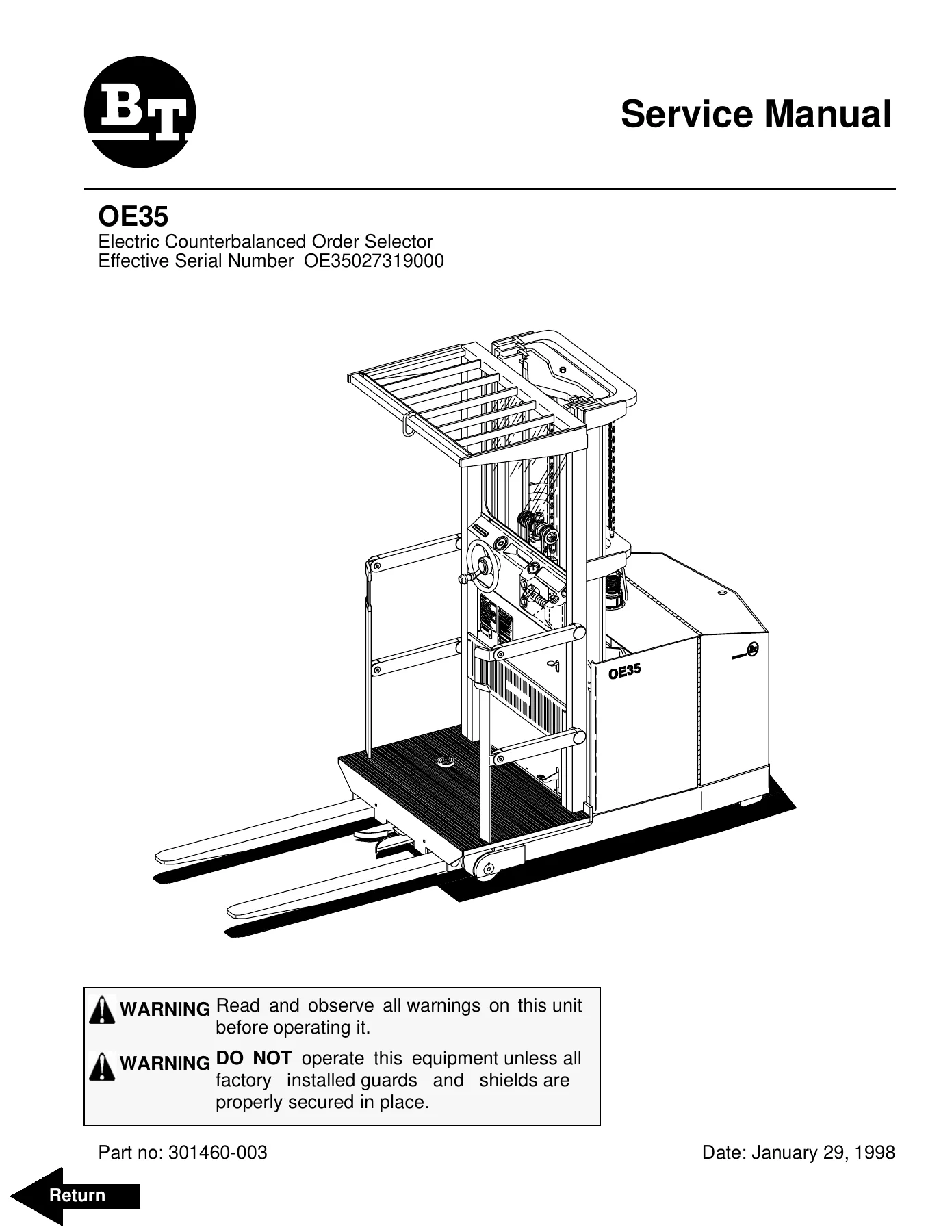
BT Prime-Mover OE35 Order Selector Service Manual - 24V and 36V Order Picker Repair Guide β€” PDF page 1 preview
BT Prime-Mover OE35 Order Selector Service Manual - 24V and 36V Order Picker Repair Guide β€” PDF page 24 preview
BT Prime-Mover OE35 Order Selector Service Manual - 24V and 36V Order Picker Repair Guide β€” PDF page 91 preview

The manual is delivered as an instant PDF download after payment. No shipping, no waiting for a parcel, no postage costs. Open it on a laptop, tablet or phone in the workshop, print the pages for the job you are doing, and keep the file on hand for the next one.
Reviews

There are no reviews yet.

Be the first to review “BT Prime-Mover OE35 Order Selector Service Manual – 24V and 36V Order Picker Repair Guide”

What Our Customers Say

β˜…β˜…β˜…β˜…β˜… Live reviews from customers
Loading customer reviews...
0
    0
    Your Cart
    Your cart is emptyReturn to Shop
    πŸ›’
    Recently Purchased
    πŸ•’ verified order