
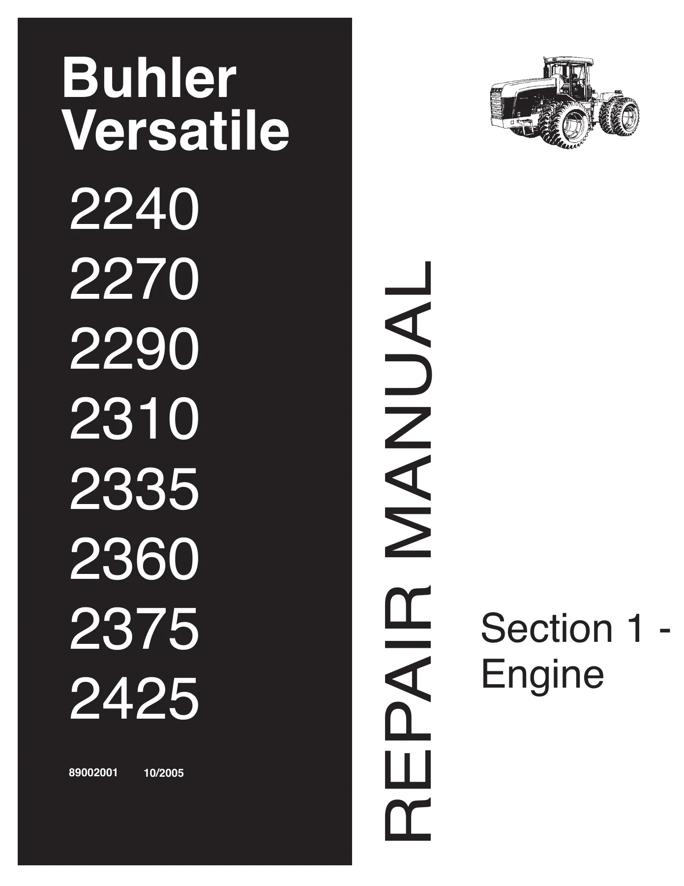
Buhler Versatile 2240 2270 2290 2310 2335 2360 2375 2425 4WD Tractor Repair Manual – Engine Section 1
Original price was: $29.95.$17.95Current price is: $17.95.
Engine Section 1 of the Buhler Versatile 4WD tractor repair manual (doc 89002001, 10/2005) covering the Cummins C8.3, M11 and N14 diesels – air induction, exhaust, engine removal and installation, cooling system, specifications, troubleshooting and repair times.
Description
The Buhler Versatile 2240 2270 2290 2310 2335 2360 2375 2425 4WD Tractor Repair Manual – Engine Section 1 is the complete engine volume of the Buhler Versatile 4WD service literature, issued under document number 89002001 and dated 10/2005. Every procedure inside it is built around the Cummins diesel engines fitted to these tractors, and the section moves through the air induction system, the exhaust system, engine removal and installation, and the full cooling system, backing each one with specifications, troubleshooting charts and individual repair times.
File Details
- Manual type: Repair / service manual – Section 1, Engine
- Brand: Buhler Versatile
- Models covered: 2240, 2270, 2290, 2310, 2335, 2360, 2375, 2425 4WD tractors
- Engines covered: Cummins C8.3, Cummins M11, Cummins N14
- Document number: 89002001
- Date: 10/2005
- Language: English
- Format: PDF
What the Engine Section Covers
The manual is divided into four systems, and each one follows the same practical pattern: a description and operation chapter, a specification chapter, removal and repair of components, and a repair time table so a job can be quoted before a wrench is lifted.
Air Induction System
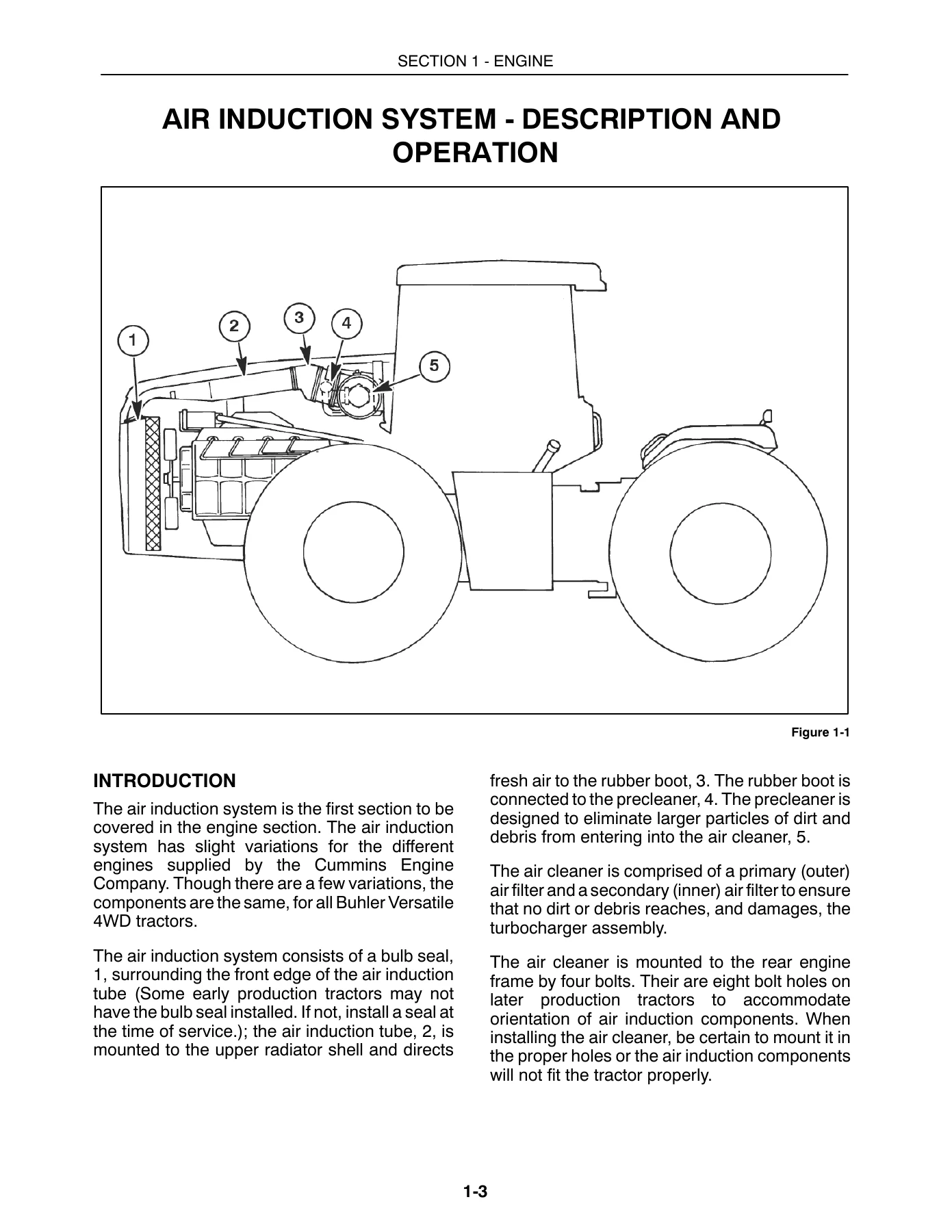
- Description and operation of the induction tube, bulb seal, rubber boot, precleaner and air cleaner
- Specifications including precleaner type, filter configuration and air flow at 2100 rpm for each model
- Removal, inspection and installation of the air induction tube, rubber boot, precleaner and air cleaner
- Air cleaner disassembly, inner and outer filter service, and inspection of the sealing surfaces
- Air cleaner to turbocharger pipe work procedures broken out separately for the 2240 (C8.3), the 2270 and 2310 (M11), and the 2360 and 2425 (N14)
- Repair time for individual components
Exhaust System
- Description and operation of the flex pipe, turbo to muffler pipe work, aspirator tube and muffler with heat shield
- Exhaust specifications including muffler type and exhaust air flow at 2100 rpm
- Turbo to muffler pipe work removal, disassembly, inspection, reassembly and installation for both the C8.3/M11 layout and the N14 layout
- Aspirator tube removal, disassembly, inspection and installation at the precleaner and muffler ends
- Muffler removal, extension pipe service, inspection and reinstallation on the right hand fender
- Band clamp torque values and antiseize application points for the exhaust joints
Engine
- Description and operation, including engine identification plate locations for the C8.3, M11 and N14
- Engine specifications: bore and stroke, displacement, compression ratio, firing order, lubrication pressures and oil flow, fuel consumption, idle speeds and torque figures
- Troubleshooting charts for hard starting, rough running, low power, knocks, low oil pressure, oil consumption, overheating, excessive fuel consumption and warning lights
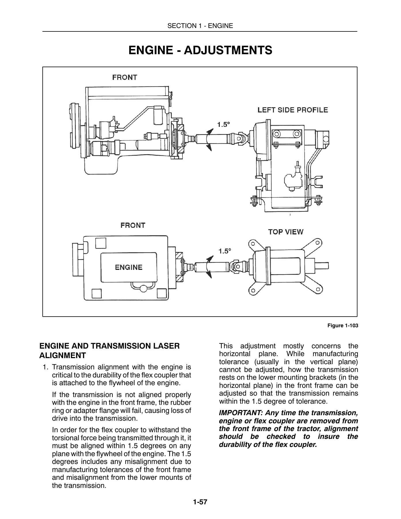
- Engine and transmission laser alignment procedure using alignment tool BLR20072, including target quadrants and the 1.5 degree tolerance
- Full engine removal and installation for the 2240 (C8.3), the 2270 and 2310 (M11), and the 2360 and 2425 (N14) electronic engines, step by step
- Repair time for engine removal and installation by model
Cooling System
- Description and operation of the radiator, expansion tank, surge hose, air bleed hose, fan and shroud
- Special tools for cooling system testing, including the coolant test kit, leak test kit and refractometer
- Cooling system specifications: coolant capacity, radiator core size, fins per inch, rows, fan diameter and blade width, pressure cap settings and thermostat opening temperatures
- Troubleshooting and testing, with the protection level test, DCA4 protection level test and cooling system leak test
- Removal and repair of the coolant hoses, fan and shroud, and radiator
- Repair time for individual components
Model and Engine Coverage in Detail
The engine chapter states the tractor-to-engine relationship plainly, which is useful when ordering parts or booking a machine in. The 2240 runs the Cummins C8.3 at 240 horsepower, classified as a mechanical engine. The 2270 and 2310 use the Cummins M11 at 270 and 310 horsepower respectively, also mechanical. The 2360 and 2425 step up to the Cummins N14 at 360 and 425 horsepower, and both of those are electronic engines. Displacement, bore and stroke, compression ratio, peak torque and CPL numbers are all tabulated for each engine, so the specification tables can be matched directly to the engine in the frame rather than guessed at.
Engine and Transmission Laser Alignment
One of the more distinctive procedures in this engine section concerns the flex coupler between the flywheel and the transmission. The manual explains that alignment must hold within 1.5 degrees on any plane or the rubber ring and adapter flange will fail and drive will be lost. It then walks through the BLR20072 laser alignment tool in detail – the holder, the target plates for the 12 x 4 and 12 x 2 Powershift transmissions, the 110 V adapter, the cover plate and foam, the capscrew sizes for each model, and the sequence for reading the beam against the correct quadrant. Adjusting the lower transmission mounts with a jack and wooden block, rechecking the beam, and the final torque figures are all spelled out, along with the reminder to check alignment any time the transmission, engine or flex coupler is removed.
How the Procedures Are Built
Removal steps in this Buhler Versatile 4WD tractor repair manual are numbered and illustrated, and the illustrations are keyed with callout numbers that match the text – bolt patterns, clamp positions, hose routing and lifting points are all shown rather than described in the abstract. Safety warnings appear at the head of each repair group, covering hot exhaust components, hot pressurized coolant, and the requirement to let the engine cool before starting work. Torque values are given in both metric and imperial units, and where a step depends on a measurement – such as setting the engine speed transducer half a turn off the ring gear teeth – the manual gives the exact figure.
The service information also flags the work that is not meant to be done in the field. Internal engine repair, fuel injection system work and turbocharger concerns are directed to an authorized Cummins dealer or distributor, and the manual is clear that the Engine Identification Plate information – engine number, engine family and CPL number – should be supplied when making that contact. Fuel injection system adjustment outside manufacturer specification is called out as voiding the warranty. That boundary is worth knowing before a machine is torn down.
Who This Manual Suits
Owners running a Versatile 4WD tractor who want to handle induction, exhaust, cooling and engine removal work themselves will find the procedures complete enough to follow directly. Shops that service these tractors get the specification tables, troubleshooting charts and repair times in one place, which makes quoting and diagnosing faster. Because the engine section also documents every Buhler Versatile component that mounts to the Cummins engine and must come off before the engine can be shipped out, it is equally useful as a teardown guide for a dealer-bound engine rather than only as an in-frame repair reference.
Get the Engine Section and Start the Job
With this Buhler Versatile 2240 2270 2290 2310 2335 2360 2375 2425 4WD Tractor Repair Manual – Engine Section 1 on hand, the jobs it supports run from a routine air filter and precleaner service through to pulling a C8.3, M11 or N14 out of the frame, and from diagnosing an overheating complaint to flushing the cooling system and testing the DCA4 additive level. Correct torque values, correct clamp sequences and the correct alignment tolerance are what separate a repair that holds from one that comes back – and having the manufacturer’s own procedures in front of you is the cheapest insurance against an expensive comeback. The file is a PDF delivered instantly after payment, with no shipping and no waiting, readable on a phone, tablet or laptop in the workshop and printable if you prefer paper pages on the bench next to the tractor.
IMAGES PREVIEW

Reviews
There are no reviews yet.