
New Holland 8160 8260 8360 8560 Tractor Repair Manual – Section 2 Electrical System Supplement PDF
Original price was: $39.95.$26.95Current price is: $26.95.
Section 2 Electrical System Supplement for New Holland 8160, 8260, 8360 and 8560 tractors – 280 pages of wiring diagrams, EMU error codes, harness layouts and component test values for every sensor, switch and solenoid on the machine.
Description
New Holland 8160, 8260, 8360, 8560 Tractor Repair Manual – Section 2 Electrical System Supplement
This dedicated electrical system supplement gives technicians the complete diagnostic and service documentation for the New Holland 8160, 8260, 8360 and 8560 tractors, plus the M100, M115, M135 and M160 variants referenced in the wiring diagram sections. It is Section 2 of the tractor repair manual and concentrates entirely on the electrical architecture – component location, harness routing, wiring schematics, the Electronic Management Unit, and every sensor, switch, solenoid and potentiometer that keeps these tractors running.
File Details
- Manual type: Tractor Repair Manual – Section 2 Electrical System Supplement
- Brand: New Holland
- Models covered: 8160, 8260, 8360, 8560 (wiring diagram sections also reference M100, M115, M135, M160)
- Document number: 86588680
- Language: English
- Page count: 280 pages
- File format: PDF
- Serial coverage: Both below and above SN 098954
Chapters Covered
- Component Location
- Wiring Diagrams (Below SN 098954)
- Electrical Introduction (Above SN 098954)
- Electronic Management Unit (Above SN 098954)
- Electronic Management Unit Error Codes
- Electrical Harnesses (Above SN 098954)
- Wiring Diagrams (Above SN 098954)
Component Location
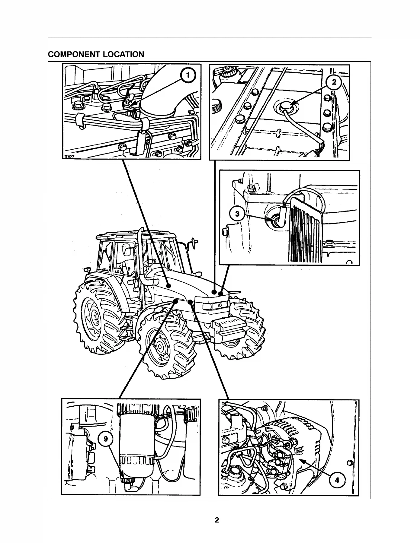
The opening section maps every electrical component on the tractor with numbered photographic callouts – cold start, coolant level sensor, coolant temperature sender, alternator, engine oil pressure switch and sender, air filter restriction switch, batteries, water-in-fuel sensor, diff lock and 4WD pressure switches, transmission oil pressure switch, brake fluid level switch, handbrake switch, fuel sender, PTO speed sensor, forward/reverse shuttle lever, clutch pedal potentiometer and disconnect switch, radar, range potentiometers, transmission speed sensors, dual command and range command selector levers, PWM valves A through E, the transmission side cover solenoids for range, PTO, diff lock and 4WD, CCLS pump switches, steering angle potentiometer, brake switches, transmission oil temperature sender, load sensing pins, lift lever potentiometer, EDC raise and lower solenoids, and the lift arm potentiometer. Every numbered callout corresponds directly to the diagnostic chapter that follows.
Wiring Diagrams – Below SN 098954
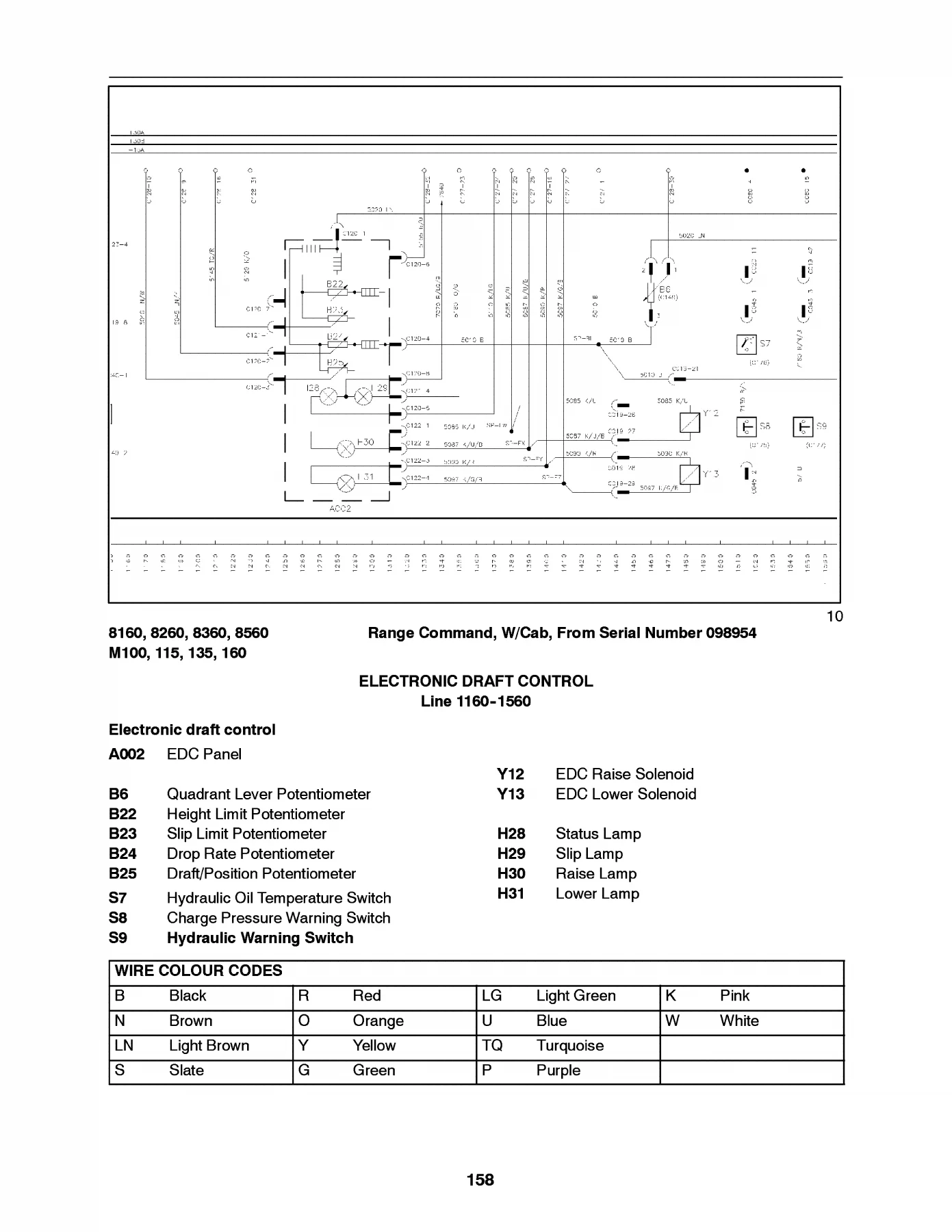
Tractors built before serial number 098954 use a distinct electrical architecture. This section provides the complete wiring schematics for those earlier machines, laid out in the same linear reference style used throughout the supplement. Fuse ratings, relay pin-outs, connector references (C-codes) and wire colour codes are printed alongside the diagrams. The wire colour chart covers B (black), N (brown), R (red), G (green), Y (yellow), O (orange), U (blue), W (white), LG (light green), LN (light brown), K (pink), TQ (turquoise), S (slate) and P (purple), so you can trace a circuit from battery positive through every fuse, switch and connector to the ground point without guessing.
Electrical Introduction – Above SN 098954
For tractors from serial 098954 onward, the introduction covers the three instrument cluster options (Electronic Instrument Cluster EIC, Analogue/Electronic Instrument Cluster AEIC, and Analogue Instrument Cluster AIC), the five-position key start switch (thermostart, off, accessory, warning and instruments, start), the two battery options (standard 1 x 1200 CCA, cold start 2 x 900 CCA), the main distribution panel layout behind the right-hand console side panel, the maxi fuse bank behind the left-hand panel, and the complete fuse and relay chart with amperage ratings from 5A through 30A. Relay functions are listed by letter – A for air brakes (Germany / with cab only), B through E for worklamp circuits, F for fuel shut-off, G for stoplamp, H for trailer brake, I for ignition and J for the hydraulic diverter valve.
Electronic Management Unit – Above SN 098954
The EMU chapter details the three variants (with cab with Terralock, with cab without Terralock, less cab without Terralock), the touch-pad layout for auto and manual 4WD, auto and manual diff lock and the worklamp controls. Operating logic for auto diff lock, manual diff lock, auto FWD and manual FWD is explained with the exact speed and steering angle thresholds – the diff lock releases temporarily when brakes are applied, when steering exceeds 20 degrees below 10 km/h, when steering exceeds 10 degrees between 10-15 km/h, or when the raise/work switch is operated, and permanently above 15 km/h. Auto FWD disengages above 20 km/h, when steering exceeds 25 degrees between 10-20 km/h, or above 35 degrees below 10 km/h. The chapter also covers the Terralock calibration procedure for the wheel speed sensor and steering angle sensor using a 100-metre test track and the touch-pad entry sequence.
Electronic Management Unit Error Codes
A complete diagnostic code table sorted by priority, from P01 (rear PTO brake solenoid stuck off, highest priority) through P32 (steering sensor out of range – minimum voltage). Codes P07 and P08 cover rear PTO solenoid faults, P11 and P12 the front PTO, P15 through P18 the diff lock, P21 through P24 the FWD system, and P27 the PTO speed sensor open circuit. Each entry states what the fault means in plain terms so you can choose the right diagnostic path before opening a flowchart. The diagnostic flowcharts that follow walk through connector-by-connector checks at C105 (EMU), C19, C33, C41, C42, C54, C116, C155 and C169, with resistance thresholds (typically 5-11 ohms at 20 C for solenoid coils), short-to-ground and short-to-12V tests, and the decision tree for substituting the EMU itself.
Electrical Harnesses – Above SN 098954
Harness routing diagrams for the front main (engine) and lighting harness, rear main harness for dual command with and without cab, chassis harness for range command semi-powershift, chassis harness for dual command, rear main harness for range command with cab, and cab main harness. Each connector is labelled with its C-code (C001 through C158 plus the EMU C105 and cluster C079-C081), the wire colours entering each pin, and a reference back to the component location section so harness, connector and component all line up.
Component Testing – Voltage, Resistance and Frequency
Every electrical component in the supplement gets a test procedure with exact voltage, resistance or frequency values:
- Thermostart: 12 V between BROWN/RED and ground for 20 seconds with the key turned counter-clockwise
- Coolant level sensor: 12 V between BLACK/ORANGE and BLACK; 0.22 ohms when the level is correct
- Coolant temperature sender: 5 V or less at the GREEN/BLUE wire; 4500-6000 ohms cold, under 650 ohms hot
- Alternator: 142.5-855 Hz square wave (480-3060 RPM); check at the WHITE/SLATE W terminal
- Engine oil pressure switch: trips below 0.68 bar (10 PSI); 12 V at the WHITE/BROWN wire
- Engine oil pressure sender: 5 V supply; 26 kilohms between pins A and B, 34 kilohms between B and C
- Air filter restriction switch: triggers at 46.7 mm Hg (25 in. H2O)
- Water-in-fuel sensor: 12 V at the BLACK wire; immersion in grounded water illuminates the lamp
- Differential lock pressure switch: 16 bar (240 PSI) engagement; 12 V between YELLOW/BLACK and BLACK
- 4WD pressure switch: 16 bar (240 PSI); 12 V between YELLOW/BLUE/SLATE and BLACK
- Low transmission oil pressure switch: trips below 11 bar (160 PSI)
- Brake fluid level switch: 12 V between PINK/RED/BLACK and PURPLE/YELLOW; open circuit when level is correct
- Handbrake switch: 5 V at BLACK and RED/PINK with C136 disconnected, 12 V with key on
- Fuel gauge: 5-7 V supply; 31-49 ohms full, 230-250 ohms empty
- PTO speed sensor: 5 V at BLACK/ORANGE/SLATE; 660-680 ohms between pins; frequency table from 400 RPM (8 Hz) to 1000 RPM (200 Hz)
- Forward/reverse shuttle lever: resistance tables for forward, neutral and reverse positions across pins 1-6
- Clutch pedal potentiometer: 5 V at LIGHT BROWN; voltage on YELLOW/RED/BLACK drops from 5 V to 0 V as the pedal is depressed; resistance table across orange, green and black wires
- Clutch pedal disconnect switch: continuity between pins 2 and 3 when released, pins 1 and 4 when pressed; 0.75 V at pins 2 and 4 with ignition on
- Radar: 4-pin harness (ground, frequency signal, supply, diagnostics) with frequency-to-speed relationship
- Range potentiometers: 8 V supply; resistance values at rest and full travel
- Transmission speed sensors: 800-1200 ohms between pins 1 and 2
- Dual command HI/LO selector: continuity table for neutral, tortoise and hare positions
- Range command selector: 2.7-2.8 ohms released, 560 ohms pressed for upshift, downshift and range buttons
- PWM solenoid valves A-E: 8-11 ohms coil resistance; 500 Hz supply frequency; average 8 V / 370 mA on clutches A and B, 7.3 V / 800 mA on C, D and E
- Pressure switches A and B (Dual Command): 12 V at TURQUOISE/BROWN/BLACK (A) and GREEN (B) wires with key on
- Forward/reverse synchronizer potentiometer: 5 V at LIGHT BROWN; 1000 ohms to 3.7 kilohms between GREEN and ORANGE
- Transmission side cover solenoids: 6-8 ohms coil resistance; 12 V differential lock, PTO, PTO brake, 4WD and dump valve logic detailed
- 40 C CCLS switch: normally open; closes above 40 C (104 F) to enable the intake filter restriction warning
- Intake filter restriction switch: normally open; 12 V between BROWN/BLACK and ground once oil is above 40 C
- Low charge pressure switch: normally closed; 12 V at RED/BROWN/BLACK; continuity to ground with engine off
- Steering angle potentiometer: 5 V at BLACK/GREEN/SLATE; 4.75 kilohms resistance between red/black and yellow/red at steering stop, 45 mm adjustment
- Brake switches: 12 V at GREEN wires; continuity between centre pins released, outer pins pressed
- Transmission oil temperature sender: 5 V at BLACK/GREEN; resistance table from 1140-1339 ohms at 0 C down to 285-334 ohms at 40 C
- Load sensing pins: 8.5 V supply; 9170 ohms between pins 1 and 3, 178 ohms between 1 and 2 or 2 and 3
- Lift lever potentiometer: 5.3 V at BROWN; resistance changes from 1.28 kilohms forward to 2.95 kilohms rearward
- EDC raise and lower solenoids: 6-8 ohms; 83 Hz signal frequency
- Lift arm (cross shaft) potentiometer: 5 V at LIGHT BROWN; resistance table from arms lowered to raised
Who This Manual Is For
If you own, operate, service or maintain any of the New Holland 60-series tractors – 8160, 8260, 8360 or 8560 – and the electrical system is giving you trouble, this is the reference that tells you exactly which wire, which connector and which component to test, what value to expect, and which error code points where. Whether you are chasing an intermittent fault in the transmission harness, diagnosing a P15 diff lock code, replacing the alternator, setting up the steering angle potentiometer after a repair, or calibrating the EMU on a 100-metre track, the values and procedures here replace guesswork with measured facts.
Why a Dedicated Electrical Supplement Matters
Electrical faults are the hardest thing to diagnose on any modern tractor because the circuit runs through multiple harnesses, connectors, fuses and processors, and a single bad ground can look like a failed sensor. This supplement is the shortcut. It gives you the serial-number break point (098954) so you know which diagram set applies to your machine, the wire colour code so you can identify any conductor at a glance, the C-code connector reference so you can find the right plug on the right harness, and the exact voltage, resistance or frequency threshold the component should show. Without those three things – correct diagram, correct connector, correct value – you are swapping parts and hoping. With them, you are diagnosing.
IMAGES PREVIEW
Get the New Holland 8160 8260 8360 8560 Electrical System Repair Manual as an Instant PDF Download
Delivered as a printable PDF instantly after purchase – no shipping, no waiting, no lost paper copy. Open it on a laptop in the workshop, a tablet under the cab, or print the pages you need and take them to the machine. Every diagram, table, error code and test procedure in this 280-page Section 2 Electrical System Supplement is laid out for quick reference on the job. Order now and have the complete New Holland tractor electrical repair manual on your device in minutes.
Reviews
There are no reviews yet.