★ TRUSTED BY 321,897+ PROFESSIONALS WORLDWIDE
🏒
Trusted Business
Verified & Licensed
πŸ›‘οΈ
Virus Free Files
100% Safe Downloads
πŸ”’
Secure Payment
SSL Protected
⚑
Instant Delivery
Available Immediately
Sale!

Canon CXDI-401G / CXDI-401C Wireless Service Manual – PDF Download

Original price was: $34.95.Current price is: $19.95.

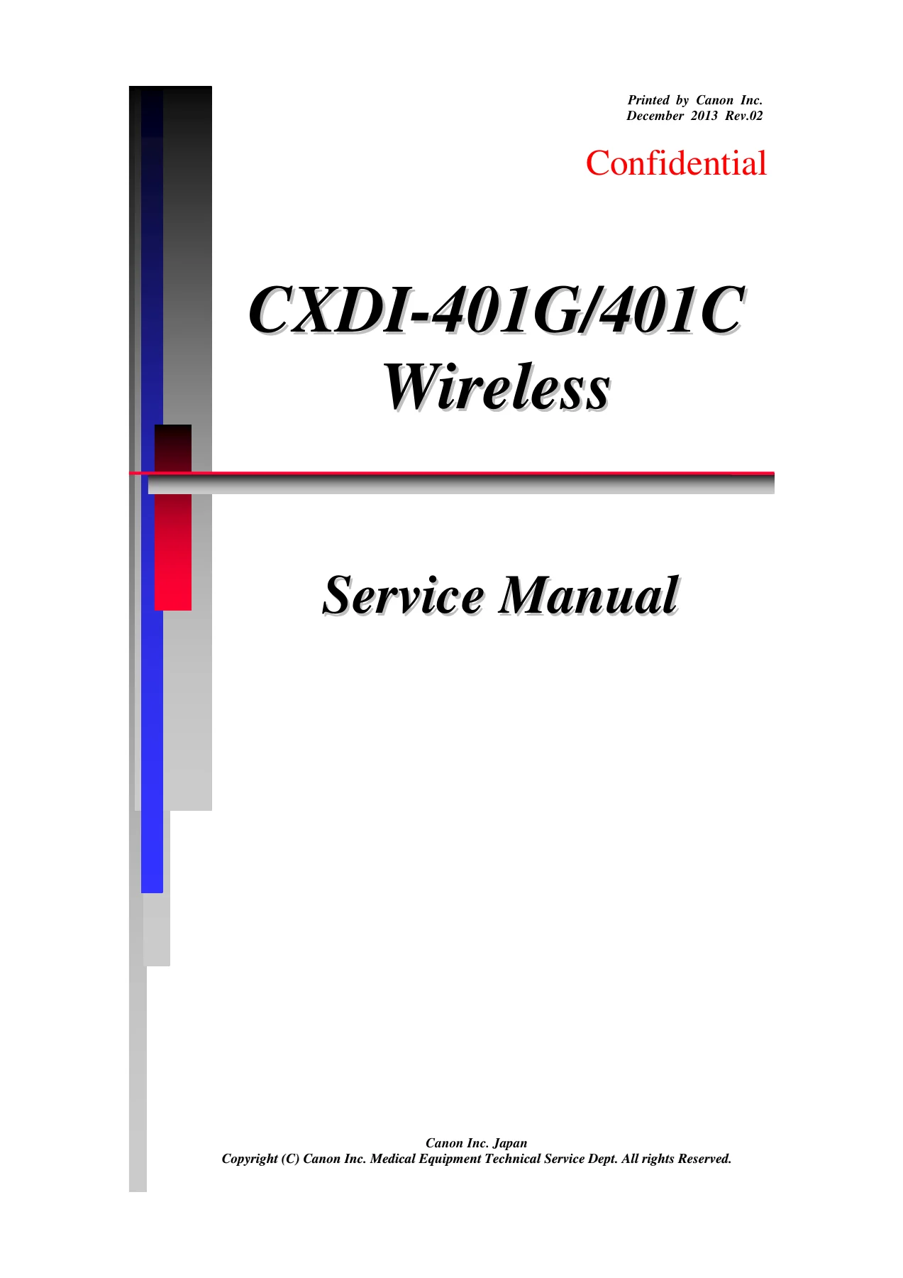
Complete 241-page Canon CXDI-401G and CXDI-401C Wireless Service Manual (Rev.02, December 2013) covering installation, functions, repair, parts catalog, and troubleshooting for the Canon CXDI wireless DR system.

⚑
Instant PDF Download
Available immediately
πŸ’Ύ
Save to Your Device
Download & keep forever
πŸ›‘οΈ
Antivirus Scanned
100% virus-free
🌍
Trusted Worldwide
175,000+ customers

Description

Canon CXDI-401G / CXDI-401C Wireless Service Manual

This is the complete Canon CXDI-401G / CXDI-401C Wireless Service Manual β€” the full 241-page PDF service document published by Canon Inc. for its wireless flat panel detector DR system. Whether you are a trained service engineer, a medical imaging technician, or a sales company working with CXDI Wireless hardware, this manual places the entire Canon service documentation set in your hands as one PDF reference file.

File Details

  • Manual Type: Service Manual
  • Brand / Manufacturer: Canon Inc.
  • Model Coverage: CXDI-401G Wireless, CXDI-401C Wireless (2.4 GHz / 5 GHz)
  • Language: English (with a German safety page)
  • Page Count: 241 pages
  • File Format: PDF
  • Revision: Rev.02
  • Publication Date: December 2013
  • Document Title: CXDI-401G/401C Wireless Service Manual

Chapters Covered in the CXDI-401G / CXDI-401C Wireless Service Manual

The manual is organized into nine chapters, following the structure Canon uses across the CXDI service documentation set:

  • 1. Overview β€” System configuration, operation modes (standard synchronization vs. non generator connection), component lists, image processing flow, and full specifications including detector, wireless communication, batteries, chargers, and grid data.
  • 2. Installation Procedures β€” Work precautions, installation restrictions, product configuration, packing list, tool list, system connection diagrams for standard synchronization and non generator connection modes, wireless/wired linking, calibration, image quality checks, and post-installation checks.
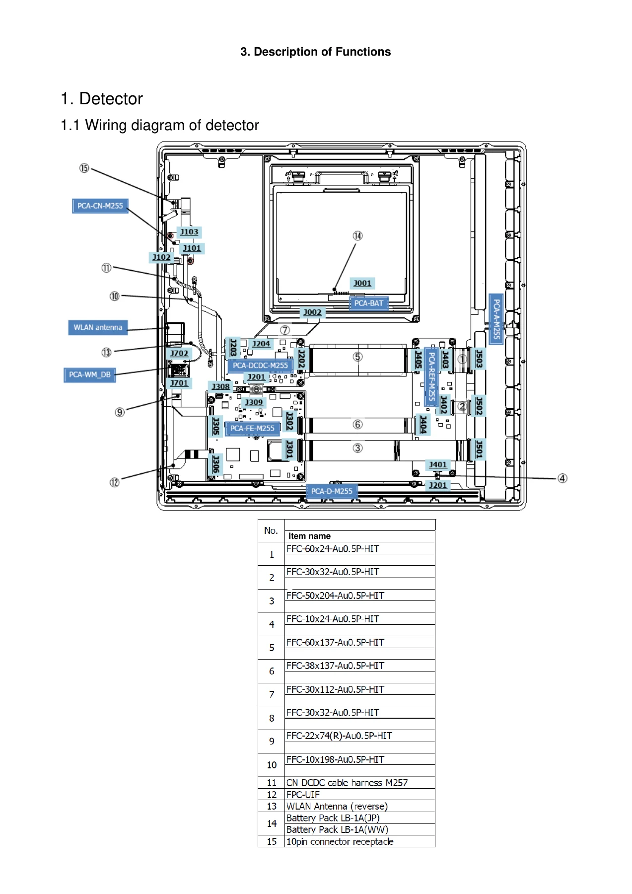
  • 3. Description of Functions β€” Detector board-level descriptions (PCA-FE-M255, FPC-UIF, PCA-WM-DB, PCA-CN-M255, PCA-DCDC-M255, PCA-BAT, PCA-REF-M255), X-ray interface box PCA-XIF board, wiring unit PCA-PB-M255 board, and ready indicator unit.
  • 4. Repair Guide β€” Disassembly and reassembly of the X-ray interface box and wiring unit, PCA replacement procedures, firmware and FPGA updating/recovery for the PCA-FE-M255 and PCA-XIF boards, and post-replacement work lists.
  • 5. Parts Catalog β€” Illustrated parts breakdowns for the detector unit, X-ray interface box (XB-1A), wiring unit (WU-3A), and ready indicator unit (RI-3A).
  • 6. Troubleshooting β€” Primary, secondary, and tertiary response flows, wireless communication troubleshooting, channel setting guidelines, error handling on GUI, and data collection procedures.
  • 7. Service Manual Report β€” Supplementary service manual reporting procedures.
  • 8. Tools β€” Special tool list including the audit_grid_NE_RF.exe grid angle measurement tool.
  • 9. Appendix β€” Installation inspection check sheet covering wireless environment, battery, sensor unit, sensor recognition, X-ray interface box, wiring unit, calibration, self-diagnosis, performance test, image quality, control PC, and final checks.

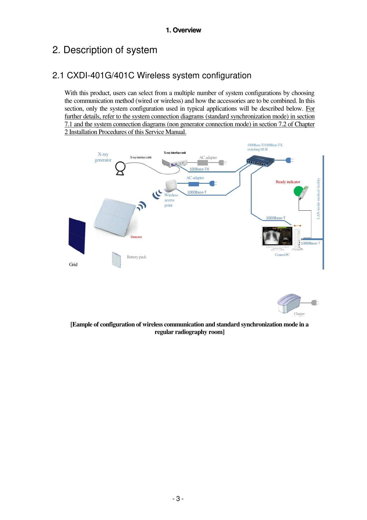
Beyond the chapter breakdown, the real value of this Canon CXDI-401G/401C Wireless service manual lies in the depth of its technical reference material. It contains the system connection diagrams for standard synchronization and non generator connection modes across regular radiography rooms and mobile X-ray systems, board-level functional descriptions that identify exactly which PCB handles which task, and the full specifications set that governs everything from detector weight and pixel pitch to wireless channel bonding rules by country. That is what makes this manual useful for people who actually have to install, calibrate, service, or support this equipment β€” not just for reference reading.

Specifications and Coverage

The specifications section alone covers a wide range of operational data: the 41.5 cm Γ— 42.6 cm effective imaging range, 125 ΞΌm pixel pitch, wireless IEEE802.11n on 2.4 GHz and 5 GHz bands, wired 100Base-TX / 1000Base-T options, exposure timing windows, battery performance in max and average modes, charging times, environmental resistance values, and full battery charger ratings. The manual also documents the country-by-country regulatory settings for wireless operation β€” useful when a single service manual needs to support installations across multiple regions.

For the non generator connection mode, the manual explains the imaging flow end to end: how the detector detects X-rays and takes images without synchronization to the X-ray generator through the X-ray interface box, the exposure timing rules, the calibration procedure when non generator connection settings are enabled, and the conditions under which image artifacts or detection failures can occur.

What This Canon CXDI Service Manual Enables You to Do

This is the manual that covers the CXDI-401G Wireless and CXDI-401C Wireless DR system across its entire service lifecycle. With it, a trained service technician can:

  • Set up and configure the detector, access point, X-ray interface box, wiring unit, and ready indicator on both standard synchronization and non generator connection modes.
  • Perform infrared and wired linking (sensor registration), including IP address assignment and re-linking procedures.
  • Run calibration, performance testing, and self-diagnosis through the CXDI Control Software NE service tools.
  • Diagnose and remedy wireless communication trouble, link failures, error codes, and image quality problems.
  • Disassemble and reassemble the X-ray interface box and wiring unit, replace PCBAs, and re-apply thread-locking adhesive to specified torque values.
  • Update and recover firmware and FPGA data on the PCA-FE-M255 and PCA-XIF boards, including backup mode boot recovery.
  • Identify the correct spare parts for the detector, X-ray interface box, wiring unit, and ready indicator using the parts catalog.
  • Verify system performance after installation using the inspection check sheet in the appendix.

Correct service procedures and specifications matter in medical imaging because the margin for error is narrow. Detector calibration that is performed with the wrong exposure conditions, wireless channel settings that clash with other equipment in the room, or incorrect board replacement procedures can all compromise image quality, patient safety, or the reliability of the DR system. Having the complete service manual on hand lets you follow the same procedures and reference the same specifications that Canon published for its service network.

Complete PDF Bookmark Tree

Complete Bookmarks

The complete bookmarks in the β€œCanon CXDI-401G / CXDI-401C Wireless Service Manual – PDF Download” are as follows:

CXDI-401G/401C Wireless Service Manual_Rev.02p. 1
Service Manual Introductionp. 2
Caution Regarding Servicep. 3
VORSICHTp. 4
Caution Regarding the Setupp. 5
1. Overviewp. 7
1. Overviewp. 9
2. Description of systemp. 11
2.1 CXDI-401G/401C Wireless system configurationp. 11
2.2 System compatibility with Canon’s existing wireless models maintainedp. 13
2.3 Operation modesp. 13
2.4 Restrictions on connectionsp. 14
2.5 Component listp. 15
3. CXDI image processingp. 16
3.1 Processing flowp. 16
3.2 Concerning each type of imagep. 16
4. Specificationsp. 17
4.1 CXDI-401G/401C Wireless specificationsp. 17
4.2 Power supply specificationsp. 20
4.3 Recommended LAN cable specificationsp. 20
4.4 Environmental resistance specificationsp. 20
4.5 Required PC specificationsp. 21
4.6 Wireless communication specificationsp. 21
4.7 Link communication specificationsp. 28
4.8 Detector LED display specificationsp. 29
4.9 Ready indicator display and notification tone specificationsp. 29
4.10 Battery and battery charger specificationsp. 31
4.11 Grid specificationsp. 34
4.12 Wiring unit (option)p. 36
4.13 [Supplementary notes] Long-term storage of batteriesp. 37
2. InstallationProcedures
1. Work-related precautionsp. 41
2. Installation restrictionsp. 41
3. Installation-related precautionsp. 42
4. Product configurationp. 46
5. Opening the packing boxesp. 52
6. Installation procedurep. 59
6.1 List of tools requiredp. 59
6.2 System installation proceduresp. 60
7. Installationp. 67
7.1 System connection diagrams (standard synchronization mode)p. 67
7.1.1 Standard synchronization mode (regular radiography room: wireless and wired)p. 67
7.1.2 Standard synchronization mode (regular radiography room: wireless)p. 68
7.1.3 Standard synchronization mode (regular radiography room: wired)p. 68
7.2 System connection diagrams (non generator connection mode)p. 70
7.2.1 Non generator connection mode (regular radiography room: wireless and wired)p. 70
7.2.2 Non generator connection mode (regular radiography room: wireless)p. 71
7.2.3 Non generator connection mode (regular radiography room: wired)p. 72
7.2.4 Non generator connection mode (mobile X-ray system: wireless)p. 73
7.2.5 Non generator connection mode (mobile X-ray system: wired)p. 74
7.3 System connections in the standard synchronization mode (wireless and wired)p. 75
7.3.1 System connectionsp. 75
7.3.2 Linking (recognizing/connecting) the detectorp. 80
7.3.3 Connecting to the X-ray interface box (XB-1A)p. 83
7.3.4 Wiring unit (WU-3A) connectionsp. 87
7.4 System connections in the standard synchronization mode (wired)p. 93
7.4.1 System connections (using the wiring unit)p. 93
7.4.2 Wired linkp. 93
7.5 System connections in the non generator connection mode (wireless and wired)p. 97
7.5.1 System connections (wireless and wired)p. 97
7.5.2 System connections (wired)p. 97
7.5.3 Overview of non generator connection imagingp. 98
7.5.4 Non generator connection mode settingsp. 100
7.5.5 Refresh buttonp. 102
7.5.6 Imaging in the non generator connection modep. 102
7.6 Calibration during non generator connection operationsp. 103
7.6.1 Calibration operation procedurep. 103
7.6.2 Performance test operation procedurep. 106
7.7 Confirming image capture during non generator connection operationp. 107
7.8 System connections in the non generator connection mode (mobile X-ray system environment: Japan)p. 111
7.8.1 System connections (wireless and wired)p. 111
7.8.2 Restrictionsp. 112
7.8.3 Setting procedurep. 113
7.8.4 AP LNK Configuration Tool Setting Procedurep. 122
7.8.5 Ethernet-USB adapter settingsp. 124
7.8.6 Setting for internal wireless LAN (for a wireless connection to the main LAN)p. 125
7.9 System connections in the non generator connection mode (mobile X-ray system environment: outside Japan)p. 126
7.9.1 System connections (wireless and wired)p. 126
7.9.2 Restrictionsp. 126
7.9.3 Settingsp. 127
7.9.4 System connection (for Europe and USAοΌ‰p. 131
7.9.5 Limitationsp. 132
7.9.6 Setting up of various factorsp. 133
7.10 Using the detector in multiple radiography rooms
7.11 When using an existing detector together with this DR Wireless systemp. 146
7.12 Interfacing with the X-ray generator (Standard synchronization mode)
7.12.1 Description of interface signals
7.12.2 Signals and their functions for connection with the X-ray generator
7.12.3 Ratings and performance of relay and photocoupler (mounted on PCA-XIF board)
7.12 Interfacing with the X-ray generator (Standard synchronizationmode)p. 147
7.12.1 Description of interface signalsp. 147
7.12.2 Signals and their functions for connection with the X-ray generatorp. 149
7.12.3 Ratings and performance of relay and photocoupler (mounted on PCAXIFboard)p. 151
7.13 CXDI Control Software NE settingsp. 154
7.14 Image quality checksp. 155
7.15 Post-installation checksp. 157
7.16 Securing the ready indicator unitp. 158
7.16.1 Selecting where the unit is to be securedp. 158
7.16.2 How to secure the ready indicator unitp. 158
7.16.3 How to replace the fastener hook and fastener loopp. 160
8. Outline drawingsp. 161
3. Description of Functionsp. 168
1. Detectorp. 170
1.1 Wiring diagram of detectorp. 170
1.2 Loading the data of the images takenp. 171
1.3 Detectorp. 172
1.3.1 PCA-FE-M255 boardp. 172
1.3.2 FPC-UIF boardp. 172
1.3.3 PCA-WM-DB boardp. 173
1.3.4 PCA-CN-M255 boardp. 173
1.3.5 PCA-DCDC-M255 boardp. 173
1.3.6 PCA-BAT board (integrated with the battery holder)p. 173
1.3.7 PCA-REF-M255 boardp. 173
2. X-ray interface boxp. 174
2.1 Wiring diagram of X-ray interface boxp. 174
2.2 X-ray interface boxp. 175
2.2.1 PCA-XIF boardp. 176
3. Wiring unit (option)p. 177
3.1 Wiring diagram of wiring unitp. 177
3.2 Wiring unitp. 178
3.2.1 PCA-PB-M255 boardp. 179
3.2.2 AC/DC power supplyp. 179
3.2.3 Power cable assemblyp. 179
3.2.4 Detector cablep. 179
3.2.5 Status indicator unitp. 181
4. Ready indicator unit (option)p. 182
4.1 Overviewp. 182
4.2 Functionsp. 182
4. Repair Guidep. 183
1. Restrictions on disassembly and repair workp. 185
2. Precautionsp. 185
2.1 Repair and maintenance inspectionsp. 185
2.2 Removal of external coversp. 185
2.3 Confirmation after PCB replacementp. 185
3. Disassembly and re-assemblyp. 186
3.1 Detectorp. 186
3.2 X-ray interface boxp. 186
3.2.1 Removing the top coverp. 186
3.2.2 Replacing the PCA-XIF boardp. 187
3.2.3 Removing/attaching bottom surface PADp. 189
3.3 Wiring unitp. 190
3.3.1 Removing the top coverp. 190
3.3.2 Removing the cosmetic coverp. 191
3.3.3 Removing the inside cablesp. 193
3.3.4 Replacing the PCA-PB boardp. 195
3.3.5 Replacing the AC/DC power supplyp. 196
3.3.6 Replacing the B-type device mark labelp. 198
3.3.7 Removing and mounting the bottom panel padsp. 198
4. PCA-FE-M255 board firmware and FPGA updating and recoveryp. 199
4.1 PCA-FE-M255 board firmware and FPGA updatingp. 199
4.2 PCA-FE-M255 board firmware and FPGA recoveryp. 199
5. PCA-XIF board firmware updating and recoveryp. 201
5.1 PCA-XIF board firmware updatingp. 201
5.1.1 Introductionp. 201
5.1.2 Basic operations performed using web browserp. 201
5.1.3 Checking the firmware versionp. 202
5.1.4 Updating the normal codesp. 203
5.1.5 Checking after updating that the updating has been reflectedp. 204
5.1.6 (Reference) Updating the backup codesp. 204
5.1.7 (Reference) Concerning the PC and network connectionsp. 204
5.1.8 (Reference) Concerning telnet connectionsp. 204
5.2 PCA-XIF board firmware recoveryp. 205
5.2.1 Introductionp. 205
5.2.2 Forced backup boot operationp. 205
5.2.3 Concerning ARP clear for the PCp. 206
5.3 Other reference informationp. 207
5.3.1 Changing the IP address of the PCA-XIF boardp. 207
5.3.2 Obtaining the PCA-XIF board logp. 208
6. Work accompanying replacement of partsp. 209
5. Parts Catalogp. 210
Detector unitp. 212
X-ray interface box unit (XB-1A)p. 213
Wiring unit (WU-3A)p. 215
Ready Indicator unit (RI-3A)p. 217
6. Troubleshootingp. 218
Action taken to remedy DR Wireless SYSTEM troublep. 220
1. Troubleshooting flowp. 221
2. Primary responsep. 222
3. Secondary responsep. 227
4. Collecting data when trouble has occurredp. 229
5. Precautions for performance test and self-diagnosis imagingp. 232
7. Service Manual Reportp. 235
8. Toolsp. 236
SPECIAL TOOL LISTp. 237
9. Appendixp. 238
Inspection Check Sheetp. 239


IMAGES PREVIEW

Canon CXDI-401G / CXDI-401C Wireless Service Manual - PDF Download β€” PDF page 1 preview
Canon CXDI-401G / CXDI-401C Wireless Service Manual - PDF Download β€” PDF page 11 preview
Canon CXDI-401G / CXDI-401C Wireless Service Manual - PDF Download β€” PDF page 170 preview

Instant PDF Delivery

The Canon CXDI-401G / CXDI-401C Wireless Service Manual is delivered as an instant PDF download immediately after purchase β€” no physical shipping, no waiting. The file can be opened on any computer, laptop, tablet, or smartphone, and pages can be printed for use in the field or in a workshop. That makes it practical for a service engineer working across multiple sites, a sales company technician preparing an installation, or a medical engineer keeping reference documentation on hand for equipment they support.

If you work on Canon CXDI wireless DR hardware, this is the reference document you want on the shelf β€” or in your pocket.

Reviews

There are no reviews yet.

Be the first to review “Canon CXDI-401G / CXDI-401C Wireless Service Manual – PDF Download”

What Our Customers Say

β˜…β˜…β˜…β˜…β˜… Live reviews from customers
Loading customer reviews...
0
    0
    Your Cart
    Your cart is emptyReturn to Shop
    πŸ›’
    Recently Purchased
    πŸ•’ verified order