
Case 1850K Tier 3 Crawler Dozer Service Manual PDF – LT, XLT & LGP Repair Guide
Original price was: $69.95.$44.95Current price is: $44.95.
Complete Case 1850K Tier 3 Crawler Dozer Service Manual (Print 9-94100, 468 pages). Covers LT, XLT and LGP variants from HHA185LTN6HC49001, HHA185XTN6HC50001 and HHA185LPN6HC51001 onward — engine, transmission, final drives, brakes and steering, undercarriage, hydraulics, electrical and air conditioning.
Description
The Case 1850K Tier 3 Crawler Dozer Service Manual is the complete workshop repair guide for the LT, XLT and LGP variants of this machine, published under Print No. 9-94100. Across 468 pages it covers engine removal and overhaul, the full power-shift transmission, final drives, brakes and steering, undercarriage, dozing hydraulics, the electrical system and the air conditioning unit — the same procedures a Case service technician follows in the workshop, with the torque values, test pressures, adjustment clearances and special tool part numbers called out at each step.
File Details
- Manual type: Service / Workshop Manual
- Brand: Case (CNH)
- Model: 1850K Tier 3 Crawler Dozer
- Variants: LT, XLT, LGP
- Language: English
- Document number: Print No. 9-94100
- Date: XI – 2006
- File format: PDF
- Page count: 468
Model and Serial Coverage
This 1850K Tier 3 service manual applies to machines from the following Product Identification Number ranges:
- 1850K LT: HHA185LTN6HC49001 et AFTER
- 1850K XLT: HHA185XTN6HC50001 et AFTER
- 1850K LGP: HHA185LPN6HC51001 et AFTER
The 1850K is powered by the Iveco 667TA – 6.7 direct-injection, turbocharged and after-cooled six-cylinder diesel. Net flywheel output (ISO 9249) is approximately 139 kW / 187 HP for the LT and XLT, and approximately 151 kW / 202 HP for the LGP, with rated speed at 2000 rpm across the range. All three variants share the same 3F/3R power-shift transmission, differential steering system, double-reduction final drives and oil-bath multiple-disc brakes — so the repair procedures in this manual cover the common platform while noting the dimensions and pressures specific to each undercarriage version.
Chapters Covered
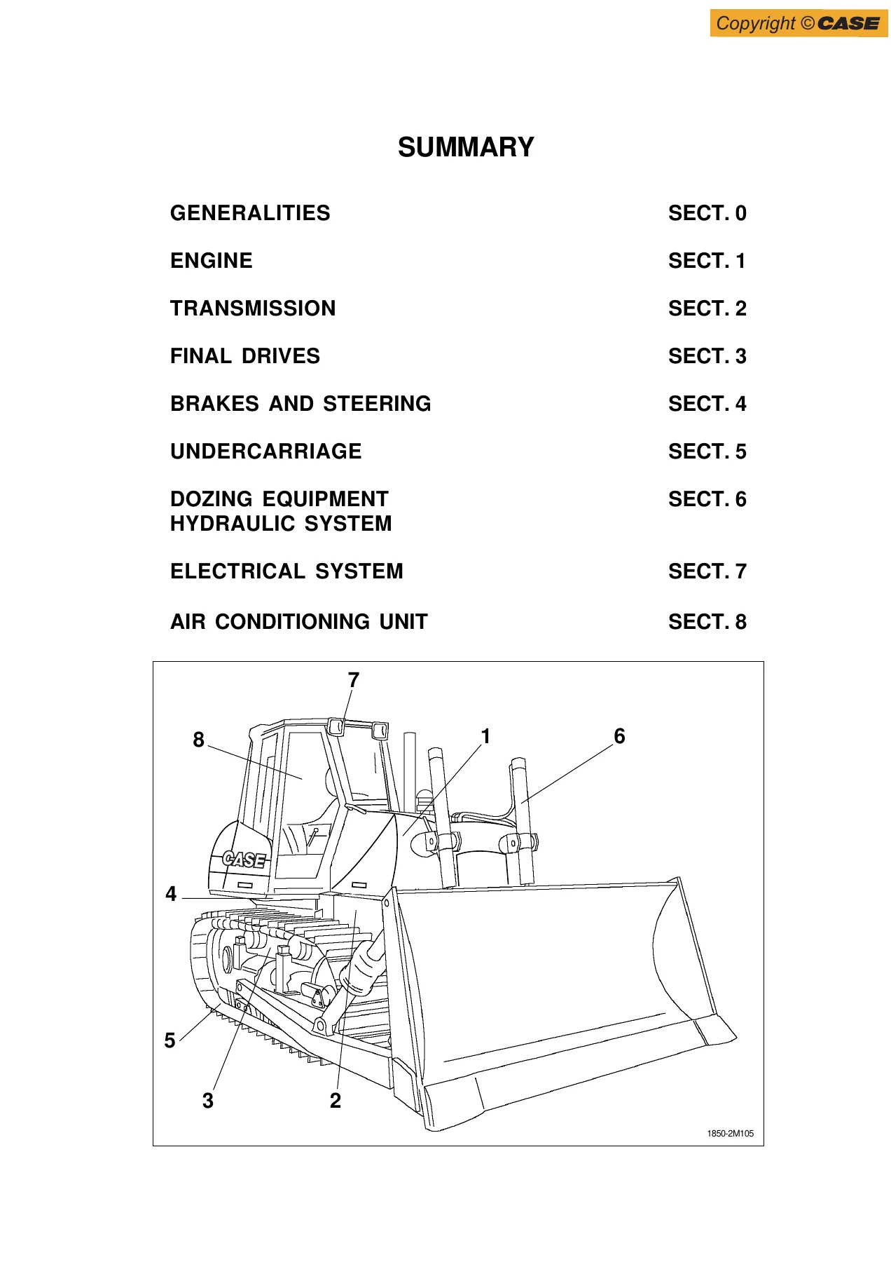
- Generalities
- Engine
- Transmission
- Final Drives
- Brakes and Steering
- Undercarriage
- Dozing Equipment Hydraulic System
- Electrical System
- Air Conditioning Unit
Generalities
Safety rules, identification data, tables of fluids used, main dimensions for the BD and PAT configurations, general technical data for the 1850K (LGP) and 1850K (LT/XLT), the weight table, stability diagrams with centre-of-gravity positions for blade and ripper combinations, general instructions on seal and O-ring installation and high-pressure pipe assembly, troubleshooting methodology, units of measure, and the complete tightening torque tables for standard components with strength classes and coating codes.
Engine
General specifications for the Iveco 667TA – 6.7, engine data (net flywheel power, torque, valve clearance, firing order 1-5-3-6-2-4, counterclockwise rotation), left/right/front/rear engine diagrams, then the complete engine and converter removal and installation procedure — draining coolant, removing the hood, panels, cab tilting, radiator, silencer and converter in sequence, with torque values for every securing screw. The engine section also covers blink-code diagnostics for the engine ECU, including the full fault code list with DT-C codes, dial lamp behaviour and descriptions.
Transmission
Description of the power-shift 3F/3R transmission and its torque converter hydraulic diagram, the transmission housing and propeller shaft, troubleshooting table, torque converter stall test, delivery pressure test procedure, converter safety valve pressure check (10.5 ± 0.5 bar), transmission gear-shifting electric control valve data, transmission setting using the BB3 instrument, complete disassembly and re-assembly of the torque converter, transmission removal and re-installation, overhaul of the forward, 2nd, 3rd and reverse clutches, modulating valves, pressure relief valve, and the full specifications and data tables.
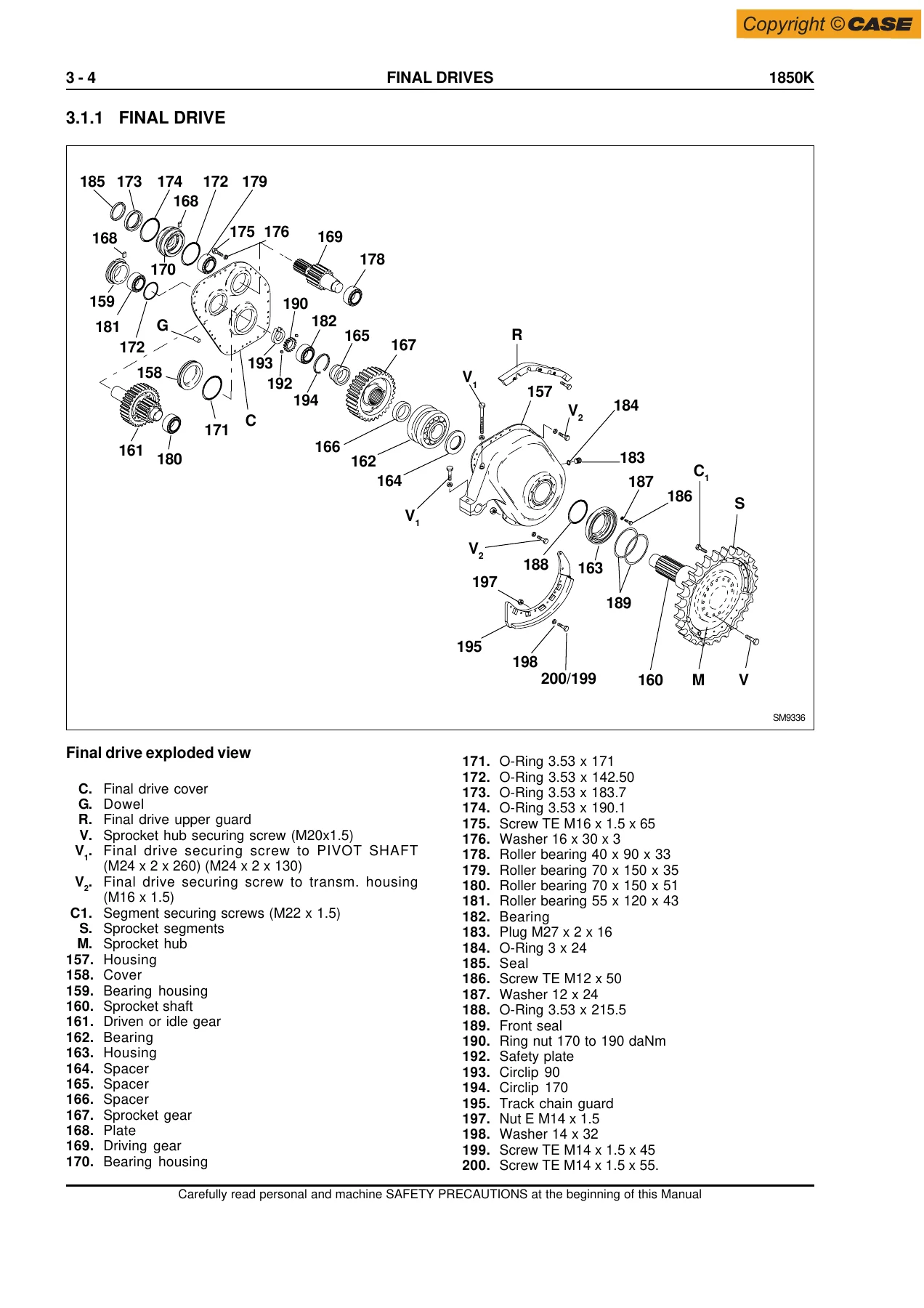
Final Drives
Double-reduction straight-spur final drives (1:12.286 ratio) — general description, exploded and sectional views, removal and disassembly from the transmission housing, pulling the housing cover, bearing removal from the driven and driving gear shafts, installation of the long-life front seals, and complete assembly procedures. Bearing installation interference values are given for every shaft and housing fit, along with the ring nut torque of 170 to 190 daNm and the required axial play checks.
Brakes and Steering
Brakes hydraulic diagram, brake circuit main components (powering pump, powering valve block, brake pedal valve, oil filters), steering circuit main components (hydraulic motor, transmission control lever), troubleshooting via the display with trouble codes, circuit pressure tests and diagnostic hose positioning, brake pedal adjustment, brake powering valve block setting, brake pedal valve removal/disassembly, brake power pump, the full brakes and steering differential procedure (removal, ring gear, planet carrier, sun gear, brake assembly overhaul, brake pack inspection), bevel gear set removal and re-assembly, procedures for setting the bevel pinion bearing pre-load and the bevel gear crown, and the housing cover re-installation and steering/equipment pump pressure check.
Undercarriage
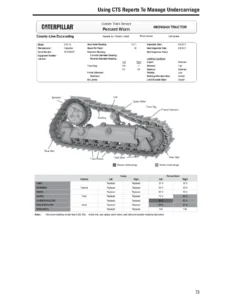
Track frame and component description, troubleshooting table, track chain inspection and adjustment, track tensioner pressure relief valve setting, track chain removal and installation, damaged link replacement, idler removal/reinstallation/overhaul, track chain tensioner spring removal, track chain support roller and bottom roller removal/installation/overhaul, and the specification sections for idler, sprockets, track chains, bottom rollers, support rollers, track tensioner device, front cross-member pivots and pivot shafts, plus a complete wear limit table with measuring procedures.
Dozing Equipment Hydraulic System
Operation of the load-sensing hydraulic system, blade and ripper control lever positions, equipment hydraulic schematic (PAT configuration), EST and BB3 diagnostic tool usage, joystick blade and ripper error codes, procedure for the dual setting relief valve, hydraulic oil reservoir removal, equipment hydraulic pump, hydraulic control valve removal/disassembly/overhaul (with individual electrovalves, safety valves, pressure compensators and flow limiting valves), blade removal and installation, blade adjustment, PD 180 ripper removal and installation for LT/XLT, RP 14F ripper removal and installation for LGP, and the full specifications and data section covering the electro/hydraulic control valve, hydraulic power pump, cylinders, push arms, rods, thrust arch, PAT blade and blade angle and tilt cylinders.
Electrical System
Electrical diagram of the protection tree, fuse layout (boxes A and B, link fuses, cold starting fuse), main switch, engine starting switch, back-up alarm, starter motor, alternator, manual accelerator control potentiometer, washer tank motors, cab wiper motors, implement/drivetrain safety levers, instrument panel and monitor operation with its electrical diagram, monitor senders, display diagnostics with trouble code tables, buzzer, relays/diodes/fuses, the 19/21/23-way main connectors, and the blade control pilot valve wiring.
Air Conditioning Unit
Operating principle of the R134a air conditioning system, heater and conditioner technical data, cab climate conditioner controls, service precautions, tool connections, discharging, refrigerant charging, leak inspection, and the complete troubleshooting chart including gauge pressure diagnosis for insufficient refrigerant, excessive refrigerant, air in the system, defective expansion valve, insufficient compressor compression, moisture infiltration and blocked refrigerant circulation.
What You Can Do With This Manual
The Case 1850K Tier 3 Crawler Dozer Service Manual covers the jobs that keep this machine on site: engine and converter removal, transmission clutch overhaul, final drive bearing replacement and seal installation, brake pack inspection with the 36.5 to 38.5 mm pack thickness tolerance, undercarriage wear measurement, track chain tension adjustment, ripper and blade removal, hydraulic valve overhaul, electrical fault tracing with the display trouble codes, and air conditioning charging and leak diagnosis. Every procedure is backed by the specific torques, pressures, clearances and special tool part numbers you need to do the job correctly — no guesswork, no generic advice.
Why Correct Service Information Matters
These are not consumer machines. A final drive ring nut torqued to the wrong value, a bevel pinion bearing pre-load set outside 0.2 to 0.4 daNm, or a brake pack assembled to the wrong thickness will fail in service — often catastrophically. This manual gives you the exact numbers Case specifies: converter safety valve at 10.5 ± 0.5 bar, transmission pressure at 16.5 to 17.5 bar, track tensioner relief valve at 900 to 950 bar, blade lift cylinder front sleeve at 114 to 126 daNm. Working from the manufacturer’s own figures is the difference between a repair that lasts and a comeback.
IMAGES PREVIEW
Instant PDF Delivery
This 1850K Tier 3 service manual is delivered as a PDF download immediately after payment — no shipping, no waiting, no physical book to lose. Read it on a laptop in the workshop, on a tablet next to the machine, or print the pages you need for the job and keep the rest clean. The 468-page PDF is fully portable and works on any device with a PDF reader.
Reviews
There are no reviews yet.