
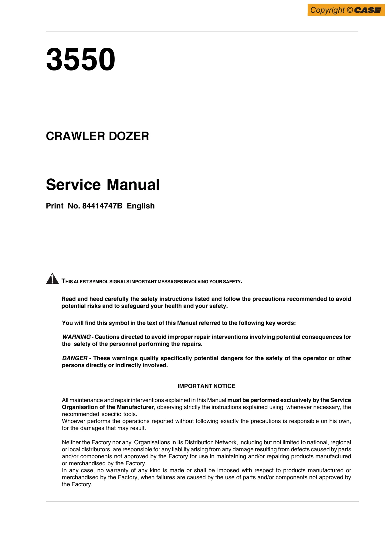
Case 3550 Crawler Dozer Service Manual – Complete Workshop Repair PDF (Print No. 84414747B)
Original price was: $59.95.$39.95Current price is: $39.95.
The complete Case 3550 Crawler Dozer Service Manual in PDF – 354 pages covering the Cummins QSM11 engine, TM400 power shift transmission, final drives, brakes and steering differential, undercarriage, dozing hydraulics and 24V electrical system. Print No. 84414747B.
Description
Case 3550 Crawler Dozer Service Manual – The Complete Workshop Reference
The Case 3550 Crawler Dozer Service Manual is the full workshop reference for this heavy crawler dozer, published under Print No. 84414747B. Across 354 pages it covers the Cummins QSM11 diesel engine, the TM400 power shift transmission and torque converter, the double-reduction final drives, the brakes and steering differential assembly, the undercarriage, the load-sensing dozing equipment hydraulics and the 24-volt electrical system. Every section is written for the working technician: step-by-step disassembly and reassembly, inspection criteria, service limits, adjustment procedures, hydraulic and electrical diagrams, and the torque, pressure and clearance values that decide whether a repair holds up in the field.
File Details
- Manual Type: Service Manual
- Brand: Case
- Model: 3550 Crawler Dozer
- Language: English
- Page Count: 354
- File Format: PDF
- Document Number: 84414747B
- Edition / Date: XII – 2011 (December 2011)
- Publisher: CNH Italia S.p.A. – Product Support
Machine and Engine Identification
Identification data in the manual covers three separate plates. The engine data plate is visible through the left side panel of the engine compartment and carries the Cummins Engine Serial Number (E.S.N.), the Control Parts List (CPL) and the engine model. The machine identification plate sits under the operator’s seat and shows the model and Product Identification Number. The frame marking is stamped on the left side of the transmission housing and follows the format FNH – 3550 – N – B – H – C – #####, decoding manufacturer code, machine code, check letter, year of production, manufacturing plant, product line and the last five serial digits. Engines in this manual are the Cummins QSM11 series, and the QSM11 nomenclature itself is broken down in Section 1 (model description, total displacement in litres, market application, and power at dynamometer brake).
Chapters Covered
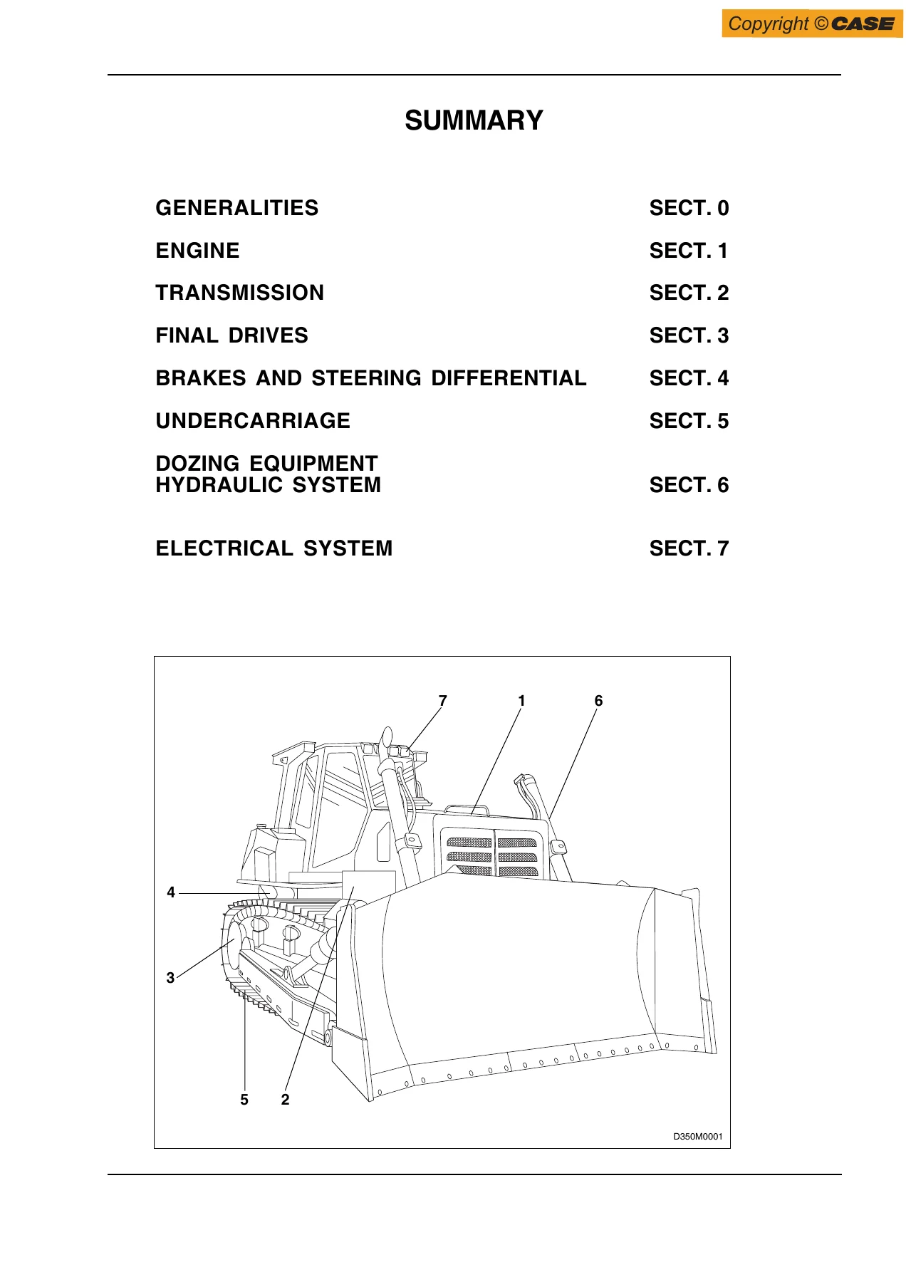
- Section 0 – Generalities
- Section 1 – Engine
- Section 2 – Transmission
- Section 3 – Final Drives
- Section 4 – Brakes and Steering Differential
- Section 5 – Undercarriage
- Section 6 – Dozing Equipment Hydraulic System
- Section 7 – Electrical System
Section 0 – Generalities
The foundation section for the whole manual. It opens with identification data, then the table of technical data, the table of capacities (cooling system, fuel tank, engine, torque converter-transmission, steering/brakes transmission housing, hydraulic system, final drives and grease fittings with their AKCELA fluid and lubricant specifications), main dimensions, and the 3550 specifications. Also here are the control data on the machine, the list of weights for the main service components (from the Cummins QSM11 engine at 1160 kg to individual thrust bearings and thrust washers), stability and centre-of-gravity data in transportation condition, general instructions for installing seals for rotating shafts and O-rings, cleaning and disassembly recommendations, high-pressure pipe and hose routing rules, the O-ring material compatibility chart (NBR, FKM/Viton, EPDM, MVQ), the troubleshooting methodology, the units of measure conversion tables, and the master table of tightening torques covering standard nuts and screws by diameter, pitch and strength class.
Section 1 – Engine
Full coverage of the Cummins QSM11-C diesel as installed in the 3550. General specifications, Series QSM 11 engine data (bore 125 mm, stroke 147 mm, total displacement 10.8 litres, firing order 1-5-3-6-2-4, valve clearances, oil and coolant capacities, thermostat opening, intake and exhaust restrictions, fuel system pressures), component diagrams viewed from the injection pump side, rear, front and turbocharger side, engine mounting on the frame with the tightening torques, the Cummins QSM11 diagnostics procedure through the ECM including the error code listing, the fan aftercooler control system with its sequence valve and counter pressure valve diagram, and the electronic throttle linkage with the potentiometer control lever and decelerator pedal.
Section 2 – Transmission
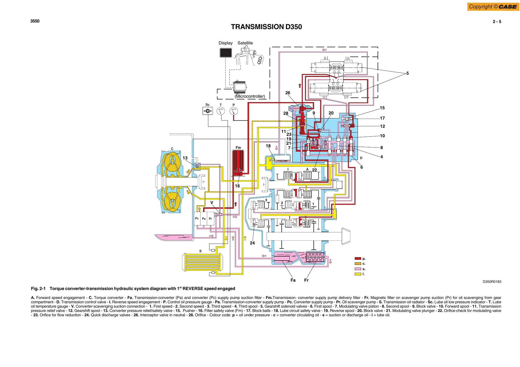
The torque converter and the TM400 power shift transmission. It begins with the operation of the converter-transmission hydraulic system – supply and scavenging, converter circuit, cooling, lubrication and flushing, gearshifting from 1st to 3rd forward and reverse, engagement of speeds, and the quick discharge valves. Removal and disassembly of the torque converter, inspection of parts and reassembly, the torque converter-transmission propeller shaft, transmission removal, clutch disassembly, inspection criteria for discs and springs, transmission reassembly, the transmission lubrication oil pressure relief valve, the converter-transmission-converter oil scavenger hydraulic pump overhaul, the transmission control valve removal, disassembly, inspection, reassembly and bench hydraulic tests, gearshift control including the safety lever, the transmission oil radiator, and the full troubleshooting section with a troubles-causes-remedies table plus on-machine tests for gearshifting and converter stalling, transmission-converter pressures, pump delivery and torque converter safety valve setting. Specifications, data, tightening torques and special tools close the section.
Section 3 – Final Drives
The double-reduction final drives – a straight-tooth single reduction plus an epicyclic planetary train, with a final ratio of 1:15.6. The section covers the general description with the section view and list of parts, removal and installation, disassembly, the installation procedure for the long-life front seals, and assembly. The specifications and data give the bearing mounting interference and clearance figures for each bearing seat (dimensions A through N), and the special tools list covers the seal mounting tools, punchers for the roller bearing outer races, the fitter for the driven wheel, and the caliper for checking washer play on the gear carrier.
Section 4 – Brakes and Steering Differential
The hydraulic braking system and the hydraulic steering system, treated in one section because they share the rear housing. Covered components include the brake/fan-drive pump, the brake feed valve block, the brake pedal valve, the brake oil suction and delivery filters, the hydraulic steering motor, and the steering pilot valve block with its ports. The failure diagnosis chapter works through the display, with single-component failure codes and multi-component code tables. Checks and adjustments cover hydraulic pressures, brake pedal adjustment, brake feed valve block setting, and steering lever setting with and without the BB3 instrument. The repair procedures are extensive: brake pedal valve removal and disassembly, brake hydraulic pump removal and reassembly, the brakes and steering differential removal, ring gear, planetary carrier and twin sun gear disassembly, brake assembly, planetary reassembly, ring gear reassembly and installation, brake discs pack check and inspection, support assemblies removal, disassembly, reassembly and installation, steering pinion bearing preload adjustment, steering bevel gear adjustment, bevel gear removal and reassembly, and the procedures for bevel gear adjustment and bevel pinion bearing preload.
Section 5 – Undercarriage
The complete undercarriage. General description explains the effect of terrain, gradient and material on wear rates. Main components cover the sector type sprocket, track frame bottom rollers, track chain support rollers, track chains, track frames, track tensioner device and idler. Troubleshooting lists the consequences of slack tension, high tension, insufficient tightening of shoe screws and working on steep slopes. Inspections cover track chain adjustment with the sag measurement, tensioning and loosening procedures. Repair procedures include track chain removal and installation with the master link torque sequence, replacement of a damaged link and reinstallation, idler removal, installation and overhaul including the tensioner spring removal, support roller removal and installation, and bottom roller removal and installation. Specifications and data give full dimensions and tightening torques for the idler, sprockets, track chains, bottom rollers, support rollers, track tensioner device and front linkage pivots, plus a dedicated wear limits table with nominal dimensions and replacement limits for pitch, link height, roller diameters, bushes, idler and sprocket.
Section 6 – Dozing Equipment Hydraulic System
The load-sensing dozing equipment hydraulic circuit. Operation of the system explains the variable displacement piston power pump, the separate steering and equipment circuits sharing pump and control valve, the pilot valves for blade and ripper control, the safety levers, the quick drop valves, the stroke-end valves in the blade cylinders, blade hydraulic tilt, blade control lever positions and ripper control lever positions. The full equipment hydraulic diagram is reproduced along with the reference performance table of pressures. Flow tests for single circuits are described. Repair procedures cover the hydraulic oil reservoir, the equipment hydraulic pump, the hydraulic control valve overhaul, and blade installation. Specifications and data cover the hydraulic control valve, hydraulic power pump, blade cylinder support fork, blade lifting control cylinder, blade tilt control cylinder for both Bulldozer and Angledozer versions, ripper lift cylinder, ripper pitch cylinder, push arms and blade rods, C-frame and rods, and the single shank ripper, plus a dedicated tightening torque table.
Section 7 – Electrical System
The 24-volt electrical system. Safety rules come first, then the protection tree wiring diagram, the fuse layout for both fuse holder boxes, the link fuses and cold starting fuse, the main switch, the engine starting switch, the back-up alarm and the starter motor. The instrument panel/monitor operation is documented with its reference table of indicator lights, alarm signals and connector ways, followed by the electrical diagram of the instrument panel and the monitor sender locations and settings (air cleaner clogging sensor, engine coolant max temperature switch, engine rpm sensor, engine oil low pressure sensor, alternator, fuel level sensor, hydraulic oil filter clogging sensor, brakes and steering clutches oil low pressure sensor, transmission oil low pressure sensor, transmission oil temperature sensor). Display diagnostics with the failure code tables, the buzzer, the relay group with diode boxes, diverter box and power relay, and the main connector pinout tables for the machine cable, extension cable, cab wiring and engine controller close the section.
What This 3550 Service Manual Lets You Do
With this Case 3550 service manual in hand, a technician can handle the full working range of repairs and diagnoses on the machine. On the engine side that means reading and interpreting Cummins QSM11 error codes, working through the ECM diagnostics, and servicing the fan aftercooler control system. On the drivetrain side it means overhauling the torque converter, rebuilding the TM400 power shift transmission with correct clutch pack thicknesses and piston strokes, and setting the transmission control valve on the bench. On the chassis side it means removing and rebuilding the final drives with the correct bearing preload, rebuilding the brakes and steering differential including the bevel gear and pinion, and setting the steering bevel gear backlash and pinion bearing preload to specification. On the undercarriage side it means measuring and adjusting track chain tension, replacing a damaged link, overhauling an idler, and judging component wear against the manual’s wear limits table. On the hydraulics side it means testing and setting the dozing equipment circuit pressures, servicing cylinders and control valve, and tracing a blade or ripper fault. On the electrical side it means reading the protection tree, checking fuse and relay logic, and following the connector pinouts to isolate a circuit fault.
The values matter. The 3550 service manual supplies the tightening torques, the hydraulic pressures, the bearing mounting interference figures, the clutch pack thicknesses, the brake disc wear limits, the track chain sag, and the electrical sender settings – the specific numbers that a repair either meets or fails. For anyone running a 3550 crawler dozer, whether as an owner-operator keeping a single machine alive or as a shop supporting a fleet, this is the reference that turns guesswork into a procedure.
IMAGES PREVIEW
The Case 3550 Crawler Dozer Service Manual is delivered as an instant PDF download. Nothing ships, nothing waits. Open it on a laptop in the workshop, a tablet on the machine, or a phone in the field, and print the pages you need for the job at hand. One download, the complete 3550 workshop reference at your fingertips.

Reviews
There are no reviews yet.