
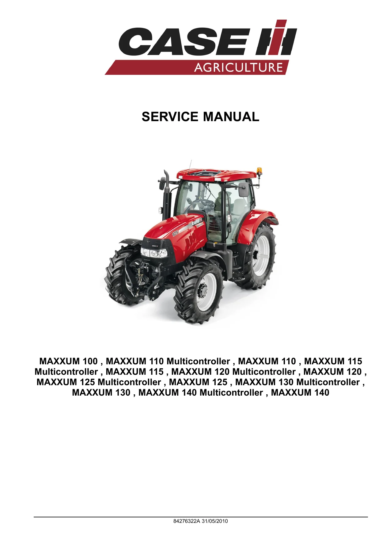
Case IH Maxxum 100 110 115 120 125 130 140 Tractor Service Manual 2010
Original price was: $44.95.$27.95Current price is: $27.95.
Comprehensive Case IH Maxxum service manual covering 100, 110, 115, 120, 125, 130 and 140 models including Multicontroller variants. Full hydraulic, electrical, electronic, engine, transmission, axle, brake and steering service procedures with specifications, diagnostics and fault codes.
Description
Case IH Maxxum 100 110 115 120 125 130 140 Tractor Service Manual 2010
This is the complete service manual for Case IH Maxxum tractors, covering models 100, 110, 115, 120, 125, 130 and 140, including all Multicontroller variants. Published under document number 84276322A dated 31/05/2010, this manual provides the full range of technical information needed for professional maintenance, repair and diagnostics on these machines. It spans every major system on the tractor — from the closed-centre load-sensing hydraulic circuits and electronic draft control, through the 12×12, 16×16 and 24×24 transmission options, to the engine management, electrical schematics and cab systems. The manual is written for technicians already familiar with agricultural machinery, and it follows the Case IH ICE coding system that organises information by location, information type and product.
File Details
- Manual type: Service Manual
- Brand: Case IH
- Models covered: Maxxum 100, 110, 115, 120, 125, 130, 140, including Multicontroller variants
- Document number: 84276322A
- Publication date: 31/05/2010
- Language: English
- Page count: 3970
- File format: PDF
- Systems covered: Hydraulic, Pneumatic, Electrical, Electronic, Engine, Transmission, Axles, Brakes, Steering, Cab, Hitch
- Diagnostic coverage: Fault code index, troubleshooting tables, electrical and hydraulic schematics
Chapters Covered
- Introduction — Foreword, Safety rules, Torque specifications, Consumables, Lubrications and Coolants, Capacities
- Section A — Hydraulic, Pneumatic, Electrical and Electronic Systems
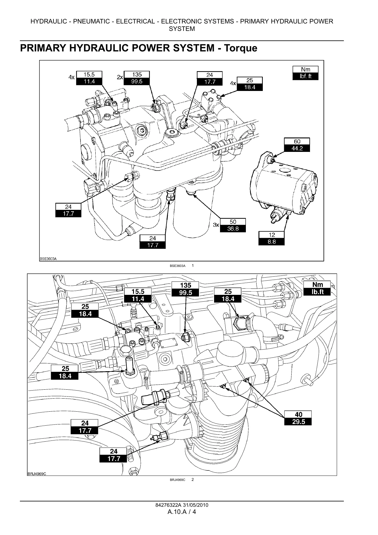
- A.10.A — Primary Hydraulic Power System
- A.10.B — Primary Hydraulic Power System: Closed centre mechanical remote valve
- A.10.C — Primary Hydraulic Power System: Electro-hydraulic remote valve
- A.10.D — Primary Hydraulic Power System: Open centre mechanical remote valve
- A.12.A — Secondary Hydraulic Power System
- A.14.A — Hydraulic Command System
- A.30.A — Electrical Power System
- A.50.A — Electronic System, Fault Codes
- Section B — Engine and PTO
- B.10.A — Engine
- B.20.A — Fuel and Injection System
- B.30.A — Air Intake System
- B.40.A — Exhaust System
- B.50.A — Engine Coolant System
- B.80.A — Starting System
- Section C — Transmission, Drive and PTO
- C.10 — Power Coupling Clutch
- C.20 — Transmission Mechanical, Power Shuttle, Semi-Powershift
- C.30 — Additional Reducers: Creeper, Overdrive
- C.40 — Rear PTO Hydraulic
- C.42 — Front PTO Hydraulic
- Section D — Axles, Brakes and Steering
- D.10.A — Front Axle
- D.12.A — Rear Axle
- D.14.C — 2WD-4WD System Hydraulic
- D.20.C — Steering Hydraulic
- D.30.C — Service Brake Hydraulic
- D.32.B — Parking Brake Mechanical
- D.34.C — Brake Connection Hydraulic
- D.40.C — Suspension Hydraulic
- D.50.C — Wheels and Tracks: Wheels
- Section E — Frame and Cab
- E.10.B — Frame: Primary frame
- E.20.A — Shield
- E.32.A — User Controls and Seat
- E.34.A — User Platform
- E.40.D — Environment Control: Heating, ventilation and air-conditioning
- Section H — Hitch and Working Tool
- H.10.B — Hitch: Front hitch
- H.10.C — Hitch: Rear hitch
- H.10.D — Hitch: Electronic draft control
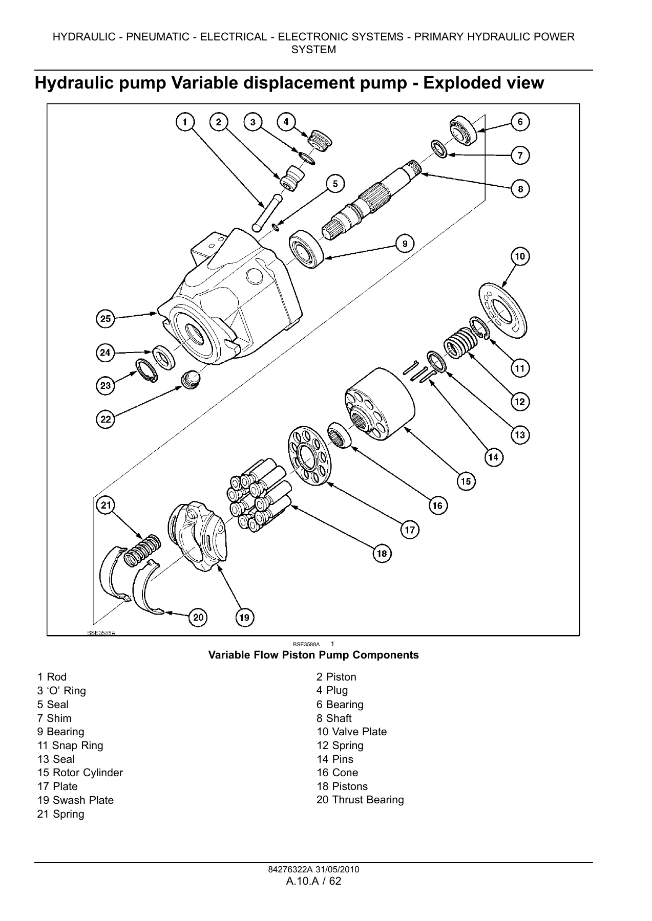
This Case IH Maxxum service manual is structured so a technician can move from general specifications down to component-level repair. Section A opens with the complete hydraulic architecture — the variable displacement pump and charge pump assembly, closed-centre load sensing, flow and pressure compensating valves, and all three remote valve configurations. It continues into the electrical power system with fuse and relay layouts, the CAN bus electrical schematics for every build configuration, and a full fault code index for the electronic control modules. Section B covers the engine as a complete unit, including the fuel and injection system, air intake, exhaust, coolant circuit, and starting system, with torque values and service data at the component level. Section C covers every transmission variant offered across the Maxxum range — 12×12, 16×16 and 24×24 — including clutch pack service, synchroniser repair, power shuttle and semi-powershift operation, creeper and overdrive reducers, and both rear and front PTO hydraulic circuits. Section D covers the driveline and running gear: front and rear axles, the 2WD-4WD engagement system, hydrostatic steering, service and parking brakes, trailer brake connections, front axle suspension, and wheel and track specifications. Section E covers the frame, cab structure, operator platform, seat, controls, and the complete heating, ventilation and air-conditioning system. Section H covers the front hitch, rear hitch and electronic draft control, with calibration procedures for the lift system. Throughout the manual, each system is documented through Technical Data (specifications), Functional Data (how it works), Diagnostic Data (fault codes and troubleshooting), and Service Data (remove, disassemble, assemble, install, adjust).
What This Manual Enables You To Do
With this manual you can perform complete mechanical, hydraulic and electrical repairs on any Maxxum 100 through 140 tractor without relying on guesswork. The hydraulic schematics and circuit diagrams let you trace oil flow through the closed-centre load-sensing system, diagnose pressure and flow faults with the specified test procedures, and rebuild the variable displacement piston pump, charge pump, flow and pressure compensators and remote valve stacks to the correct torque and clearance values. The electrical schematics cover every build configuration — 12×12, 16×16, 24×24, with and without cab, with and without Multicontroller — so wiring faults on the engine ECU, transmission controller, armrest control unit, instrument cluster, EHR valves, front axle suspension and auto-guidance system can be traced connector by connector. The fault code index and diagnostic tables give you the exact code meanings and test steps for the electronic control modules. The transmission chapter covers clutch pack disassembly and reassembly, synchroniser service, creeper and overdrive installation, and the hydraulic control circuits for power shuttle and semi-powershift. The engine chapter gives you injection system data, fuel filter and heater circuits, cooling system capacities, and starting system diagnostics. The axle, brake and steering chapters give you the specification values needed to rebuild the front axle, set the brakes, service the parking brake and repair the steering system. The hitch chapter gives you the calibration procedures for the electronic draft control valve and the front and rear hitch systems.
Why Correct Procedures and Specifications Matter
Modern agricultural tractors rely on tightly controlled hydraulic pressures, electronic calibration values and precise mechanical tolerances. A variable displacement pump set outside its specified pressure range will not deliver the correct oil flow to the remote valves and lift cylinder, causing slow or erratic operation. A transmission clutch pack assembled with the wrong clearance will slip or drag, leading to premature failure. An electronic draft control valve that has not been calibrated will not respond correctly to load changes, affecting implement control and soil engagement. The torque values, pressure settings, flow rates, clearance limits and calibration procedures in this manual are the values the tractor was designed to, and they are the values that keep it working reliably. Using the correct procedure also prevents damage to adjacent components — for example, removing a hydraulic pump without supporting it correctly, or disconnecting the battery without following the correct sequence, can cause damage that is far more expensive than the original repair.
Delivery
IMAGES PREVIEW
The manual is delivered as an instant PDF download after purchase. There is no shipping, no waiting for a physical book, and no import charges. The file can be stored on any computer, tablet or smartphone, opened in any standard PDF reader, and printed if a paper copy is needed in the workshop. All 3970 pages are included in a single file, with the contents and index structured so you can navigate directly to the system or procedure you need.

Reviews
There are no reviews yet.