
Caterpillar 6040 Hydraulic Shovel Parts Manual EM030763-0 March 2021
Original price was: $34.95.$19.95Current price is: $19.95.
Parts catalog for the Caterpillar 6040 hydraulic shovel powered by the CAT C32 engine. Publication EM030763-0 (en-us), March 2021, with group names, consist quantities, serial captions, and exploded-view graphics for S/N 40203-40203.
Description
File Details
| Manual Type: | Parts Manual |
| Brand / Model: | Caterpillar 6040 Hydraulic Shovel |
| Language: | English (en-us) |
| Page Count: | 1088 |
| File Format: | |
| Publication Number: | EM030763-0 |
| Date: | March 2021 |
| Cover Arrangement: | DHJ40203 |
| Engine Shown on Cover: | CAT C32 |
What This Catalog Is For
The Caterpillar 6040 Hydraulic Shovel Parts Manual EM030763-0 March 2021 is a parts-identification book for one mining-class hydraulic shovel. It is not a service or operation manual. Every information element opens with a caption that lists the group part number, the group name, and the serial-number band that applies, most often S/N: 40203-40203 and, on many shared components, S/N: 402-402. Those captions are the filter a parts person uses before pulling a line item from the consist list.
A product-and-dealer sheet at the front leaves blanks for delivery date, product identification number, engine serial number, transmission serial number, generator serial number, attachment serial numbers, and dealer contacts. The foreword then explains how Cat machines are identified by PIN, how component serial numbers differ from the machine PIN, and why every order should include quantity, part number, part name, and the machine identification numbers. A warning on that same page states that replacement parts should match physical dimensions, type, strength, and material, and that failure to follow that guidance can lead to premature failures, product damage, personal injury, or death.
How the Pages Are Built
Information elements are arranged alphabetically by part name inside each major section, then by part number. Captions in large type mark the start of a new group. Continuation pages carry the word (contd.). Non-serviced numbers that only exist to point down to a lower-level consist appear in italic type and are not sold as standalone items. Reference numbers in the consist table match callouts on the associated graphic. A Graphic Ref column ties a line item to a specific illustration when a group spans more than one drawing. The symbol <END> closes an element. A part-number index occupying the B-section at the back points back to the printed page where that number first appears as a primary reference.
Several high-value groups carry an explicit reman note in the caption itself: stick, boom, and bucket cylinder groups; piston motor and double pump groups; swing drive; and final drive. Those notes sit next to the serviceable consist so a planner can choose a new assembly or the reman option listed on the same page.
Chapters Covered
- Foreword and Index
- Air Inlet and Exhaust System — Filter As-Air, Precleaner As, Cleaner Gp-Air-B
- Air Cleaner Gp — Filter System
- Exhaust Gp — Install Material Left, Install Material Right, Intake/Exh. System
- Inlet Gp-Air — Intake System Left and Right
- Cooling System — Cooler, Reservoir, Cooling Gp, Water Installation
- Electrical and Starting System — Plug As, Motor Gp-Electric, Wire As-Starter, Switch, Sensor, Instl Gp-Field, Drive As-Motor, Holder As-Brush, Armature As
- Battery Gp and Camera Gp
- Engine Arrangement — Atomizer Gp, Engine Ar, Installation Ar, Engine Mounting
- Frame and Body — Frame As-End, Plate As-Brush, Brackets, Covers, Ladder Gp, Bearing As, Frame As-Track, Gear Gp-Brg, Support Gp-Frame, Guards, Lifting Gp, Lines Gp-Drain, Shaft As, Mounting Gp, Stick Gp-Shovel, Plate As-RH / Plate As-LH
- Ballast Gp, Catwalk Gp, Cover Gp, Frame Gp — Fuelling System Grease, Slewing Gear Complete, Upper Carriage with Mount Parts, Drive Gp-Swing
- Ladder Gp and Lubrication Gp — Greasing System, Greasing System BH Mono, Lube Pump, Greasing System BH Stick
- Panel Gp and Step Gp
- Fuel System — Filter As-Primary, Fuelling System Fuel
- Hydraulic System — adapters, elbows, plugs, nipples, solenoids, relief and control valves, rotating groups, shim kit, piston motor, stick / boom / bucket cylinder groups, gear pump, gear motor, double pump, piston pump, accumulators, filter-lube, swing drive, hydraulic filter, check valves, orifice gp-hyd, pump gp, lines gp-motor / pilot / drain / grease
- Block Gp — Control Block Driving, Control Block Monoblock Boom, Travel Control Block, Hydraulic System Monoblock Boom
- Brake Gp — Hydr. System Swing Brake
- Control Gp-Fan — Hydr. Fan Drive Ballast, Hydr. Syst.-Fandrive Engine Mod.
- Cooler Gp — Hydr. Oil Cooling, Fan Drive Oil Cooler Module, Gearbox Oil Cool modules
- Cylinder Gp, Filter Gp (HP Filter Right-Hand and Left-Hand), Hydraulic Gp, Motor Gp (Fan Motor), Mounting Gp, Propel Gp-Hydraulic, Pump Gp, Rotator Gp, Tank Gp, Valve groups (check and relief, control, pressure balance, servo)
- Implements — Clamp Gp-Lug, Clamp Gp-Lines, Shaft, Linkage, Linkage Gp-Bkt, Stick As, Boom Gp Monoblock Boom, Toggle/Linkage, Stick BH Mounting Parts, Pin No.1
- Lubrication System — Service Center Gp, Fuelling System Oil
- Machine Arrangement — Chassis Ar Upper Carriage, Machine Ar Assembly Parts, Options, Undercarriage Ar, Tools Attachment
- Operator Station — Air Conditioner Gp, Cab Gp, Control Column, Guard Grid, Mirror Gp, Platform Gp, Seat Gp, Washer Gp-Window, Window Gp, Wiper Gp-Window
- Pneumatic System — Compressor Gp
- Power Train — Drive Gp-Final, Gear-Planet, Planetary As, Brake Kit-Disc / Spring / Seal, Drive Gp-Final-C, Guard Gp-Sprkt, Clutch Gp Coupling/Clutch, Gearbox Gp Pump Gearbox
- Service Equipment and Supplies — Seal Gp-Duo Cone, Kits and Accessories, Charts and Films, Installation Parts-Vice, Maintenance Mater., Tool Set
- Undercarriage — Roller Gp-Single Flange, Idler Gp-Front, Idler As, Roller Gp, Rim As, Track Gp, Track As, Frame As-Track, Carbody As, Lines Gp-Tnsn, Roller Gp-Track, Cyl Gp-Mounting, Sprocket Gp-B, Seal Gp-Duo Cone, Carbody Ar, Frame Ar-Track, Track Ar
- Work Tools — Boom, Boom As
- Part Number Index
Taken together, those headings give a parts planner a map of the shovel from intake filters to track assemblies. The Caterpillar 6040 Hydraulic Shovel Parts Manual EM030763-0 March 2021 does not narrate how to remove a pump or set a relief valve. It does tell you which muffler, clamp, seal, piston, planet gear, or idler seal belongs in a given group and how many pieces that group uses.
Engine Module, Cooling, and Inlet Path
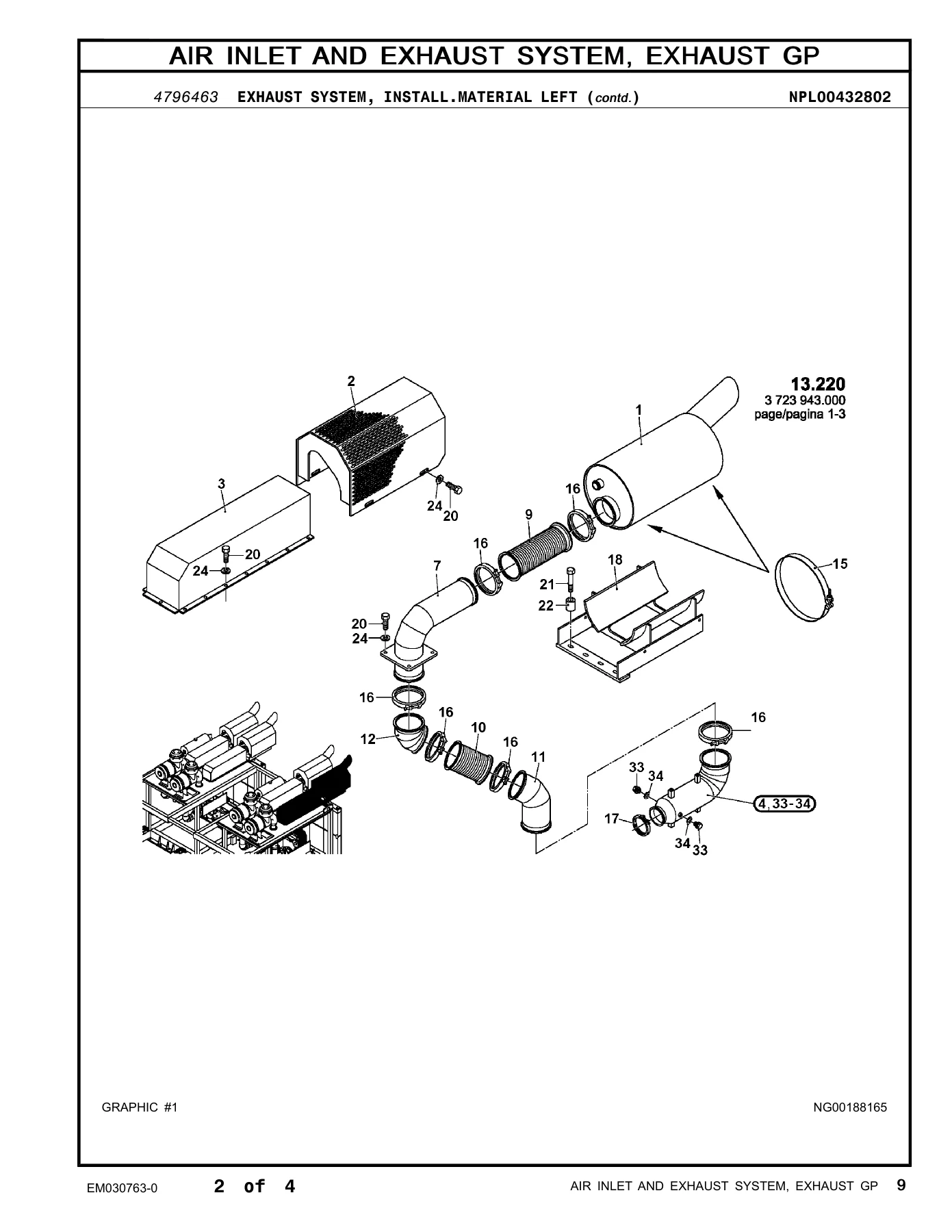
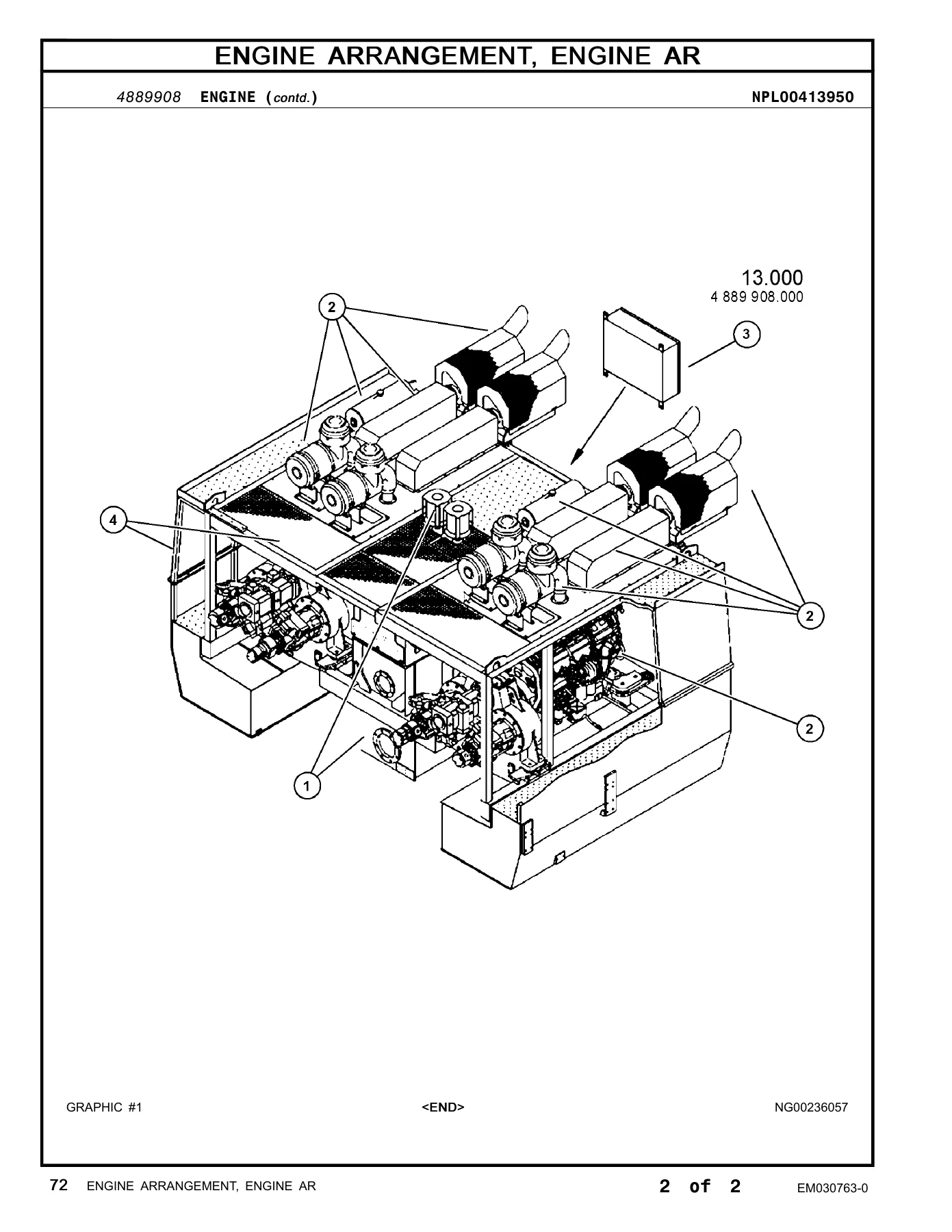
Cover wording states the machine is powered by a CAT C32 engine. Engine Arrangement pages then split the power module into atomizer group, engine arrangements 4889908 and 4890107, mounting group 4794453, and installation arrangements that tie the engine to the hydraulic oil tank mounting parts, battery installation material, and paneling. Cooling pages cover cooler 533-8330, reservoir 535-3009, the water fuelling group, and multi-page cooling-system installations. Air inlet and exhaust pages list primary and secondary filter elements inside 122-6616 Filter As-Air, precleaner 130-3281, cleaner group 254-3566, left- and right-hand exhaust installation material with mufflers, guards, elbows, V-band clamps, and insulation, plus matching left and right intake installation material.
Hydraulic Groups and Implement Iron
The hydraulic section is the largest block in the book. It begins with plugs, rotating groups, elbows, straight and tee adapters, a nipple, a piston assembly, solenoids, an ether valve, and a relief valve group, then moves into pump adapters, control valves, a shim kit that includes eight shims, pump valves, shafts, couplings, and the 437-0158 piston motor group with a reman option and optional service replacement 20R-2021. Stick cylinder 465-8688, boom cylinder 465-8707, and bucket cylinder 467-1554 each carry the same reman note. Gear pump, gear motor, double pump, slipper-type piston pump, accumulators, lube filter, and hydraulic accumulator groups follow, then swing drive 478-0706 with reman availability, hydraulic filters, check and control valve stacks, orifices, a basic piston pump, fuel tank assembly 548-0861 sitting inside the hydraulic pages, and multiple motor, pilot, drain, and grease line groups.
Block-group pages isolate the driving control block, the monoblock-boom control block, the travel control block, and the eleven-page monoblock-boom hydraulic system. Separate groups cover swing brake, ballast fan drive, engine-module fan drive, hydraulic oil cooler modules, gearbox oil cooler modules, right-hand and left-hand high-pressure filters, flushing valve, BH stick hydraulics, engine-module drive and leak-oil systems, upper-carriage hydraulics, slewing hydraulics, oil suction, fan motor, slewing and hydro-control mounting plates, travel control complete, fan pump, left and right pump installation material, rotor, hydraulic oil tank mounting parts, pressure-release and check valves, float valve, swing balance valve, and servo control.
Implement pages list lug and line clamps, bucket linkage groups, stick assemblies 559-3119 and 559-3120, monoblock boom 4927030, toggle/linkage, stick BH mounting parts, and Pin No.1. Work-tool pages at the end return to boom and boom assemblies 561-5937 and 561-5938.
Frame, Undercarriage, and Power Train
Frame and body coverage runs from end frames and brush plates through track frames, bearing assemblies, swing gear complete 4892447, upper carriage with mount parts 4898809 (including swing ring 4592047), swing drive 514-5276, ballast, catwalks, paneling, and steps. Lubrication groups document the central greasing system, monoblock and stick greasing circuits, the lube pump, and oil, grease, and fuel filling arrangements.
Power-train pages open with final drive 484-6333, again marked reman-available, then planet gears, planetary assemblies, disc / spring / seal brake kits, final-drive-C groups, sprocket guards, coupling/clutch and its installation material, and the pump gearbox with oil filling, installation material, and mounting parts. Undercarriage pages itemize the front idler group 465-8509 and idler assembly, single-flange and track rollers, rim, track group and track assembly, track frames, carbody assemblies, tension lines, mounting cylinders, idler mounting, installation group, track-frame arrangement, motor mounting, sprocket groups, and duo-cone seals, then close with carbody, track-frame, and track arrangements.
Cab, Electrical, and Service Items
Electrical and starting coverage includes the electric motor group, starter wire, switch, sensor, field installation, motor drive, brush holder, armature, battery installation material, and the camera group. Operator-station pages cover air conditioning and condenser groups, heated mirror, cab module and operator’s cab with installation material, control column, guard grid, mirrors and brackets, platform plate and joystick control assemblies, seat, washer system, roller blind, and windscreen wiper installation material. A compressor group sits under Pneumatic System. Service equipment pages add duo-cone seal groups, kits and accessories, plate and layout films, vice installation parts, maintenance material, and a multi-page tool set.
Using the Lists on a Live Machine
A typical lookup starts at the index or the table of contents, moves to the matching caption, confirms the S/N band, then reads the consist table against the exploded graphic. Graphic # callouts and NPL reference numbers printed in each header keep the list and the drawing aligned. Where a line points to another page in the See Page column, that lower-level group holds the next layer of serviceable pieces. The part-number index is the fast path when the only known data is a number stamped on a tag or written on a work order.
Because this is a parts book for a single published arrangement of the 6040, the correct use of the Caterpillar 6040 Hydraulic Shovel Parts Manual EM030763-0 March 2021 is to match the machine PIN and component serials to the captions before ordering. Groups that list both 402-402 and 40203-40203 apply across those printed bands; groups that list only 40203-40203 stay inside that caption.
Get the Manual and Identify the Right Pieces
With this file a parts planner or technician can build pick lists for air filters and exhaust hardware, cooling and fuel filling parts, engine-module mounting pieces, hydraulic pumps, motors, cylinders, valves, and lines, monoblock boom and stick iron, swing and travel drives, final drives and brake kits, track, idler, roller, and carbody components, cab and air-conditioning hardware, and the tool and film sets printed in the service section. Ordering from the printed consist instead of a guess keeps quantities, seals, and mating adapters aligned with the group that is actually on the shovel. After payment the PDF is delivered immediately. There is no shipment to wait on. Open it on a phone, tablet, or workshop computer and print the pages needed for a bench or a parts counter.
Reviews
There are no reviews yet.