Caterpillar EP16 EP18 EP20 EP25 EP30 Chassis with MicroCommand II™ Controller Service Manual
Original price was: $86.95.$29.95Current price is: $29.95.
Caterpillar EP16 EP18 EP20 EP25 EP30 Chassis with MicroCommand II™ Controller Service Manual – PDF DOWNLOAD
For 36/48V Trucks
EP16 & EP18 E1EP1-60001 & up
EP20 & EP25 E1EP2-60001 & up
EP30 E1EP3-60001 & up
For 72/80V Trucks
EP16 & EP18 E1EP1-80001 & up
EP20 & EP25 E1EP2-80001 & up
EP30 E1EP3-80001 & up
Description
Caterpillar EP16 EP18 EP20 EP25 EP30 Chassis with MicroCommand II™ Controller Service Manual – PDF DOWNLOAD
CATERPILLAR EP16 EP18 EP20 EP25 EP30 CHASSIS WITH MICROCOMMAND II™ CONTROLLER SERVICE MANUAL:
IMAGES PREVIEW OF THE MANUAL:


DESCRIPTION:
Caterpillar EP16 EP18 EP20 EP25 EP30 Chassis with MicroCommand II™ Controller Service Manual – PDF DOWNLOAD
For 36/48V Trucks
EP16 & EP18 E1EP1-60001 & up
EP20 & EP25 E1EP2-60001 & up
EP30 E1EP3-60001 & up
For 72/80V Trucks
EP16 & EP18 E1EP1-80001 & up
EP20 & EP25 E1EP2-80001 & up
EP30 E1EP3-80001 & up
Foreword:
This service manual has instructions and procedures for the subject on the front cover. The information, specifications, and illustrations used in this manual are based on information that was current at the time this issue was written. Correct servicing will give these lift trucks a long, productive life.
- Before attempting to start a test, repair or rebuild job, be sure you have studied the respective sections of this manual, and know all the components you will work on.
- Safety is not only your concern but everybody’s concern. Safe working habits cannot be bought or manufactured; they must be learned through the job you do.
- By learning what CAUTION or WARNING symbol emphasizes, know what is safe — what is not safe. Consult your foreman, if necessary, for specific instructions on a job, and the safety equipment required.
The service mechanic may be unfamiliar with many of the systems on this machine. This makes it important to use caution when performing service work. A knowledge of the system and/or components is important before the removal or disassembly of any component. Because of the size of some of the machine components, the service mechanic should check the weights noted in this manual. Use proper lifting procedures when removing any components. Following is a list of basic precautions that should always be observed.
TABLE OF CONTENTS:
Caterpillar EP16 EP18 EP20 EP25 EP30 Chassis with MicroCommand II™ Controller Service Manual – PDF DOWNLOAD
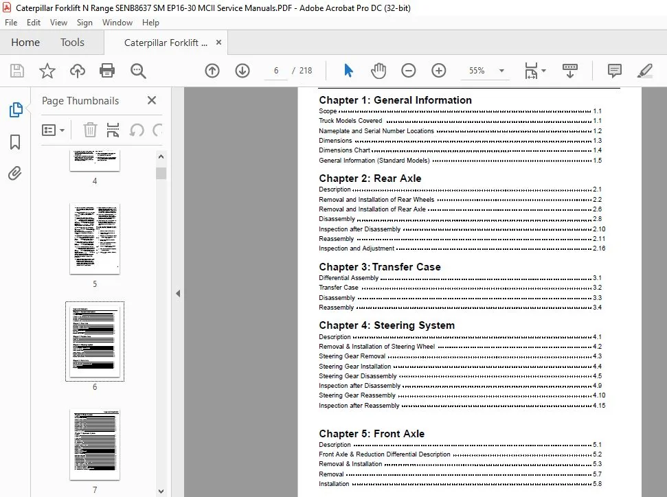
Chapter 1: General Information
Scope 1.1
Truck Models Covered 1.1
Nameplate and Serial Number Locations 1.2
Dimensions 1.3
Dimensions Chart 1.4
General Information (Standard Models) 1.5
Chapter 2: Rear Axle
Description 2.1
Removal and Installation of Rear Wheels 2.2
Removal and Installation of Rear Axle 2.6
Disassembly 2.8
Inspection after Disassembly 2.10
Reassembly 2.11
Inspection and Adjustment 2.16
Chapter 3: Transfer Case
Differential Assembly 3.1
Transfer Case 3.2
Disassembly 3.3
Reassembly 3.4
Chapter 4: Steering System
Description 4.1
Removal & Installation of Steering Wheel 4.2
Steering Gear Removal 4.3
Steering Gear Installation 4.4
Steering Gear Disassembly 4.5
Inspection after Disassembly 4.9
Steering Gear Reassembly 4.10
Inspection after Reassembly 4.15
Chapter 5: Front Axle
Description 5.1
Front Axle & Reduction Differential Description 5.2
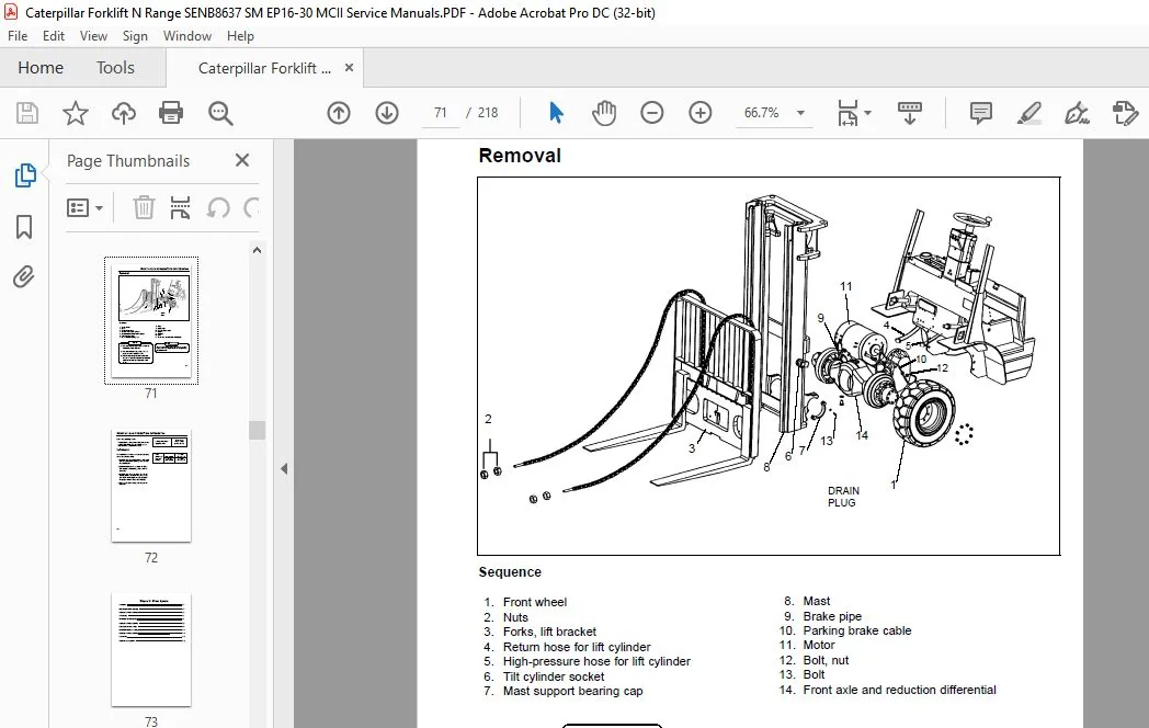
Removal & Installation 5.3
Removal 5.7
Installation 5.8
TABLE OF CONTENTS
Chapter 6: Brake System
Description 6.1
Master Cylinder Disassembly 6.2
Inspection after Disassembly 6.3
Reassembly 6.3
Wheel Brakes Disassembly 6.4
Inspection after Disassembly 6.6
Brake System Reassembly 6.8
Wheel Cylinder Disassembly 6.11
Inspection after Disassembly 6.12
Reassembly 6.12
Inspection & Adjustment 6.13
Chapter 7: Hydraulic System
Description 7.1
Hydraulic Tank 7.2
Hydraulic Pump 7.3
Control Valve 7.5
Tilt & Lift Cylinder 7.6
Flow Regulator Valve 7.7
Down Safety Valve 7.8
Removal & Installation Warning 7.9
Pump Removal 7.10
Pump Installation 7.11
Pump Disassembly 7.12
Inspection after Disassembly 7.16
Pump Reassembly 7.18
Inspection after Assembly 7.24
Priority Valve Disassembly 7.25
Priority Valve Reassembly 7.28
Control Valve Removal 7.32
Control Valve Installation 7.33
Control Valve Disassembly 7.34
Control Valve Inspection and Reassembly 7.36
Hydraulic System Disassembly 7.37
Hydraulic System Installation 7.39
Tilt & Lift Cylinder Disassembly 7.41
Tilt & Lift Cylinder Inspection after Disassembly 7.43
Flow Regulator Valve Disassembly 7.44
TABLE OF CONTENTS
TABLE OF CONTENTS
Hydraulic System Inspection & Adjustment 7.45
Control Valve Inspection & Adjustment 7.46
Tilt & Lift Cylinder Inspection & Adjustment 7.48
Adjustment Method 7.49
Testing 7.50
Chapter 8: Mast and Forks
Description 8.1
Removal & Installation 8.3
Disassembly 8.6
Inspection after Disassembly 8.8
Reassembly 8.9
Inspection and Adjustment 8.10
Chain Tension Adjustment 8.11
Lift Bracket Adjustment 8.12
Mast Clearance Adjustment 8.14
Mast Adjustment Chart 8.20
Chapter 9: Troubleshooting
Front Axle & Reduction Differential 9.1
Brake System 9.2
Steering System 9.4
Hydraulic System 9.6
Rear Axle 9.8
Mast & Forks 9.9
Chapter 10: Maintenance Service Data
System Service Charts
Front Axle and Reduction Differential 10.1
Transfer Case 10.3
Rear Axle 10.4
Brake System 10.6
Steering System 10.10
Hydraulic System 10.12
Mast and Forks (Simplex Mast) 10.15
Tightening Torques for Standard Bolts and Nuts
Fine Thread—With Spring Washer 10.17
Fine Thread—Without Spring Washer 10.18
TABLE OF CONTENTS
Coarse Thread—With Spring Washer 10.19
Coarse Thread—Without Spring Washer 10.20
Maintenance Chart 10.21
Periodic Replacement Parts 10.26
Lubrication Data 10.27
Chart 10.27
Fuel and Lubricant Specifications 10.28
Recommended Brands of Lubricants 10.29
Weight of Major Components (Approximate) 10.30
Special Service Tools 10.31
Special Tool Illustrations 10.32
Inspection Guide 10.35
PLEASE NOTE:
- This is the SAME exact manual used by your dealers to fix your vehicle.
- The same can be yours in the next 2-3 mins as you will be directed to the download page immediately after paying for the manual.
- Any queries / doubts regarding your purchase, please feel free to contact [email protected]
S.V