Trusted Business
Verified & Licensed
Virus Free Files
100% Safe Downloads
Secure Payment
SSL Protected
Instant Delivery
Available Immediately
Sale!


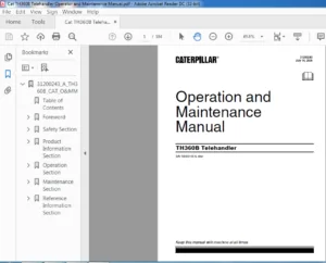
CATERPILLAR TH414 TH514 TH417 Parts Manual – PDF DOWNLOAD 
CATERPILLAR TH414 TH514 TH417 Parts Manual – PDF DOWNLOAD
CATERPILLAR TH414 TH514 TH417 Parts Manual – PDF DOWNLOAD
Original price was: $80.00.$16.95Current price is: $16.95.
CATERPILLAR TH414 TH514 TH417 Parts Manual – PDF DOWNLOAD
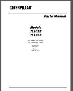
S/N TBZ00100 & After
S/N TBW00100 & After
S/N TBT00100 & After
31200488
Instant PDF Download
Available immediately
Save to Your Device
Download & keep forever
Antivirus Scanned
100% virus-free
Trusted Worldwide
175,000+ customers
Description
CATERPILLAR TH414 TH514 TH417 Parts Manual – PDF DOWNLOAD
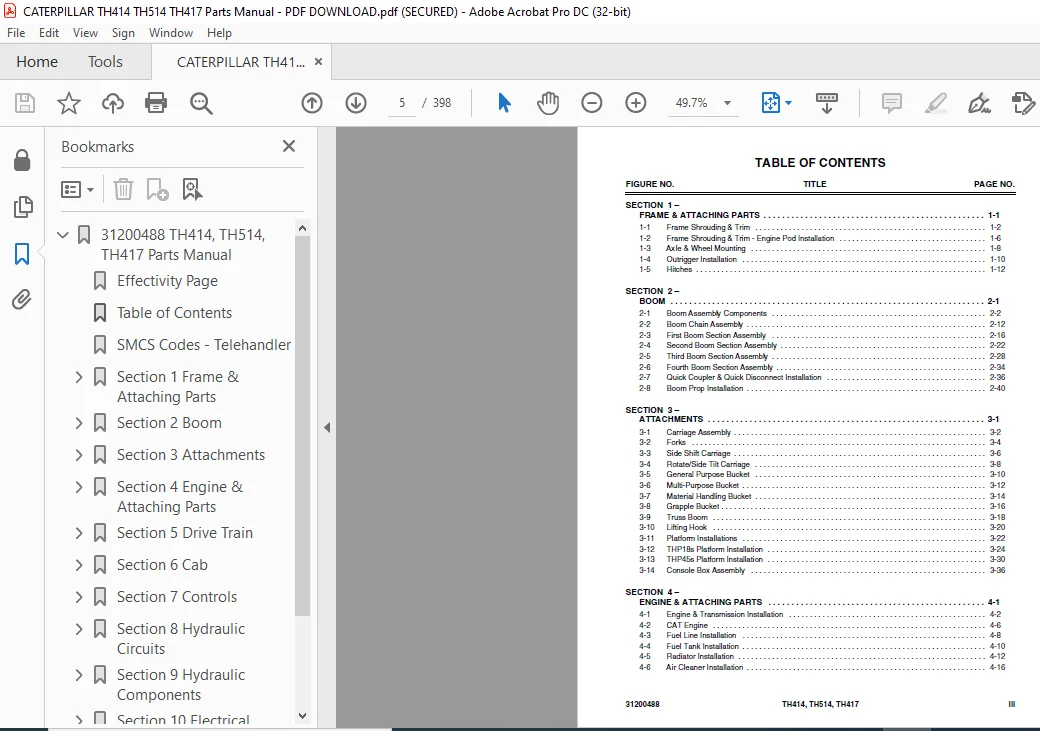
TABLE OF CONTENTS:
CATERPILLAR TH414 TH514 TH417 Parts Manual – PDF DOWNLOAD
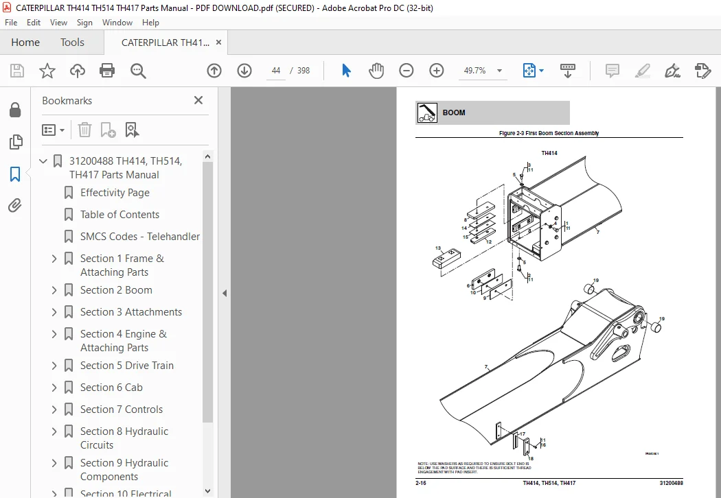
31200488 TH414, TH514, TH417 Parts Manual.......................................  1
	Effectivity Page
...........................................................  3
	Table of Contents
..........................................................  5
	SMCS Codes - Telehandler....................................................  9
	Section 1 Frame & Attaching Parts........................................... 15
		Figure 1-1 Frame Shrouding & Trim....................................... 16
		Figure 1-2 Frame Shrouding & Trim - Engine Pod Installation............. 20
		Figure 1-3 Axle & Wheel Mounting........................................ 22
		Figure 1-4 Outrigger Installation....................................... 24
		Figure 1-5 Hitches...................................................... 26
	Section 2 Boom.............................................................. 29
		Figure 2-1 Boom Assembly Components..................................... 30
		Figure 2-2 Boom Chain Assembly.......................................... 40
		Figure 2-3 First Boom Section Assembly.................................. 44
		Figure 2-4 Second Boom Section Assembly................................. 50
		Figure 2-5 Third Boom Section Assembly.................................. 56
		Figure 2-6 Fourth Boom Section Assembly................................. 62
		Figure 2-7 Quick Coupler & Quick Disconnect Installation................ 64
		Figure 2-8 Boom Prop Installation....................................... 68
	Section 3 Attachments....................................................... 71
		Figure 3-1 Carriage Assembly............................................ 72
		Figure 3-2 Forks........................................................ 74
		Figure 3-3 Side Shift Carriage.......................................... 76
		Figure 3-4 Rotate/Side Tilt Carriage.................................... 78
		Figure 3-5 General Purpose Bucket....................................... 80
		Figure 3-6 Multi-Purpose Bucket......................................... 82
		Figure 3-7 Material Handling Bucket..................................... 84
		Figure 3-8 Grapple Bucket............................................... 86
		Figure 3-9 Truss Boom................................................... 88
		Figure 3-10 Lifting Hook................................................ 90
		Figure 3-11 Platform Installations...................................... 92
		Figure 3-12 THP18s Platform Installation................................ 94
		Figure 3-13 THP45s Platform Installation................................100
		Figure 3-14 Console Box Assembly........................................106
	Section 4 Engine & Attaching Parts..........................................111
		Figure 4-1 Engine & Transmission Installation...........................112
		Figure 4-2 CAT Engine...................................................116
		Figure 4-3 Fuel Line Installation.......................................118
		Figure 4-4 Fuel Tank Installation.......................................120
		Figure 4-5 Radiator Installation........................................122
		Figure 4-6 Air Cleaner Installation.....................................126
		Figure 4-7 Muffler Installation.........................................128
		Figure 4-8 Block Heater Installation....................................130
	Section 5 Drive Train.......................................................133
		Figure 5-1 Front Axle Assembly..........................................134
		Figure 5-2 Front Axle - Axle Housing....................................136
		Figure 5-3 Front Axle - Swivel Housing & Steering Cylinder..............138
		Figure 5-4 Front Axle - Bevel Gear Set..................................140
		Figure 5-5 Front Axle - Differential....................................142
		Figure 5-6 Front Axle - Double U-Joint..................................144
		Figure 5-7 Front Axle - Brakes..........................................146
		Figure 5-8 Front Axle - Wheel Hub.......................................148
		Figure 5-9 Front Axle - Final Reduction.................................150
		Figure 5-10 Front Axle - Brake Caliper..................................152
		Figure 5-11 Rear Axle Assembly..........................................154
		Figure 5-12 Rear Axle - Axle Housing....................................156
		Figure 5-13 Rear Axle - Swivel Housing & Steering Cylinder..............158
		Figure 5-14 Rear Axle - Bevel Gear Set..................................160
		Figure 5-15 Rear Axle - Differential....................................162
		Figure 5-16 Rear Axle - Double U-Joint..................................164
		Figure 5-17 Rear Axle - Wheel Hub.......................................166
		Figure 5-18 Rear Axle - Final Reduction.................................168
		Figure 5-19 Drive Shaft Installation....................................170
		Figure 5-20 Remote Grease System Installation...........................172
		Figure 5-21 Tire & Wheel Installation...................................176
	Section 6 Cab...............................................................179
		Figure 6-1 Cab Installation.............................................180
		Figure 6-2 Cab Assembly.................................................184
		Figure 6-3 Interior Installation........................................188
		Figure 6-4 Cab Door & Window Installation...............................190
		Figure 6-5 Wiper System.................................................194
		Figure 6-6 Cab Covers & Cab Guards......................................196
		Figure 6-7 Cloth Mechanical Suspension Seats............................198
		Figure 6-8 Cloth Pneumatic Suspension Seats.............................200
		Figure 6-9 Cab Heater/AC Components.....................................202
		Figure 6-10 Engine Heater/AC Components.................................206
		Figure 6-11 Heater/AC Unit & Heater/AC Unit Guard Shield................210
	Section 7 Controls..........................................................213
		Figure 7-1 Joystick.....................................................214
		Figure 7-2 Steering Column..............................................216
		Figure 7-3 Accelerator Pedal............................................218
		Figure 7-4 Mechanical Handbrake.........................................220
		Figure 7-5 Brake Installation...........................................222
	Section 8 Hydraulic Circuits................................................225
		Figure 8-1 Supply Circuit...............................................226
		Figure 8-2 Dump Circuit.................................................228
		Figure 8-3 Steer Select.................................................232
		Figure 8-4 Service Brake................................................234
		Figure 8-5 Lift Cylinder................................................236
		Figure 8-6 Extend/Retract...............................................238
		Figure 8-7 Tilt & Tilt Compensation.....................................244
		Figure 8-8 Auxiliary Hydraulics.........................................252
		Figure 8-9 Frame Level & Outrigger......................................258
		Figure 8-10 Platform Hydraulics.........................................260
	Section 9 Hydraulic Components..............................................263
		Figure 9-1 Lift Cylinder................................................264
		Figure 9-2 Extend/Retract Cylinder......................................268
		Figure 9-3 Tilt Cylinder................................................274
		Figure 9-4 Compensation Cylinder........................................278
		Figure 9-5 Frame Level Cylinder.........................................286
		Figure 9-6 Outrigger Cylinder...........................................288
		Figure 9-7 Quick Coupler Cylinder.......................................290
		Figure 9-8 Platform Rotate Cylinder.....................................292
		Figure 9-9 Main Control Valve...........................................294
		Figure 9-10 Piston Pump.................................................298
		Figure 9-11 Steering Select Valve.......................................300
		Figure 9-12 Hydraulic Tank Installation.................................302
		Figure 9-13 Diverter Valve..............................................304
		Figure 9-14 Outrigger & Frame Level Valve...............................306
		Figure 9-15 Double Pilot Check Valve....................................308
	Section 10 Electrical.......................................................311
		Figure 10-1 Engine & Transmission Electronic Installation...............312
		Figure 10-2 Cab Electronic Installation.................................316
		Figure 10-3 Cab Switches................................................320
		Figure 10-4 Boom & Frame Electrical Installation........................322
		Figure 10-5 Worklight & License Plate Light Installations...............326
		Figure 10-6 Driving Light Installation..................................328
		Figure 10-7 Frame Electronic Installation - If Equipped For Platform....330
		Figure 10-8 Engine Harness..............................................334
		Figure 10-9 Cab Floor Harness...........................................336
		Figure 10-10 Cab Roof Harness...........................................342
		Figure 10-11 Transmission Harness.......................................344
		Figure 10-12 Front Frame Harness........................................346
		Figure 10-13 Rear Frame Harness.........................................348
		Figure 10-14 Boom Worklight Harness.....................................352
		Figure 10-15 Auxiliary Hydraulic Harness................................354
		Figure 10-16 LMIS Installation..........................................356
		Figure 10-17 LMIS Beacon Installation...................................360
		Figure 10-18 LMIS Harness...............................................362
	Section 11 Decals...........................................................365
		Figure 11-1 Cab & Frame Decals..........................................366
		Figure 11-2 Boom Decals.................................................374
		Figure 11-3 Platform Decals.............................................376
	Maintenance parts list......................................................381
	Part Number Index...........................................................385
IMAGES PREVIEW OF THE MANUAL:


PLEASE NOTE:
- This is not a physical manual but a digital manual – meaning no physical copy will be couriered to you. The manual can be yours in the next 2 mins as once you make the payment, you will be directed to the download page IMMEDIATELY.
- This is the same manual used by the dealers inorder to diagnose your vehicle of its faults.
- Require some other service manual or have any queries: please WRITE to us at [email protected]
S.M