
Cesab LWI160 Repair Manual – Toyota 7660234-040 PDF Workshop Manual
Original price was: $39.95.$24.95Current price is: $24.95.
Complete 436-page Toyota repair manual for the Cesab LWI160 low-lifter pallet truck. Document 7660234-040 covers the chassis, drive motor, transmission, brake, steering, electrical system, lithium-ion battery, hydraulics, wiring diagrams, hydraulic schematics, error codes and full technical data.
Description
Cesab LWI160 Repair Manual – Toyota Document 7660234-040
This is the full Toyota repair manual for the LWI160 low-lifter pallet truck, issued under document number 7660234-040 and written for the software generation referenced as 7662518. It is a workshop-level document rather than an operator booklet: it takes the truck apart system by system, gives the service procedures, tightening torques, parameter values and error-code diagnostics needed to put it back together correctly, and closes with complete wiring and hydraulic diagrams for the machine. The manual is in English and runs to 436 pages divided across 24 numbered chapters using the manufacturer’s C-code system.
File Details
- Manual type: Repair manual (workshop service manual)
- Brand: Toyota
- Model: LWI160
- Document number: 7660234-040
- Software reference: 7662518
- Language: English
- File format: PDF
- Extent: 436 pages, 24 numbered chapters
- Diagrams included: Wiring diagram 7654485 D and 7654487 D, plus a full hydraulic flow diagram
Chapters Covered
- 1 General introduction – images and other information, how to use this manual, warning levels and symbols, pictograms, abbreviations
- 2 General safety regulations – work safety, authorised personnel, truck modifications (types A, B and C), electrical system and electrostatic risks, battery handling, safe lifting, software, hydraulic system
- 3 Operating principle – keypad and display symbols, starting the battery, login via keypad, tiller arm positions, driving in fork and drive wheel directions, braking in neutral, reverse braking, mechanical braking, emergency reversal, fork lifting, Turtle function, Click-2-Creep, lowering limitation
- 4 Parameters – operator parameters, service parameters, factory parameters, calibration parameters, configurable optional functions
- 5 Installation – transporting the truck and fork carriage, lifting the truck, commissioning, PIN code management and defaults, setting parameters, function and safety checks
- 6 Maintenance – cleaning, high-pressure washers, degreasing agents, cleaning the exterior and motor compartment, electric components, optical sensors and reflectors, periodic maintenance schedule
- 7 Troubleshooting – initial and concluding troubleshooting, hydraulic system pressure checks, error code list with causes and actions
- 8 Chassis C0000 – hood mounts, frame and chassis inspection, motor compartment covers, front plates, cylinder cover, support arms and stabilizers, fork structure, safety equipment, signs and labels
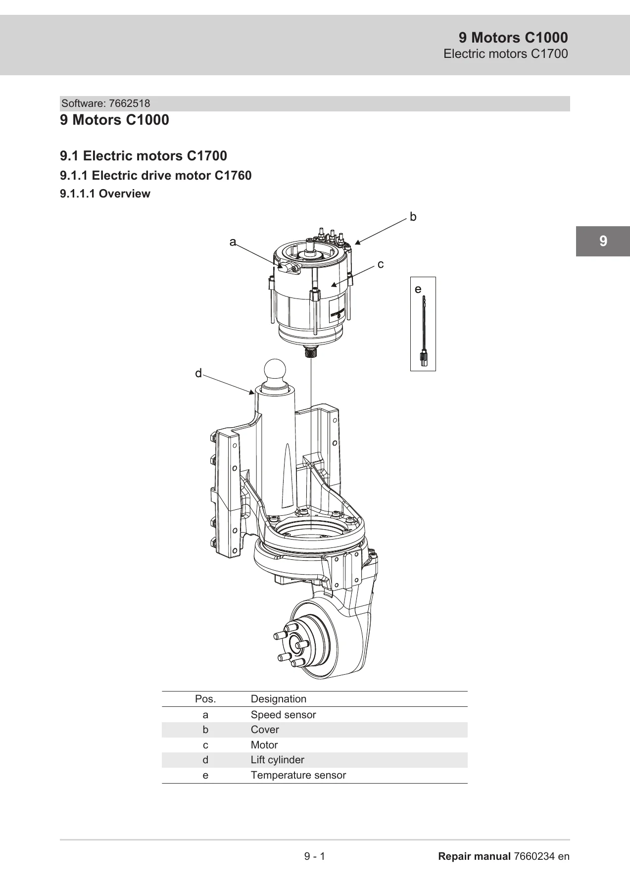
- 9 Motors C1000 – electric drive motor, cleaning and inspection, tightening of mountings, replacement, temperature sensor, rotational speed sensor, bearings, toothed wheel, tightening torques
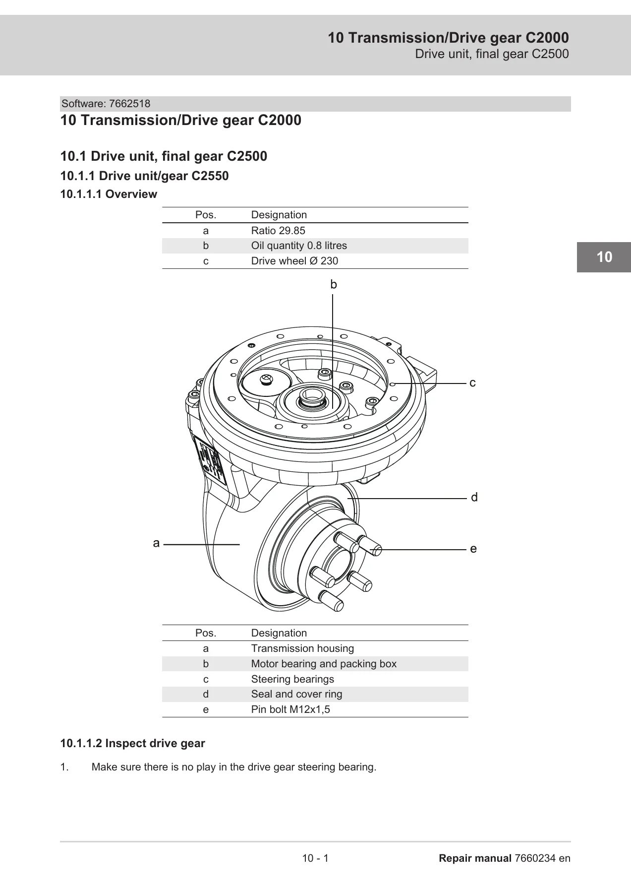
- 10 Transmission/Drive gear C2000 – drive unit overview, drive gear inspection, oil change, drive gear replacement, wheel hub seal, stud replacement, grease nipples and steering bearing lubrication
- 11 Brake/wheel/track system C3000 – brake types, electrically controlled service brake, travel brake function checks, parking brake cleaning, gap adjustment, emergency release and replacement, drive wheel, castor wheels, fork wheels, side guide wheels
- 12 Steering system C4000 – operating panel, safety reversing switch, sensilift, keypad, logic card, tiller arm handle, tiller arm, gas strut, tiller arm cover and housing
- 13 Electrical system C5000 – anti-static handling, TruckCom connection and software update, lithium-ion TMHMS battery system, BMS, battery replacement and modules, PMU, built-in battery charger, main contactor, instrument panel menus, hour counter, drive motor cables and fuses, motor control panel, wiring harnesses, I_Site, OCC, height and LSwLF sensors, emergency switch off
- 14 Hydraulics/Pneumatics C6000 – hydraulic hygiene rules, quick change connectors, hydraulic unit, oil tank level and oil change, air filter, pressure limiting valve adjustment, hydraulic unit replacement, main lift cylinders, tightening torques
- 15 Work function – lifting mast C7000
- 16 Auxiliary equipment, installation equipment C8000
- 17 Optional equipment/Extra equipment C9000 – low speed with low forks, fire extinguisher, Spider expansion unit
- 18 Instructions for disposal – recycling and transport, marking of plastics, pressure vessels and gas struts, sorting categories
- 19 Wiring diagram – colour code table, list of fuses, component lists and detailed diagrams
- 20 Hydraulic diagrams – symbol list, component list, flow diagram
- 21 Tools – tools for electric connectors, lubricating tools, special tools
- 22 Service data and grease specifications – general tightening torques, lubricants specification
- 23 Technical data – truck dimensions and truck data
- 24 Index
What makes this Cesab LWI160 repair manual useful is the way it moves from theory to bench work. The opening chapters explain how the truck behaves and how the control system is configured, which means the parameter and operating-principle sections can be read alongside the fault-finding chapter rather than in isolation. From there the manual switches to the C-code chapters, where each major assembly is broken down into removal, inspection, installation and torque figures. The troubleshooting chapter alone carries dozens of numbered error codes – from CAN communication and Hall sensor faults through to pump motor voltage, lowering valve and shock sensor messages – each with the likely cause and the recommended action. The manual closes with the wiring and hydraulic diagrams plus a full technical data table for the LWI160.
Systems and Components Documented
- Drive motor with temperature sensor, RPM sensor, bearings and toothed wheel
- Drive gear and transmission housing, oil quantity and ratio data
- Electromagnetic parking brake, service brake and safety reversing switch
- Drive wheel, castor wheels, fork wheels and side guide wheels
- Steering arm, tiller arm, gas strut, keypad and tiller arm logic card
- Motor control panel, main contactor, fuses and motor wiring harnesses
- Lithium-ion battery system, battery modules, PMU, BMS and built-in charger
- Hydraulic unit, pump motor, lowering valve, pressure limiting valve and lift cylinder
- Position and protective sensors including OCC steering angle, height sensor and LSwLF
- Spider expansion unit for customised functions
Diagnostics, Parameters and Error Codes
The troubleshooting chapter lists error codes grouped by system – ICH and CAN faults, motor control faults, hydraulic and pump motor faults, charger and BMS faults – and pairs each code with the truck behaviour you will observe, the error cause, and the step-by-step action to take. Alongside this, the parameters chapter documents the operator, service, factory and calibration parameter ranges so a technician can set travel speed, acceleration, Turtle mode limits, fork lowering speed and optional function assignments through TruckCom or the truck keypad.
What This Manual Enables You to Do
With this Toyota LWI160 repair manual open on the bench you can diagnose a fault from the error code list, strip and rebuild the drive motor, replace the parking brake, service the drive gear and refill it to the correct oil quantity, adjust the pressure limiting valve, replace the hydraulic unit, work through the battery modules and PMU, and check every circuit against the wiring diagram rather than guessing at a connector. Torque values appear where they matter – brake retaining screws, motor mountings, drive wheel nuts, terminal pillars, copper bars – so fasteners go back to specification instead of feel.
That level of detail matters on a low-lifter because the same symptom can come from the motor control, the CAN bus, the battery management system or a sensor, and swapping parts until something works is expensive. Having the correct procedure and the correct specification in front of you is what keeps the truck safe, keeps the repair first-time, and keeps the machine out of the workshop.
IMAGES PREVIEW
The manual is delivered as an instant PDF download after payment. There is no shipping and no waiting. Open it on a laptop, tablet or phone in the workshop, print the pages you need for the job in front of you, and keep the diagrams to hand while you work.

Reviews
There are no reviews yet.