★ TRUSTED BY 321,897+ PROFESSIONALS WORLDWIDE
🏒
Trusted Business
Verified & Licensed
πŸ›‘οΈ
Virus Free Files
100% Safe Downloads
πŸ”’
Secure Payment
SSL Protected
⚑
Instant Delivery
Available Immediately
Sale!

Cessna 150 F150 Parts Catalog 1963-1969 Illustrated PDF Download

Original price was: $34.95.Current price is: $21.95.

Complete illustrated Cessna 150 and French-built F150 parts catalog covering 1963-1969 models, serial 17001 through 15071128 and F150-0001 through F150-0529. Exploded views, part numbers, hardware codes, and serial-based usage tables in one PDF.

⚑
Instant PDF Download
Available immediately
πŸ’Ύ
Save to Your Device
Download & keep forever
πŸ›‘οΈ
Antivirus Scanned
100% virus-free
🌍
Trusted Worldwide
175,000+ customers

Description

Cessna 150 F150 Parts Catalog 1963-1969 – Illustrated PDF

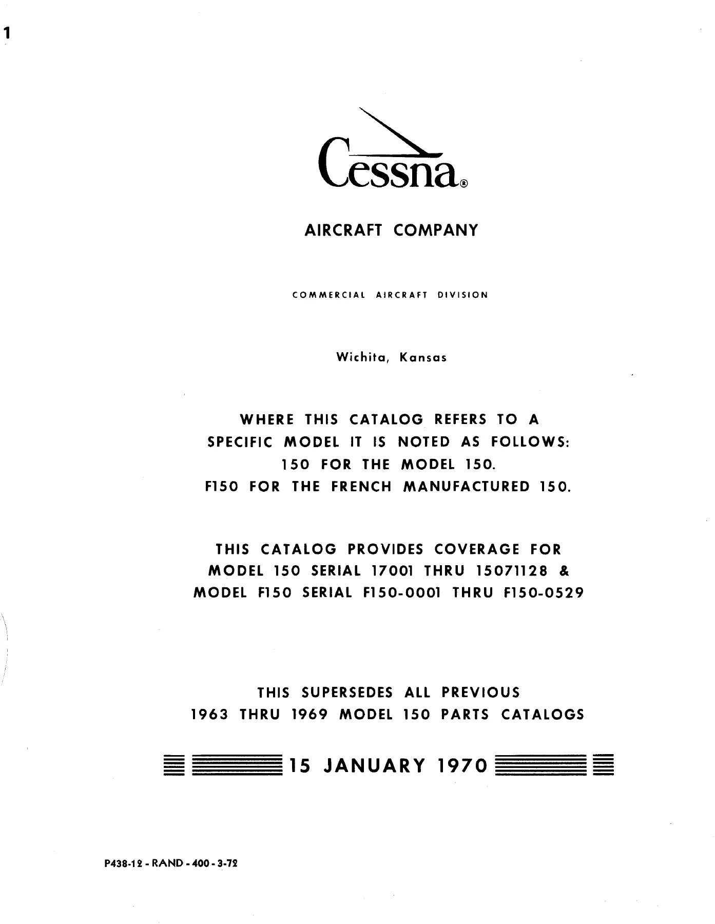
This is the consolidated Cessna parts catalog for the Model 150 and the French-manufactured F150, dated 15 January 1970 and issued to supersede all previous 1963 through 1969 Model 150 parts catalogs. It is a parts identification and ordering reference built around exploded illustrations, index numbers, part numbers, and serial-based usable-on codes.

File Details

  • Manual type: Illustrated parts catalog
  • Brand: Cessna Aircraft Company, Commercial Aircraft Division, Wichita, Kansas
  • Models covered: 150 and F150 (French-manufactured 150)
  • Coverage years: 1963 through 1969 models
  • Serial coverage: 150 – 17001 thru 15071128; F150 – F150-0001 thru F150-0529
  • Publication date: 15 January 1970
  • Language: English
  • File format: PDF

Chapters and Assemblies Covered

The catalog is organized by figure number, with each figure carrying its own parts list. Coverage spans the airframe, systems, powerplant, and furnishings of the 150 and F150:

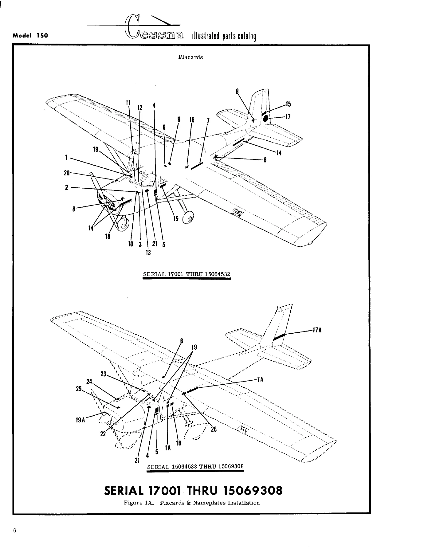
  • Placards, Nameplates & Exterior Markings – operational limitations, finish & trim plate, baggage placards, insignia
  • Wing Assembly – complete wing, patroller wing, wing structure, leading edge, strut installation
  • Fuel Tanks – wing fuel tank installation, patroller wing tanks, drain valve
  • Aileron and Flap Installations – aileron, flap, flap control system, electric flap system
  • Empennage – stabilizer and elevator, vertical fin, rudder, dorsal, fin installation
  • Fuselage – front and center section, doorpost bulkhead, tailcone, aft tailcone, message drop tube
  • Alighting Gear – nose gear, heavy-duty nose gear, main landing gear, shimmy dampener
  • Wheels and Brakes – 5.00 x 5, 6.00 x 6, heavy-duty nose wheel, master brake cylinder
  • Seating and Upholstery – standard seat, child seat, reclining seat, auxiliary seat, cabin top, side panels, floorboard
  • Doors and Windows – left and right cabin doors, patroller door, cabin door latch
  • Instruments – panel equipment, switch panel, gyro and static systems
  • Map Compartment – glove box, map case and door
  • Fuselage Equipment – shoulder harness, sun visor, fire extinguisher, compass, tow hook, mirror
  • Propeller and Spinner – metal propeller and spinner installations
  • Winterization – engine winterization equipment
  • Cowling – engine cowl assembly, upper and lower cowl
  • Engine – engine installation, engine assembly, exhaust stacks, baffles
  • Heating and Ventilating – cabin heating and ventilating system
  • Flight Controls – brake and rudder pedals, control tee, control Y, rudder, aileron, elevator, elevator trim
  • Pitot and Stall Warning Systems
  • Brake System, Fuel System, Oil System, Vacuum System
  • Electrical Equipment – battery, contactor, alternator, instrument panel lights, landing light, beacons, courtesy light, control wheel map light
  • Floatplane Fittings and Oil Cooler – floatplane-only installations

Complete PDF Bookmark Tree

Complete Bookmarks

The complete bookmarks in the β€œCessna 150 F150 Parts Catalog 1963-1969 Illustrated PDF Download” are as follows:

Coverp. 1
List of Effective Pagesp. 2
Revision – 10/15/70p. 3
Introductionp. 5
Upholstery & Interior Trimp. 17
Alphabetical Indexp. 25
A – Bp. 26
Cp. 28
Dp. 30
Ep. 31
Fp. 32
G – Hp. 34
Ip. 35
J – Lp. 36
Mp. 37
N – Pp. 38
Rp. 39
Sp. 40
Tp. 43
U – Vp. 44
Wp. 45
Parts Listing / Figuresp. 47
Fig 1. Miscellaneous Bulk Itemsp. 50
Fig 1A. Placards & Nameplates Installationp. 52
Fig 1B. (Sheet 1 of 3) Placards, Nameplates & Exterior Markingsp. 56
Fig 1B. (Sheet 2 of 3) Placards, Nameplates & Exterior Markingsp. 57
Fig 1B. (Sheet 3 of 3) Placards, Nameplates & Exterior Markingsp. 58
Fig 1C. Wing Assembly Completep. 60
Fig 1D. Patroller Wing Assembly Completep. 64
Fig 2. Wing Structure Assemblyp. 68
Fig 2A. Patroller Wing Structure Assemblyp. 72
Fig 3. Wing Leading Edge Assemblyp. 78
Fig 4. Fuel Tank Installationp. 80
Fig 4A. Patroller Wing Fuel Tank Installationp. 82
Fig 4B. Fuel Tank Drain Valve Installationp. 84
Fig 5. Aileron Installationp. 86
Fig 6. Flap Installationp. 88
Fig 7. Wing Strut Assemblyp. 91
Fig 7A. Wing Strut Assemblyp. 92
Fig 8. Stabilizer and Elevator Installationp. 96
Fig 9. Vertical Fin, Rudder and Dorsal Installationp. 100
Fig 9A. Fin Installationp. 104
Fig 9B. Rudder Installationp. 106
Fig 10. Fuselage Assemblyp. 108
Fig 10A. Fuselage Assemblyp. 110
Fig 10B. Fuselage Assemblyp. 112
Fig 11. Fuselage Front and Center Section Assemblyp. 114
Fig 11A. Front & Center Section – Fuselagep. 118
Fig 11B. Landing Gear Bulkhead Assemblyp. 122
Fig 12. Fuselage Front Section Assemblyp. 124
Fig 12A. Fuselage Front Section Assemblyp. 128
Fig 12B. Fuselage Front Section Assemblyp. 130
Fig 12C. Fuselage Front Section Assemblyp. 134
Fig 13. Front Doorpost Bulkhead Assemblyp. 138
Fig 13A. Front Doorpost Bulkhead Assemblyp. 140
Fig 14. Fuselage Tailcone Assemblyp. 142
Fig 14A. Fuselage Tailcone Assemblyp. 146
Fig 14B. Fuselage Tailcone Assemblyp. 148
Fig 14C. Aft Tailcone Assemblyp. 152
Fig 15. Windshield Installationp. 155
Fig 15A. Message Drop Tube Installationp. 156
Fig 16. Nose Gear Installationp. 158
Fig 16A. Nose Gear Installationp. 160
Fig 16B. Nose Gear Installation – Heavy Dutyp. 162
Fig 17. Nose Gear Strut Assemblyp. 164
Fig 17A. Nose Gear Strut Assemblyp. 168
Fig 17B. Heavy Duty Nose Gear Strut Assemblyp. 170
Fig 18. Main Landing Gear Installationp. 174
Fig 18A. Main Landing Gear Installationp. 176
Fig 18B. Main Landing Gear Installationp. 180
Fig 19. Seat Installationp. 182
Fig 19A. Child Seat Installationp. 184
Fig 19B. Reclining Seat Installationp. 186
Fig 19C. Auxiliary Seat Installationp. 190
Fig 19D. Auxiliary Seat Installationp. 192
Fig 20. Upholstery Installationp. 196
Fig 20A. Upholstery Installationp. 200
Fig 20B. Upholstery Installationp. 202
Fig 20C. Cabin Top and Firewall Upholstery Installationp. 206
Fig 20D. Cabin Side Panels & Floorboard Upholstery Installationp. 208
Fig 21. Left Cabin Door Assemblyp. 210
Fig 22. Right Cabin Door Assemblyp. 214
Fig 22A. Patroller Door Assemblyp. 218
Fig 22B. Cabin Door Installationp. 222
Fig 22C. Cabin Door Installationp. 226
Fig 22D. Cabin Door Latch Assemblyp. 230
Fig 23. Instrument Panel Equipment Installationp. 232
Fig 23A. Instrument Panel Equipment Installationp. 236
Fig 23B. Instrument Panel Equipment Installationp. 242
Fig 23C. Instrument Panel Equipment Installationp. 246
Fig 23D. Instrument Panel Equipment Installationp. 250
Fig 23E. Instrument Panel Equipment Installationp. 254
Fig 23F. Switch Panel Assemblyp. 258
Fig 24. Glove Box Installationp. 261
Fig 24A. Map Case and Door Installationp. 262
Fig 24B. Glove Box Installationp. 264
Fig 24C. Glove Box Installationp. 266
Fig 25. Fuselage Equipment Installationp. 268
Fig 25A. Fuselage Equipment Installationp. 272
Fig 25B. Compass Installationp. 274
Fig 25C. Compass & Sun Visor Installationp. 276
Fig 26. Propeller and Spinner Installationp. 278
Fig 27. Engine Winterization Installationp. 281
Fig 27A. Winterization Equipment Installationp. 282
Fig 28. Engine Cowl Assemblyp. 284
Fig 28A. Engine Cowl Assemblyp. 286
Fig 29. Engine Installationp. 288
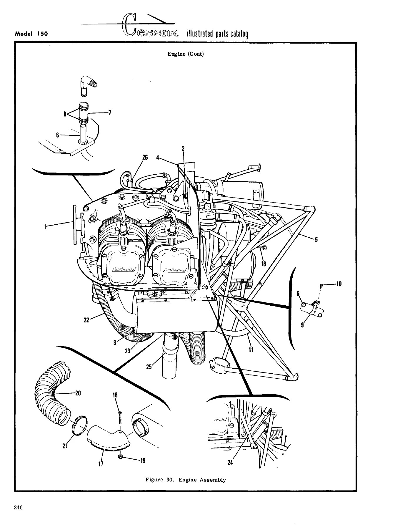
Fig 30. Engine Assemblyp. 292
Fig 31. Engine Exhaust Stacks Assemblyp. 296
Fig 32. Engine Baffles Installationp. 298
Fig 33. Cabin Heating and Ventilating System Installationp. 302
Fig 33A. Cabin Heating and Ventilating System Installationp. 304
Fig 33B. Cabin Heating & Ventilating System Installationp. 308
Fig 34. Brake and Rudder Pedal Installationp. 312
Fig 35. Control Tee Installationp. 314
Fig 35A. Control Y Installationp. 316
Fig 35B. Control Y Installationp. 320
Fig 36. Rudder Control System Installationp. 322
Fig 36A. Rudder Control System Installationp. 324
Fig 37. Aileron Control System Installationp. 326
Fig 37A. Aileron Control System Installationp. 330
Fig 37B. Wing Leveler Installationp. 332
Fig 37C. Wing Leveler Componentsp. 334
Fig 38. Flap Control System Installationp. 340
Fig 38A. Flap Control System Installationp. 344
Fig 38B. Electric Flap System Installationp. 346
Fig 38C. Flap Position Indicator Installationp. 350
Fig 39. Elevator Control System Installationp. 352
Fig 40. Elevator Trim Control System Installationp. 354
Fig 40A. Elevator Trim Control System Installationp. 356
Fig 40B. Elevator Trim Control System Installationp. 358
Fig 41. Pitot System Installationp. 360
Fig 41A. Stall Warning Horn Installationp. 364
Fig 42. Brake System Installationp. 366
Fig 42A. Brake System Installationp. 368
Fig 43. Fuel System Installationp. 372
Fig 43A. Fuel System Installationp. 376
Fig 43B. Fuel Strainer Assemblyp. 379
Fig 44. Oil System Installationp. 380
Fig 45. Vacuum System Installationp. 384
Fig 45A. Vacuum System Installationp. 388
Fig 45B. Vacuum System Installationp. 390
Fig 45C. Useage Table For C661002-0201 & C661001-0201 Gyrosp. 393
Fig 45D. Vacuum System Installationp. 394
Fig 45E. Vacuum System Installationp. 398
Fig 46. Electrical Equipment Installationp. 400
Fig 46A. Electrical Equipment Installationp. 404
Fig 46B. Instrument Panel Lights Installationp. 408
Fig 46C. 60 Amp Alternator Installationp. 410
Fig 47. Landing Light Installationp. 411
Fig 48. Rotating Beacon Installationp. 412
Fig 48A. Flashing Beacon Light Installationp. 414
Fig 49. Courtesy Light Installationp. 417
Fig 50. Control Wheel Maplight Installationp. 418
Fig 51. Main Landing Gear Wheel and Brake Assemblyp. 419
Fig 51A. Main Landing Gear Wheel and Brake Assemblyp. 420
Fig 51B. Main Landing Gear Wheel & Brake Assembly 6.00×6p. 422
Fig 51C. Main Wheel & Brake Assemblyp. 424
Fig 52. Nose Gear Wheel Assemblyp. 426
Fig 52A. Nose Gear Wheel Assemblyp. 428
Fig 52B. Nose Gear Wheel Assembly – Heavy Dutyp. 430
Fig 53. Shimmy Dampener Assemblyp. 432
Fig 53A. Shimmy Dampener Assemblyp. 434
Fig 54. Master Brake Cylinder Assemblyp. 436
Fig 54A. Master Brake Cylinder Assemblyp. 438
Fig 55. Floatplane Fittings Installationp. 440
Fig 56. Oil Cooler Installation – Floatplanep. 444
Numerical Indexp. 447

Across all of these figures, the catalog provides the identifying part number for every replaceable item, the quantity used per assembly, and the usable-on code that ties each part to specific aircraft serials. The introductory pages explain the standard parts system (S- prefix, AN and NAS hardware), the letter-code serial listings, non-interchangeable vs. interchangeable parts with “when exhausted use” notes, and the symbols used in the units-per-assembly column including NP (not procurable) and AR (as required). A full alphabetical index at the front and a numerical index at the back let you cross-reference a part number to every figure in which it appears.

What This Parts Catalog Gives You

Because the 150 and F150 changed across the 1963-1969 production run, the same nominal part can differ by serial block. This catalog handles that with letter-coded usable-on listings placed directly beneath each figure’s parts table, so you can match a part to the exact serial range of the aircraft in front of you instead of ordering by guesswork. The exploded illustrations show how components stack together – attaching hardware, brackets, seals, doublers, bearings, and fittings – which is exactly what you need when reassembling a wing, a door, a landing gear leg, or an instrument panel after inspection or repair.

The Cessna 150 F150 Parts Catalog 1963-1969 Illustrated PDF also documents the French-built F150 serials alongside the U.S. serials on the figures where the two differ, and it flags floatplane-only and patroller-only variants so you are not caught ordering a standard part for a float-equipped or patroller airframe. Placard, nameplate, and exterior marking figures list the operational limitations placards, baggage load limits, and identification markings by serial, which is useful when restoring correct factory markings.

Why a Dedicated Parts Catalog Matters

Working from an incorrect part number on a light aircraft can mean a bracket that does not line up, a seal that does not seat, or a control component that is not approved for that serial block. This catalog solves that by giving you the exact part number, the quantity, and the serial applicability in one place, with the illustration right next to the list. For owners maintaining a classic 150 or F150, for shops that service them, and for restorers chasing correct hardware, it replaces guesswork with the numbers Cessna published.

IMAGES PREVIEW

Cessna 150 F150 Parts Catalog 1963-1969 Illustrated PDF Download β€” PDF page 1 preview
Cessna 150 F150 Parts Catalog 1963-1969 Illustrated PDF Download β€” PDF page 52 preview
Cessna 150 F150 Parts Catalog 1963-1969 Illustrated PDF Download β€” PDF page 292 preview

The file is delivered as an instant PDF download – no shipping, no waiting on a physical book. It opens on any device, and any page or figure can be printed and taken to the bench or the hangar. If you are ordering parts, planning a repair, or documenting a restoration, having the illustrated parts catalog on hand means you can confirm the number before you buy.
Reviews

There are no reviews yet.

Be the first to review “Cessna 150 F150 Parts Catalog 1963-1969 Illustrated PDF Download”

What Our Customers Say

β˜…β˜…β˜…β˜…β˜… Live reviews from customers
Loading customer reviews...
0
    0
    Your Cart
    Your cart is emptyReturn to Shop
    πŸ›’
    Recently Purchased
    πŸ•’ verified order