
Cessna 206 & T206 Series 1974-1986 Illustrated Parts Catalog U206F U206G Stationair
Original price was: $32.95.$19.95Current price is: $19.95.
Cessna 206 & T206 Series illustrated parts catalog covering 1974-1986 Stationair and Turbo Stationair U206F and U206G airplanes, with exploded views, part numbers, and usable-on serial codes.
Description
Cessna 206 & T206 Series 1974-1986 Illustrated Parts Catalog U206F U206G Stationair
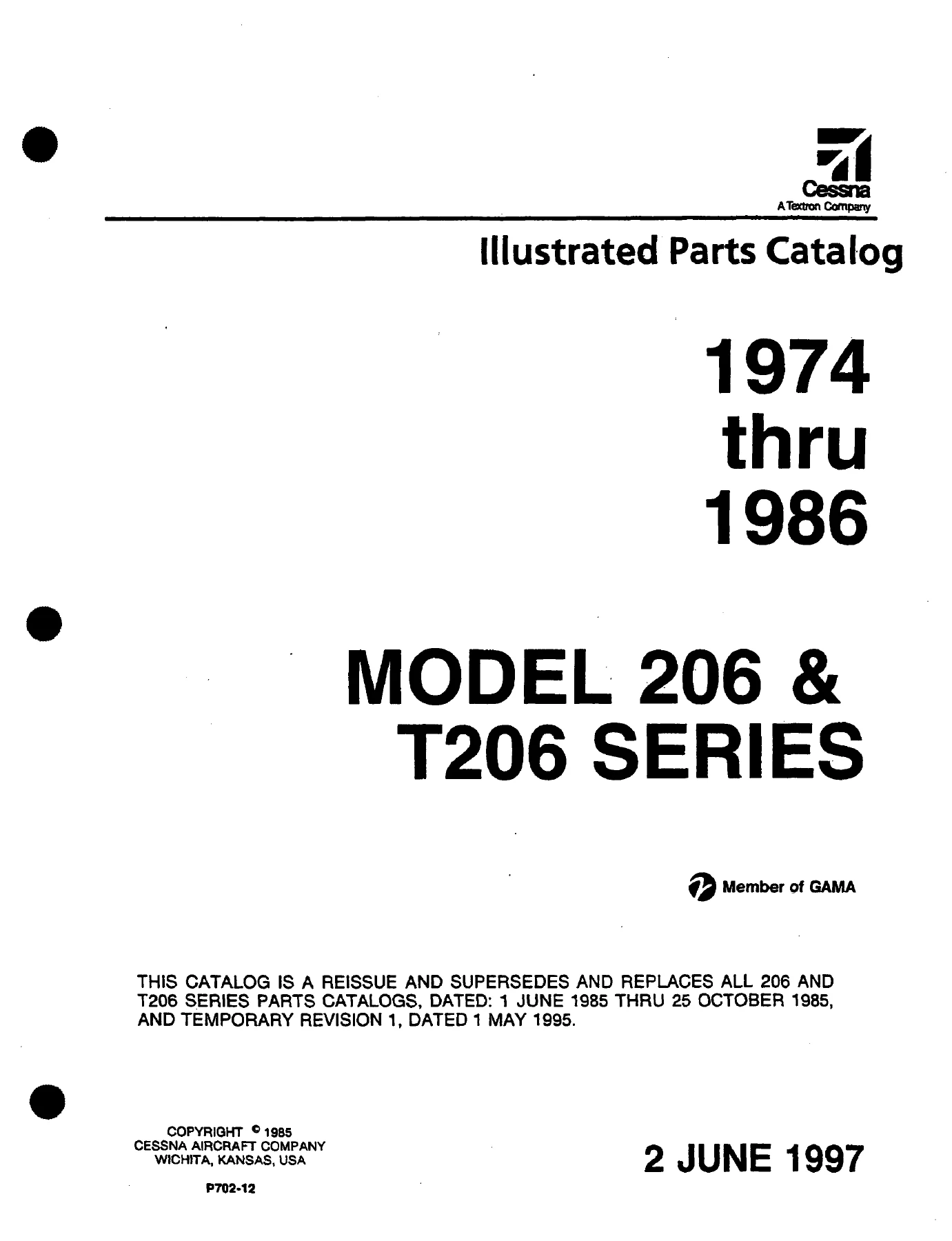
This Cessna 206 & T206 Series 1974-1986 Illustrated Parts Catalog U206F U206G Stationair is the 2 June 1997 reissue of the Cessna Aircraft Company parts catalog for the 206 and T206 series built from 1974 through 1986. Publication number P702-12 supersedes the 206 and T206 series parts catalogs dated 1 June 1985 through 25 October 1985 and Temporary Revision 1 dated 1 May 1995. It is written so a mechanic, owner, or parts buyer can match a Cessna part number to the correct figure, quantity, and serial block instead of guessing from a later or earlier 206.
File Details
- Manual type: Illustrated Parts Catalog
- Brand / models: Cessna Aircraft Company — 206 & T206 Series (U206F, U206G, TU206 Stationair and Turbo Stationair)
- Coverage years: 1974 thru 1986
- Language: English
- Publication number / date: P702-12, 2 June 1997 reissue (copyright 1985 Cessna Aircraft Company, Wichita, Kansas)
- Page count: 696 pages in the Cessna publication (List of Effective Pages); this PDF file is 729 pages including the ATP grid index wrapper
- File format: PDF
Airplanes and Serial Blocks Covered
The catalog uses certificated model numbers throughout and supplies a popular-name cross reference. Normally aspirated airplanes appear as Stationair, Stationair II, Stationair 6, and Stationair 6 II. Turbocharged airplanes appear as Turbo Stationair, Turbo Stationair II, Turbo Stationair 6, and Turbo Stationair 6 II. Model years and serials printed in that table are:
- 1974 U206F — U20602200 thru U20602579
- 1975 U206F — U20602580 thru U20603020
- 1976 U206F — U20603021 thru U20603521
- 1977 U206G — U20603522 thru U20604074
- 1978 U206G — U20604075 thru U20604649
- 1979 U206G — U20604650 thru U20605309
- 1980 U206G — U20605310 thru U20605919
- 1981 U206G — U20605920 thru U20606439
- 1982 U206G — U20606440 thru U20606699
- 1983 U206G — U20606700 thru U20606788
- 1984 U206G — U20606789 thru U20606846
- 1985 U206G — U20606847 thru U20606920
- 1986 U206G — U20606921 and on
Individual figure notes often carry usable-on letters that run as far as U20607020 and split U206 versus TU206 installations. Reims Aviation serial usage is listed with Cessna serial usage on figures where it applies. Standard-range and extended-range wing assemblies are broken out separately, as are 12-volt and 24-volt firewall and stall-warning arrangements.
Chapters Covered
- General information — title page, manufacturer’s introduction, standard parts, symbols and part-number terms, group assembly parts list arrangement, accessory kits, bulk items, how to order, serial / color / corrosion proofing, distributor and retail orders, additional publications
- Finish and trim plate explanation and yearly paint code charts (1974 through 1986)
- Record of revisions, record of temporary revisions, list of effective pages
- Upholstery and interior trim / interior painted or plastic parts by model year
- Alphabetical index and numerical index (with Aerofiche frame references)
- Miscellaneous bulk items — adhesives, sealants, hose, extrusion, electrical pins and housings
- Registration markings; nameplates, placards, and exterior markings
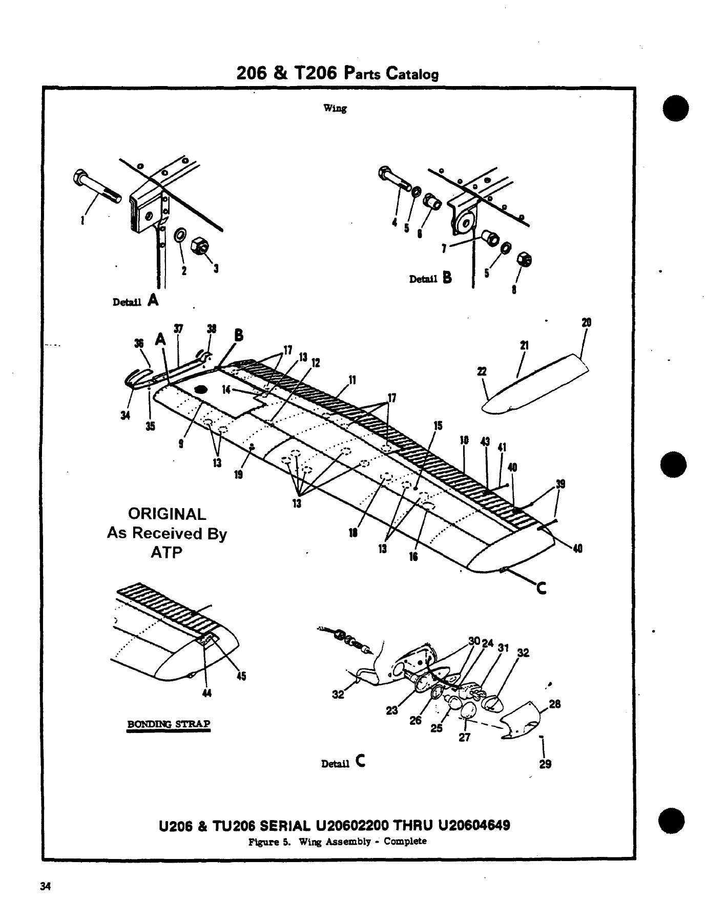
- Wing assembly complete and wing assembly complete with integral fuel cell; wing structure; skins, stringers, spars, leading edge
- Fuel cell installation, fuel tank installation, fuel tank drain valve
- Aileron, flap, and wing strut installation
- Fin and dorsal, fin and dorsal VHF comm antenna, rudder, floatplane rudder, stabilizer, elevator
- Fuselage assembly; front and center section (including openable window); forward and lower forward structure; lower removable cowl
- Firewall installation (12 volt battery and 24 volt battery); firewall grommets; pedestal; front and rear doorposts; fuselage belly; main gear actuator bulkhead
- Lower and upper aft cabin section components; cabin floorboards including club seating; cargo doors; tailcone, aft tailcone, stinger
- Windshield; nose gear, shock strut, upper structure, wheel and tire (including alternate wheel), shimmy dampener, nose gear steering
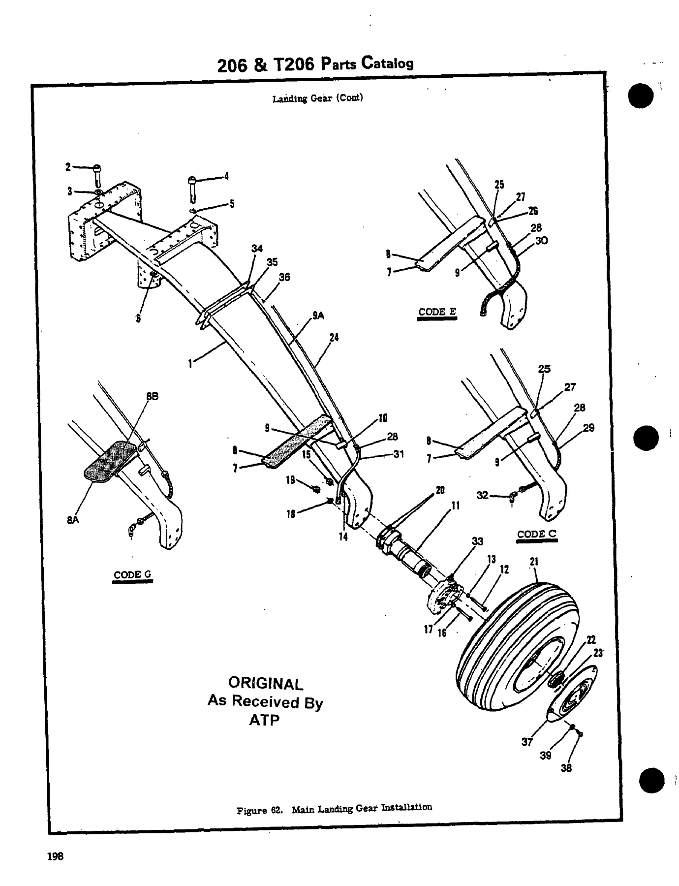
- Main landing gear; wheel fairing; wheel and brake (standard and alternate)
- Cabin door, removable latches (cargo and cabin), door and cabin-top upholstery, cargo-door and side-panel upholstery, soundproofing
- Seating — pilot and co-pilot, infinitely adjustable front seat, seat pedestal, middle and aft seats, middle aft-facing club seats, ambulance attendant seat
- Refreshment bar and table; table at seat back
- Instrument panel equipment, post lights, switch and circuit panel, brow lights, glove box, EGT seven-point gage
- Fuselage equipment, fire extinguisher, rear-view mirror and compass, seat belts and shoulder harness, inertia reel
- Step and handle; stretcher; ambulance and stretcher provisions; vertical oxygen bottle
- Two-bladed and three-bladed propeller; prop de-icer; engine cowl and nose cap
- Engine installation and engine assembly; turbocharged engine installation and assembly
- Induction airbox; turbocharger air inlet; turbocharger; exhaust valve and controller; exhaust stacks (standard and turbocharged)
- Engine baffles (standard and turbocharged); cowl flaps control; winterization equipment
- Cabin ventilation and cabin heating; windshield anti-ice detector light
- Brake system; brake and rudder pedals; brake master cylinder
- Control column; control wheel and switches
- Aileron, elevator, and rudder control systems; elevator trim, electric elevator trim, trim-tab actuator; electric flap system and flap control details; rudder trim
- Pitot system; blind encoder
- Fuel system, fuel pump and strainer, fuel strainer and drain, fuel selector valve, engine primer
- Oil system
- Vacuum system, dual-pump vacuum, standby electric vacuum; gyro installations (engine-driven, dual vacuum pump, standby electric)
- Oxygen system and oxygen console
- Electrical equipment; shock-mounted alternator; 95 amp alternator; instrument panel lights; courtesy lights; flashing beacon; ground service receptacle
- Cargo pack; floatplane and amphibian provisions; floatplane and heavy-duty fuselage structure; casket carrier, platform and rack
- Camera plane provisions, camera plane structure and floorboard; sky diving equipment
Taken together, those figures and indented group-assembly lists give a technician the replaceable hardware for the airframe, landing gear, powerplant installation, flight controls, fuel and oil plumbing, cabin interior, and the special-mission kits that were cataloged for this series. Each illustrated figure is keyed to a parts list that shows Cessna or standard (S-, AN-, NAS-) part numbers, nomenclature with indent levels, units per assembly, and a usable-on letter when the item does not apply to every serial in the book.
How the Catalog Is Organized
The introduction to the Cessna 206 & T206 Series 1974-1986 Illustrated Parts Catalog U206F U206G Stationair explains the two indexes: an alphabetical index at the front and a numerical index at the back listing every part and the figure where it appears. Frame numbers at the bottom of pages support Aerofiche use. Standard hardware is prefixed S in the Cessna standard system; AN and NAS numbers are used for common fasteners and clamps.
Usable-on codes live in the far-right column of each parts list and apply only to that figure. The letter-to-serial key is printed at the end of the figure. If no code sits next to a first-column item, the part is used on all models and serials the catalog covers. If no code sits next to an indented item, it applies to every airplane represented on that figure. Bold serial blocks are called out for quick scanning of large production runs.
When a later design is fully interchangeable, both numbers are serialized and the earlier item is marked WEU (when exhausted use) the later number. Non-interchangeable parts keep their own usable-on letters so the wrong dash number is not ordered for an early U206F or a late U206G. Attaching parts are listed immediately under the item they fasten, in the same indent column, closed by a separator before detail parts resume. Quantities for attaching hardware are per one item; multiply by the number of assemblies installed.
Bulk items such as flexible hose, moldings, channels, and windshield sealing strip are listed with the cut length used on one airplane. Accessory kits are directed to a separate accessory-kit and service-kit index rather than being expanded here. Corrosion-proofed parts are ordered by adding CO after the part number. Interior color is read from the Finish and Trim plate on the left lower door jamb, decoded with the year-specific paint code chart.
Paint, Interior, and Markings
Finish and trim plate formats change across the production run. 1974 through 1977 plates use a year digit, interior code, optional B for black carpet, and an exterior combination number, with R for arctic color reversal and SP for special paint. 1978 through 1980 plates add an overall exterior letter plus major-stripe and accent letters after a hyphen. From the 1981 model year onward the plate carries year, overall color, major stripe, and accent only. Year-by-year charts list interior materials (perforated vinyl, fabric and vinyl, leather, honeycomb nylon) against CES1054 / CES104 paint dash numbers such as Vestal White, Flag Red, Satin Blue, Pecan Brown, and Velvet Black. Nameplate and placard figures cover Stationair, Stationair II, Turbo Stationair, Stationair 6, and Stationair 6 II exterior markings, fuel-selector and filter-service placards, and related emblems.
Special Installations Called Out in the Lists
Beyond the baseline six-place Stationair airframe, the parts listing includes floatplane and amphibian structure and rudder parts, heavy-duty fuselage details, cargo-pack hardware, casket carrier platform and rack, camera-plane structure and floorboards, sky-diving equipment, ambulance attendant seating and stretcher provisions, and club-seating floorboards. Engine figures separate normally aspirated U206 installations from TU206 turbocharged stacks, baffles, induction, exhaust-valve controllers, and cowl-flap controls. Propeller figures cover two-blade and three-blade assemblies and prop de-ice. Electrical figures distinguish 12-volt and 24-volt battery firewalls and a 95 amp alternator installation. Vacuum coverage includes single-pump, dual-pump, and standby electric pump layouts.
The introduction warns that inspection intervals, replacement times, and overhaul limits in Cessna maintenance data apply only when Cessna-approved new, remanufactured, or overhauled parts are used, and that STC installations must be inspected to the STC holder’s program. Those statements sit in this parts catalog as published; this file itself is the illustrated breakdown of replaceable parts, not the service manual.
What You Can Do With This Catalog
With the Cessna 206 & T206 Series 1974-1986 Illustrated Parts Catalog U206F U206G Stationair open to the correct figure, you can identify a cracked elevator rib, a nose-gear torque-link bolt, a fuel-cell transmitter, a turbocharger exhaust-valve controller, or a cabin-door latch by index number and order the Cessna dash number that matches your serial. You can see whether a later design supersedes an earlier one (WEU), whether a wing is standard or extended range, and whether a firewall or stall-warning unit is the 12-volt or 24-volt version. Paint and interior codes from the door-jamb plate can be decoded to original CES1054 colors. Floatplane, camera, ambulance, and cargo-pack airplanes can be sourced from the same book instead of a generic 206 list that ignores those kits.
Using the serial-coded figure that actually applies to the airplane avoids mixing U206F and late U206G hardware, or fitting a normally aspirated exhaust stack to a TU206. Instant PDF delivery means the file is available on any device as soon as payment clears—no warehouse wait and no shipping. Print the exploded view and the facing parts list for the bench, or keep the full Stationair illustrated parts catalog on a tablet in the hangar.

Reviews
There are no reviews yet.