
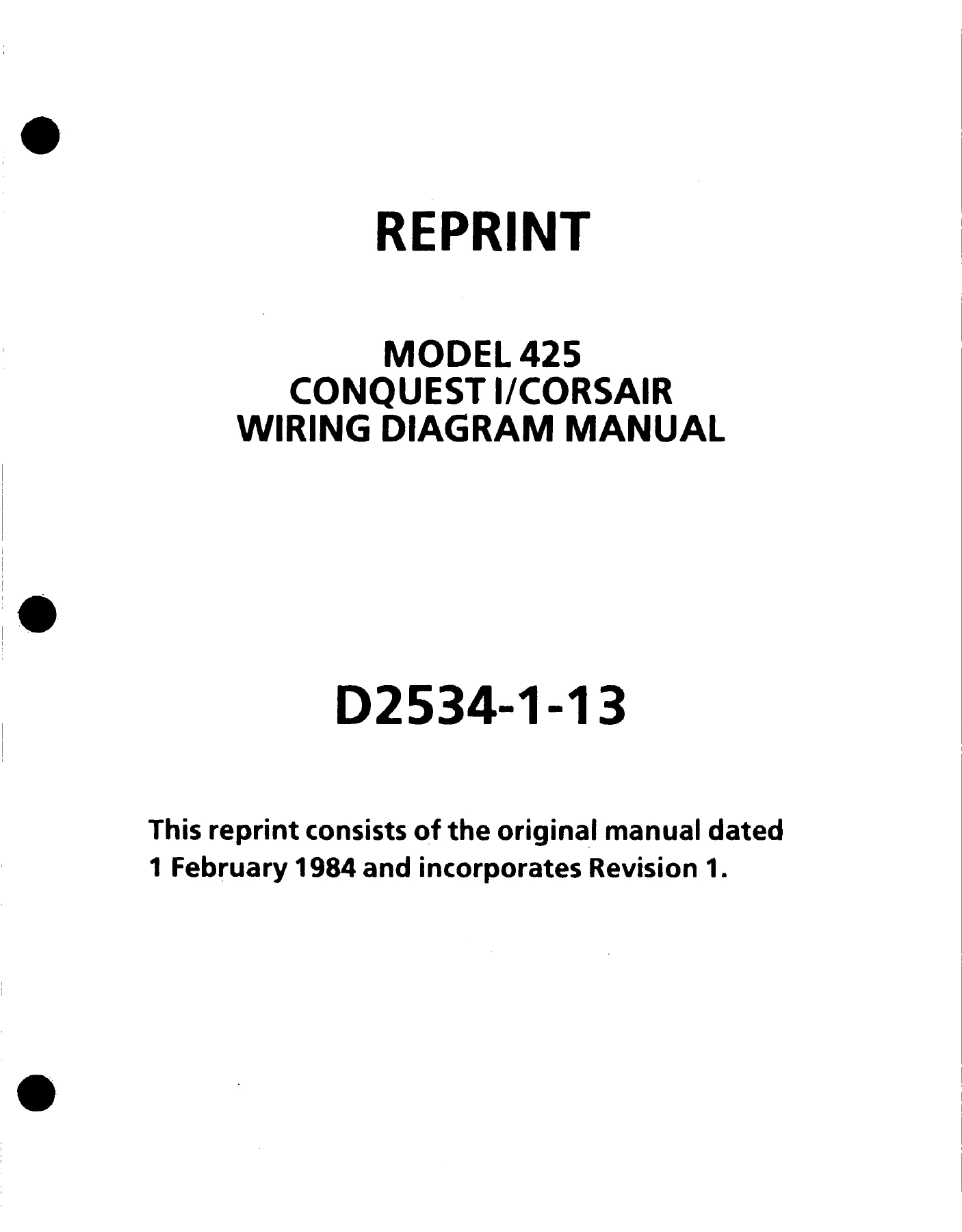
Cessna 425 Conquest I Corsair Wiring Diagram Manual 1984-1994
Original price was: $39.95.$24.95Current price is: $24.95.
Complete Cessna 425 Conquest I and Corsair wiring diagram manual covering all ATA chapters, electrical systems, avionics wiring, connectors, terminal boards, and component locations. Document D2534-1-13 with Revision 1 dated 1 December 1994.
Description
Cessna 425 Conquest I / Corsair Wiring Diagram Manual
This Cessna 425 Conquest I Corsair Wiring Diagram Manual is the complete reprint of the original manual dated 1 February 1984, incorporating Revision 1 dated 1 December 1994. Published under document number D2534-1-13, this 505-page wiring diagram manual gives maintenance personnel, avionics technicians, and operators the wiring data needed to troubleshoot, trace, repair, and maintain the electrical and avionics systems of the Model 425 Conquest I and Corsair.
File Details
- Manual Type: Wiring Diagram Manual
- Brand: Cessna Aircraft Company
- Model: 425 Conquest I / Corsair
- Document Number: D2534-1-13
- Original Manual Date: 1 February 1984
- Revision: Revision 1, 1 December 1994
- Language: English
- Page Count: 505 pages
- File Format: PDF
Chapters Covered
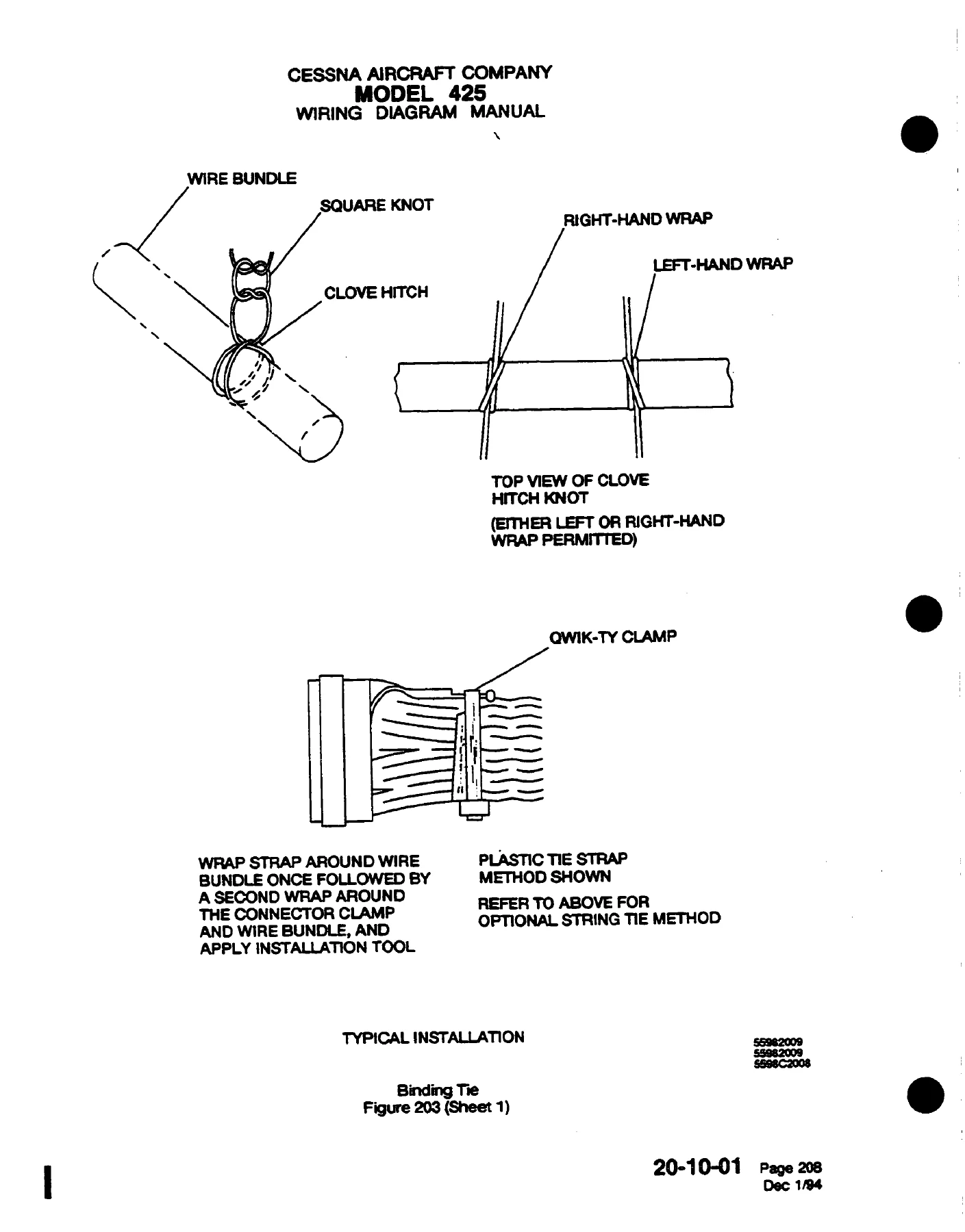
- Chapter 20 – Standard Practices (Electrical Safety, Bonding and Grounding, Connectors, Splices and Terminals, Soldering, Heat Shrink Tubing, Resistors, Torque Values, Sealing)
- Chapter 21 – Air Conditioning (Cabin Pressurization, Bleed Air, Cabin Pressure Warning CAA Airplanes, Aux Cabin Ventilation and Heat, Air Conditioning System)
- Chapter 22 – Auto Flight (General)
- Chapter 23 – Communications (Stereo 8-Track Motorola TM226S, Stereo 8-Track RCA 12R903, Stereo Cassette Sanyo FT150, Audio System, Boom Microphone Option)
- Chapter 24 – Electrical Power (Battery Overheat Monitor, Power Distribution Left Side Console, Right Power Distribution, Left Power Distribution Horizontal and Vertical Panels)
- Chapter 25 – Equipment/Furnishings (Shaver Inverter, Cabin Information Display, Refreshment Center)
- Chapter 26 – Fire Protection (LH Fire Detection and Bleed Air Overheat, RH Fire Detection and Bleed Air Overheat, Fire Extinguisher)
- Chapter 27 – Flight Controls (Stall Warning, Flap Control)
- Chapter 28 – Fuel (Fuel Pumps, Fuel Quantity and Hopper Low Fuel Warning, Low Fuel Warning, Fuel Filter By-Pass Warning)
- Chapter 29 – Hydraulic Power (Hydraulic Warning)
- Chapter 30 – Ice and Rain Protection (Surface Deice, Static Port Heater, Pitot Heat, Electric Windshield, Alcohol Windshield, Propeller Deice)
- Chapter 31 – Indicating/Recording Systems (Outside Air Temperature, Flight Hour Recorder)
- Chapter 32 – Landing Gear (Landing Gear Control, Landing Gear and Flap Warning)
- Chapter 33 – Lights (Dimmable Panel Lights, Map Lights, Electroluminescent Panels, Annunciator Light Test, Master Warning Light, Door Courtesy Light, Interior Overhead Lighting, Nose Baggage Lights, Surface Deice Lights, Taxi Light, Landing Lights, Anti-Collision and Nav Lights, Recognition Lights, Rotating Beacon Lights)
- Chapter 34 – Navigation (Angle of Attack, Turn and Bank, Gyro Inverting Switches)
- Chapter 38 – Water/Waste (Flush Toilet)
- Chapter 39 – Electrical/Electronic Panels and Multipurpose Parts (Digital Clock, Electric Clock, Diode Module, Annunciator Logic and Dimming, Annunciators)
- Chapter 52 – Doors (Door Warning)
- Chapter 61 – Propellers (Propeller Synchronizer, Propeller Synchrophaser, Propeller Autofeather, Propeller Governor, Beta Warning)
- Chapter 71 – Power Plant (Inertial Separators)
- Chapter 73 – Engine Fuel and Control (P3/PY Heaters, Fuel Flow, Fuel Totalizers)
- Chapter 77 – Engine Indicating (Tachometers, Torque Indicators, Inter Turbine Temperature)
- Chapter 79 – Oil (Engine Oil Indicating)
- Chapter 80 – Starting (Starter-Generator Control, Start Control)
Beyond the individual system diagrams, this Cessna 425 wiring diagram manual includes the reference material that makes wiring work practical: the ATA 100 wiring diagram numbering system, wire identification coding (circuit function letters, wire segment letters, wire size digits, ground/phase/thermocouple letters), thermocouple color coding, electronic wire numbering, an equipment list of electrical and avionic component designators, standard symbols used throughout the diagrams, a light bulb replacement guide, a fuse and fuse limiter replacement guide, service letter/kit lists, and manufacturer technical publication listings.
The manual’s Standard Practices chapter covers electrical safety precautions, bonding and grounding procedures, connector assembly for MS3106 series, DBA-type rear-release connectors, and other connector series, crimp and solder terminal installation, coaxial cable terminal assembly, splice installation (permanent crimp, environmental resistant, disconnect types), heat shrink tubing selection and application, resistor color coding and part number decoding, and torque values for electrical fasteners. This is the reference material you need before you start tracing circuits on the Model 425 Conquest I.
What This Wiring Diagram Manual Enables You to Do
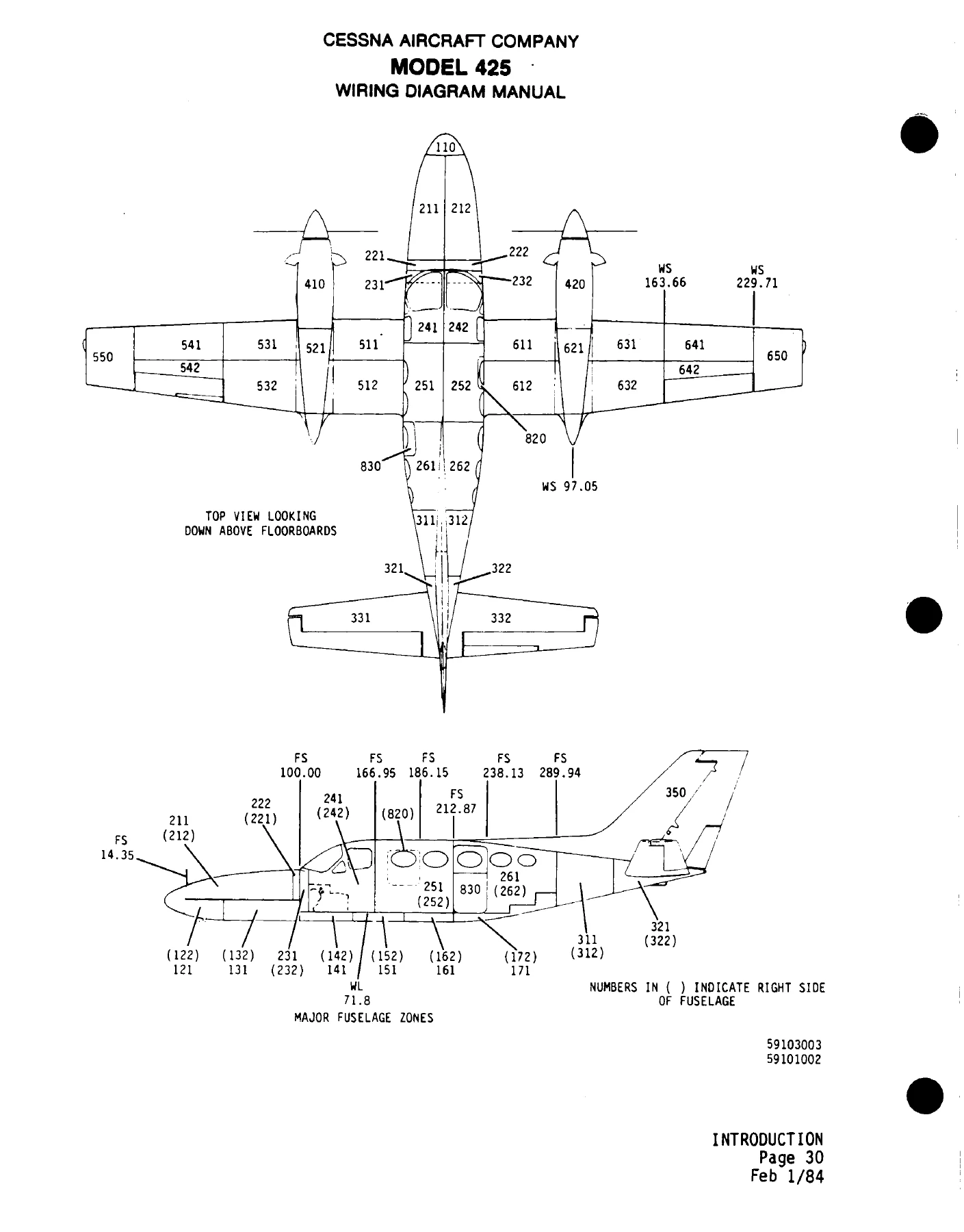
With this Cessna 425 Conquest I Corsair wiring diagram manual, you can trace circuits from power source to ground, identify wire segment routing and gage, locate connectors and terminal boards by zone, troubleshoot electrical faults systematically, remove and replace components, repair damaged wiring to the correct standard, order the right replacement parts and wiring components, and interpret every wire number, symbol, and connector pinout used on the aircraft. The manual uses the ATA 100 specification for wiring diagram numbering, so each diagram carries a chapter, subsystem, and specific diagram number – for example, 28-20-01 for the Left Fuel Distribution diagram. The zonal system divides the airplane into numbered zones (100 series for radome and nose area, 200 series for cabin, 300 series for empennage, 400 series for nacelle, 500 series for left wing, 600 series for right wing, 700 series for landing gear, 800 series for cabin and emergency doors), making component location straightforward once you identify the zone from the diagram.
Correct wiring data matters because guesswork in an aircraft electrical system is not an option. A misread connector pinout, wrong wire gage, or incorrect splice can cause intermittent faults, system failures, or worse. This manual gives you the exact wire routing, connector pin assignments, splice locations, and component reference designators so every repair and diagnosis follows the manufacturer’s wiring scheme. The equipment list translates reference designators into component types, and the wire identification system tells you the circuit function, wire segment, wire size, and whether the wire completes a ground circuit or is part of a thermocouple circuit.
IMAGES PREVIEW
Delivered as an instant PDF download, this Cessna 425 Conquest I Corsair Wiring Diagram Manual is printable and viewable on any device. No shipping, no waiting – get the wiring data for your Model 425 immediately after checkout.

Reviews
There are no reviews yet.