
CFM56-5C Basic Engine Training Manual – CFMI Turbofan PDF for Airbus A340
Original price was: $39.95.$24.95Current price is: $24.95.
CFMI training manual covering the CFM56-5C2, 5C3 and 5C4 basic engine in full – fan and booster, core engine, low pressure turbine and accessory drive modules, with bearings, seals, gearboxes and borescope inspection detail.
Description
The CFM56-5C Basic Engine Training Manual is the CFMI training publication that explains how the CFM56-5C high by-pass, dual rotor, axial flow turbofan is built and how each of its modules works. Written for the Airbus A340 installation, it covers the three thrust ratings of the engine – the CFM56-5C2 at 31,200 lbs, the CFM56-5C3 at 32,500 lbs and the CFM56-5C4 at 34,000 lbs – and works through the engine from the spinner front cone to the turbine frame flange assembly. This CFM56-5C Basic Engine Training Manual PDF is a study and reference document rather than a line maintenance task card set, and that distinction matters when you decide what you are buying.
File Details
- Manual type: Basic Engine Training Manual
- Publisher: CFMI (CFM International – GE and Snecma joint company)
- Engine covered: CFM56-5C
- Engine models covered: CFM56-5C2, CFM56-5C3, CFM56-5C4
- Aircraft application: Airbus A340
- Language: English
- Page count: 365 pages
- File format: PDF
- ATA chapter coverage: 72-00-00 through 72-63-00
Chapters Covered
- Introduction to the CFM56 Family – CFMI organisation, engine application and thrust ratings
- Engine General Concept – two-spool layout, five main bearings, two dry sump cavities
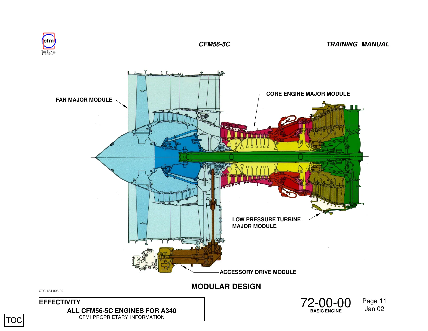
- Modular Concept – the fan, core engine, low pressure turbine and accessory drive major modules
- Fan Major Module (72-00-01)
- Fan and Booster (72-21-00) – spinner front cone, spinner rear cone, fan disk, fan blades, booster rotor, booster stator vane assembly
- No 1 and 2 Bearing Support Module (72-22-00) – No 1 bearing support, No 1 ball bearing, No 2 bearing support, No 2 roller bearing, fan shaft, air/oil separator, N1 speed sensor ring, forward stationary air/oil seal, oil manifold assembly, bearing lubrication, external piping
- Fan Frame Module (72-23-00) – fan inlet case, outlet guide vane assembly, fan frame, radial struts, mid-box structure, centre hub, radial drive shaft housing
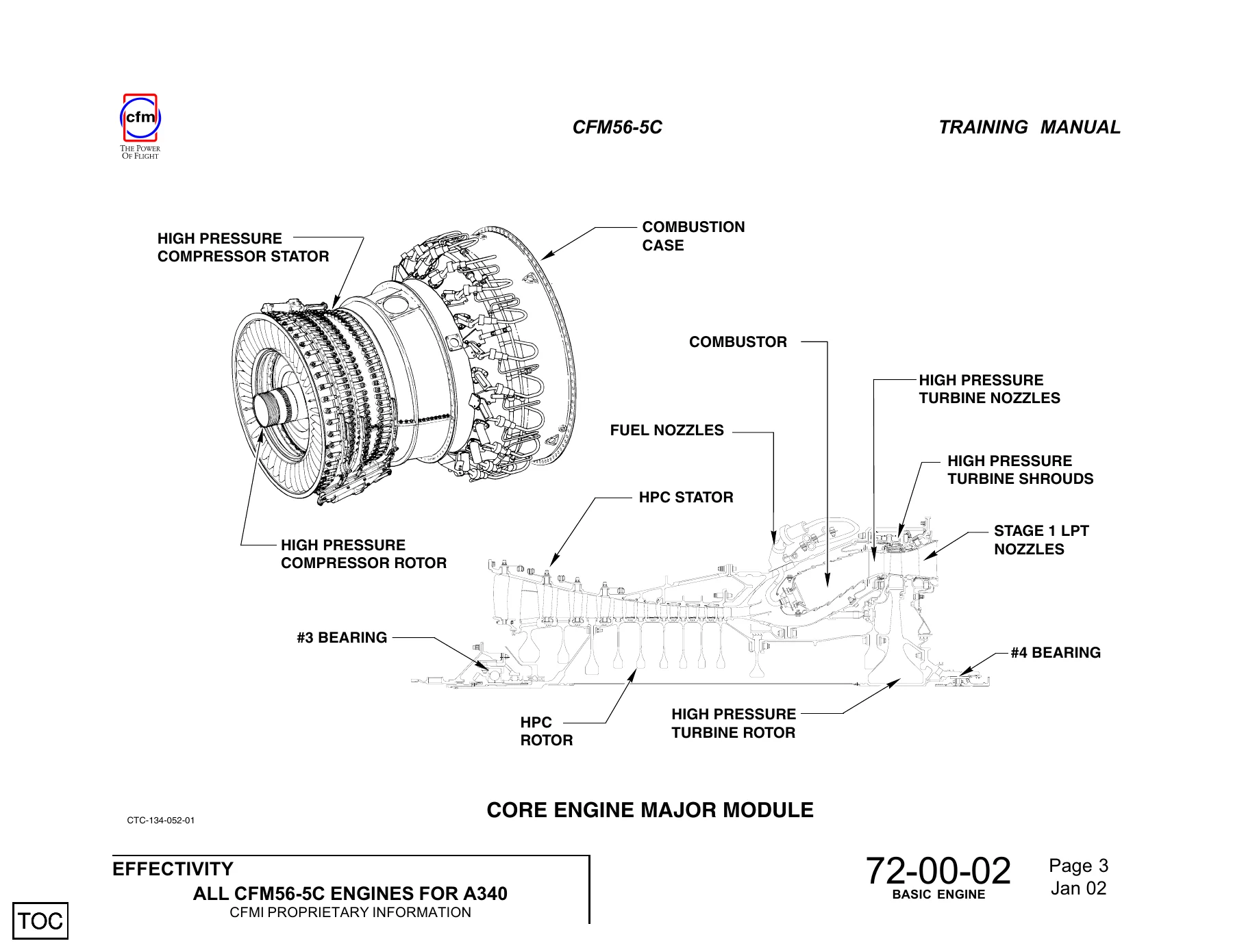
- Core Engine Major Module (72-00-02)
- Compressor Rotor (72-31-00) – rotor shaft, stage 1-2 spool, stage 3 disk, stage 4-9 spool, rotor blade design, rear rotating (CDP) air seal
- Compressor Front Stator (72-32-00) – front stator case, variable stator vanes, fixed stator vanes, VSV actuation system
- Compressor Rear Stator (72-33-00) – rear stator case and borescope ports
- Combustion Case (72-41-00)
- Combustion Chamber (72-42-00) – swirl nozzles and dome, outer and inner cowls, outer and inner liners, borescope ports
- High Pressure Turbine (72-50-00)
- HPT Nozzle (72-51-00) – nozzle segments, forward and aft inner supports, aft outer stationary seal
- HPT Rotor (72-52-00) – front shaft, forward rotating air seal, disk, blade retainers, rotor blades, rear shaft
- HPT Shroud and Stage 1 LPT Nozzle (72-53-00) – air impingement manifold, shroud/nozzle support, shroud hangers, shrouds, stage 1 LPT nozzle
- Low Pressure Turbine Major Module (72-00-03)
- LPT Rotor/Stator Module (72-54-00) – bulkhead assembly, stator assembly, LPT case, air cooling tubes and manifolds, stages 2 to 5 nozzles, rotor assembly, disks, rotating air seals, blades, rotor support, borescope ports
- LPT Shaft Module (72-55-00) – LPT shaft, centre vent tube, No 4 bearing, No 5 bearing, bearings lubrication
- Turbine Frame Module (72-56-00) – turbine frame, hub front, hub rear
- Accessory Drive Major Module (72-60-00)
- Inlet Gearbox (72-61-00) – horizontal bevel gear, radial bevel gear, No 3 bearing, rotating air/oil seal
- Transfer Gearbox (72-62-00) – radial drive shaft, gearbox housing, input bevel gear, horizontal bevel gear
- Accessory Gearbox (72-63-00) – horizontal drive shaft, gear train, sealing arrangements
Read as a whole, this CFM56-5C Basic Engine Training Manual PDF gives a technician a complete structural and functional map of the engine. Each section names the components, explains what they do, and describes how they are assembled, mounted and sealed. The bearing arrangement that supports both rotors, the pressurisation and scavenge circuits that keep the forward and rear sumps working, the variable stator vane actuation system, the cooling air paths through the high pressure turbine and low pressure turbine – all of it is set out module by module in the order the hardware sits on the engine.
Inside the CFM56-5C Basic Engine Training Manual
The engine is presented as two independent rotating systems, the low pressure rotor designated N1 and the high pressure rotor designated N2, supported by five main bearings numbered 1 through 5 from front to back. Those bearings sit in two pressure sealed dry sump cavities provided by the fan frame and the turbine frame. The manual explains which bearings take axial loads and which take radial loads only, where each one is housed, and how oil reaches the No 1 ball bearing, the No 2 roller bearing, the No 3 thrust bearing pair in the inlet gearbox, and the No 4 and No 5 roller bearings at the rear.
The fan major module section works through the 36 titanium mid-span shrouded fan blades, the four stage booster with its blade counts for stages 2 to 5, and the booster stator vane assembly with its abradable lined shrouds. It covers the spinner front and rear cones, the offset holes and indent marks used to keep them correctly indexed, the balancing screws used for fan static and trim balance, and the fan blade root coatings.
The core engine section follows the air path: nine stage high pressure compressor, annular combustion chamber fed by 20 fuel nozzles and lit by 2 igniter plugs, single stage high pressure turbine with its 21 nozzle segments of two vanes each and 80 directionally solidified rotor blades, then the high pressure turbine shroud and stage 1 low pressure turbine nozzle. The variable stator vane system, the borescope port numbering from S1 through S21, and the HPT clearance control air manifold are all described in place.
The low pressure turbine module covers the five stage rotor and stator assembly, the bulkhead that separates the forward and aft core compartments, the LPT shaft with its centre vent tube and D48 shim, and the turbine frame with its 16 airfoil shaped struts and three clevis engine mounts. The accessory drive section closes the manual with the inlet gearbox, transfer gearbox and accessory gearbox, including the gear tooth counts, the radial and horizontal drive shafts, and the accessory drive ratios for the IDG, hydraulic pump, fuel pump, lubrication unit, alternator and starter.
Condition Monitoring and Maintenance Concept
The manual sets out the on condition maintenance concept used on the CFM56-5C – no periodic overhaul schedule, with the engine staying on the wing until something significant occurs or a part reaches its life limit. It describes the tools that support that approach: engine performance trend monitoring, borescope inspection through the ports on the outer casings, lubrication particle analysis through filters and magnetic chip detectors, spectrometric oil analysis for microscopic particles, and the engine vibration monitoring system.
Who This Manual Suits
This is a training document. It is the right purchase for anyone who needs to understand how the CFM56-5C is put together – students on a type course, engineers moving onto the A340, technical libraries, and instructors building teaching material. It is written to explain design intent and construction, not to give torque figures for a specific removal task, so it complements rather than replaces the maintenance publications. The note that the information is accurate at the time of compilation and that authorised maintenance practices and specifications should be taken from the pertinent maintenance publications is printed in the manual itself.
IMAGES PREVIEW
Instant PDF Delivery
Buying this CFM56-5C Basic Engine Training Manual gives you an immediate download – no shipping, no waiting on a courier, no physical book to keep track of. The file opens on a laptop, tablet or phone, and any page can be printed when you want a paper copy on the bench or in the classroom. If you work on or study the CFM56-5C2, CFM56-5C3 or CFM56-5C4, or you teach the engine to others, this CFM56-5C Basic Engine Training Manual PDF is the module by module grounding that makes everything else easier to follow.
Reviews
There are no reviews yet.